EP2000726A3 - Concrete shaft - Google Patents
Concrete shaft Download PDFInfo
- Publication number
- EP2000726A3 EP2000726A3 EP08010098A EP08010098A EP2000726A3 EP 2000726 A3 EP2000726 A3 EP 2000726A3 EP 08010098 A EP08010098 A EP 08010098A EP 08010098 A EP08010098 A EP 08010098A EP 2000726 A3 EP2000726 A3 EP 2000726A3
- Authority
- EP
- European Patent Office
- Prior art keywords
- edge
- shaft
- ring
- load
- manhole
- Prior art date
- Legal status (The legal status is an assumption and is not a legal conclusion. Google has not performed a legal analysis and makes no representation as to the accuracy of the status listed.)
- Withdrawn
Links
Classifications
-
- E—FIXED CONSTRUCTIONS
- E02—HYDRAULIC ENGINEERING; FOUNDATIONS; SOIL SHIFTING
- E02D—FOUNDATIONS; EXCAVATIONS; EMBANKMENTS; UNDERGROUND OR UNDERWATER STRUCTURES
- E02D29/00—Independent underground or underwater structures; Retaining walls
- E02D29/12—Manhole shafts; Other inspection or access chambers; Accessories therefor
- E02D29/14—Covers for manholes or the like; Frames for covers
- E02D29/1463—Hinged connection of cover to frame
-
- F—MECHANICAL ENGINEERING; LIGHTING; HEATING; WEAPONS; BLASTING
- F16—ENGINEERING ELEMENTS AND UNITS; GENERAL MEASURES FOR PRODUCING AND MAINTAINING EFFECTIVE FUNCTIONING OF MACHINES OR INSTALLATIONS; THERMAL INSULATION IN GENERAL
- F16L—PIPES; JOINTS OR FITTINGS FOR PIPES; SUPPORTS FOR PIPES, CABLES OR PROTECTIVE TUBING; MEANS FOR THERMAL INSULATION IN GENERAL
- F16L21/00—Joints with sleeve or socket
- F16L21/02—Joints with sleeve or socket with elastic sealing rings between pipe and sleeve or between pipe and socket, e.g. with rolling or other prefabricated profiled rings
-
- F—MECHANICAL ENGINEERING; LIGHTING; HEATING; WEAPONS; BLASTING
- F16—ENGINEERING ELEMENTS AND UNITS; GENERAL MEASURES FOR PRODUCING AND MAINTAINING EFFECTIVE FUNCTIONING OF MACHINES OR INSTALLATIONS; THERMAL INSULATION IN GENERAL
- F16L—PIPES; JOINTS OR FITTINGS FOR PIPES; SUPPORTS FOR PIPES, CABLES OR PROTECTIVE TUBING; MEANS FOR THERMAL INSULATION IN GENERAL
- F16L23/00—Flanged joints
- F16L23/02—Flanged joints the flanges being connected by members tensioned axially
- F16L23/032—Flanged joints the flanges being connected by members tensioned axially characterised by the shape or composition of the flanges
Landscapes
- Engineering & Computer Science (AREA)
- General Engineering & Computer Science (AREA)
- Environmental & Geological Engineering (AREA)
- Life Sciences & Earth Sciences (AREA)
- General Life Sciences & Earth Sciences (AREA)
- Mining & Mineral Resources (AREA)
- Paleontology (AREA)
- Civil Engineering (AREA)
- Structural Engineering (AREA)
- Mechanical Engineering (AREA)
- Ladders (AREA)
- Underground Structures, Protecting, Testing And Restoring Foundations (AREA)
Abstract
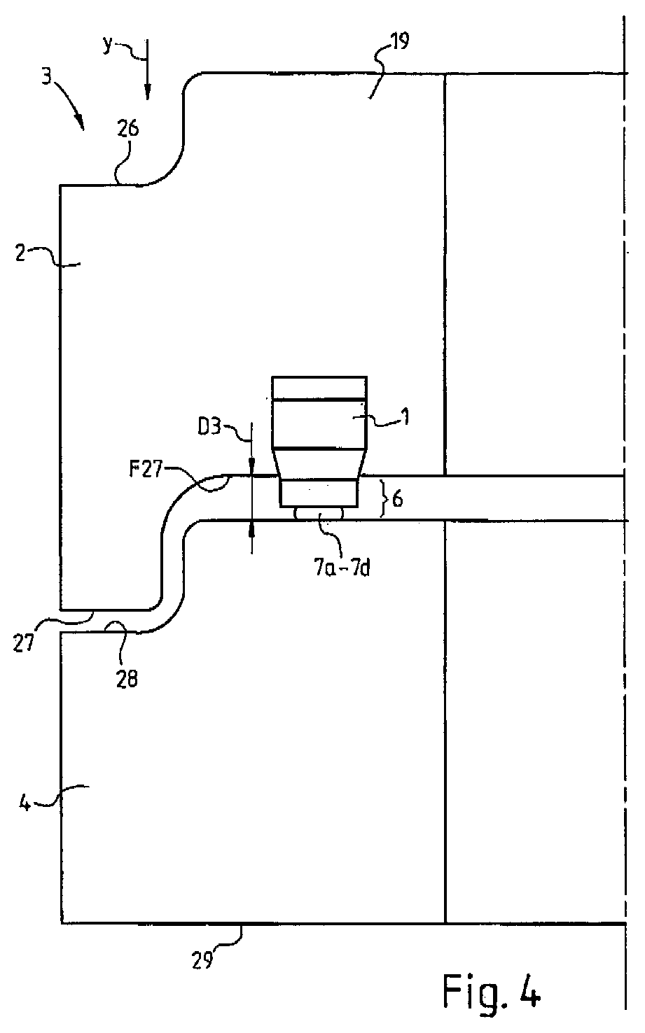
Die Erfindung betrifft einen Schacht (3) aus Beton oder dgl., wobei der Schacht (3) wenigstens einen ersten Schachtring (2) und einen zweiten Schachtring (4) umfasst, wobei die Schachtringe (2, 4) jeweils einen oberen und einen unteren Rand (26 - 29) aufweisen, wobei wenigstens der erste Schachtring (2) an seinem mit dem zweiten Schachtring (4) zusammenwirkenden unteren Rand (27) mehrere an dem Rand (27) in Abstand voneinander am Umfang verteilt angeordnete streifenförmige Lastaufnahmeelemente (1) aus Kunststoff aufweist, wobei das einzelne Lastaufnahmeelement (1) mit einem Fußteil in den Rand (27) eingebettet ist und mit einem Kopfteil über eine Stirnfläche (F27) des Randes (27) vorsteht, wobei das Fußteil an einer Fußfläche wenigstens einen Steg (8) aufweist, wobei im zusammengebauten Zustand des Schachtes (3) der zweite Schachtring (4) mit seinem oberen Rand (28) an dem Kopfteil des Lastaufnahmeelements (1) anliegt und einen Abstand (D3) zu dem unteren Rand (27) des ersten Schachtrings (2) aufweist, in welchem das Lastaufnahmeelement (8) befestigt ist.
Applications Claiming Priority (2)
| Application Number | Priority Date | Filing Date | Title |
|---|---|---|---|
| DE102007026846 | 2007-06-06 | ||
| DE102007028324.7A DE102007028324B4 (en) | 2007-06-06 | 2007-06-15 | Concrete shaft and load-bearing element |
Publications (2)
| Publication Number | Publication Date |
|---|---|
| EP2000726A2 EP2000726A2 (en) | 2008-12-10 |
| EP2000726A3 true EP2000726A3 (en) | 2008-12-31 |
Family
ID=39736962
Family Applications (1)
| Application Number | Title | Priority Date | Filing Date |
|---|---|---|---|
| EP08010098A Withdrawn EP2000726A3 (en) | 2007-06-06 | 2008-06-03 | Concrete shaft |
Country Status (1)
| Country | Link |
|---|---|
| EP (1) | EP2000726A3 (en) |
Families Citing this family (2)
| Publication number | Priority date | Publication date | Assignee | Title |
|---|---|---|---|---|
| US20130055650A1 (en) * | 2010-11-17 | 2013-03-07 | Udo Hartmann | Modular Integrated Underground Utilities Enclosure and Distribution System |
| DE102011105334B4 (en) | 2011-04-21 | 2024-11-21 | Hans Rinninger u. Sohn GmbH & Co. KG | concrete shaft and load-bearing element |
Citations (4)
| Publication number | Priority date | Publication date | Assignee | Title |
|---|---|---|---|---|
| FR1594313A (en) * | 1968-12-11 | 1970-06-01 | ||
| DE19538113A1 (en) * | 1995-10-13 | 1997-04-17 | Pt Poly Tec Gmbh | Prefabricated pin and socket concrete pipe abutment cushion |
| WO2004106798A1 (en) * | 2003-05-28 | 2004-12-09 | Trelleborg Forsheda Building Ab | Rubber strip for partial embedding into a concrete pipe, concrete pipe with partially embedded rubber strip |
| DE102004043190A1 (en) * | 2003-09-04 | 2005-03-31 | Betonrohrwerke Tröndle GmbH | Load transfer joint for vertical shaft concrete sections has hollow sealing ring with two part sealant mixed when frangible ring wall is broken |
-
2008
- 2008-06-03 EP EP08010098A patent/EP2000726A3/en not_active Withdrawn
Patent Citations (4)
| Publication number | Priority date | Publication date | Assignee | Title |
|---|---|---|---|---|
| FR1594313A (en) * | 1968-12-11 | 1970-06-01 | ||
| DE19538113A1 (en) * | 1995-10-13 | 1997-04-17 | Pt Poly Tec Gmbh | Prefabricated pin and socket concrete pipe abutment cushion |
| WO2004106798A1 (en) * | 2003-05-28 | 2004-12-09 | Trelleborg Forsheda Building Ab | Rubber strip for partial embedding into a concrete pipe, concrete pipe with partially embedded rubber strip |
| DE102004043190A1 (en) * | 2003-09-04 | 2005-03-31 | Betonrohrwerke Tröndle GmbH | Load transfer joint for vertical shaft concrete sections has hollow sealing ring with two part sealant mixed when frangible ring wall is broken |
Also Published As
| Publication number | Publication date |
|---|---|
| EP2000726A2 (en) | 2008-12-10 |
Similar Documents
| Publication | Publication Date | Title |
|---|---|---|
| EP1950140A3 (en) | Suction roll for transporting flat material blanks | |
| EP2759512A3 (en) | Large area induced assembly of nanostructures | |
| EP4119742B1 (en) | Decoupling mat | |
| EP2510847A3 (en) | Floor element for shower with wedge-shaped reinforcement in the outside area | |
| EP4617433A3 (en) | Geomaterial web with biological degradation properties | |
| EP2000726A3 (en) | Concrete shaft | |
| EP1767716A3 (en) | Retaining element for grating | |
| EP0952281A3 (en) | Fencing device | |
| EP2525107A3 (en) | Scaffolding anchoring device | |
| DE2320150A1 (en) | FASTENING ELEMENT WITH A DEFORMABLE GUIDE PART FOR THE GUIDANCE OF PINS OR THE LIKE | |
| EP3461966B1 (en) | Step or staircase arrangement for sloping areas with different inclinations | |
| EP3708728A1 (en) | Friction plate for a wood joint | |
| EP2083178A3 (en) | Connecting element | |
| DE202008014140U1 (en) | Blindenleitplatte | |
| EP4008848A2 (en) | Wall component, in particular a facade wall component | |
| EP2249447A3 (en) | Connection assembly | |
| EP1947051A3 (en) | Elevation cable tackle system | |
| DE202011002618U1 (en) | Fastening bolts for securing system-free scaffold planks made of wood and / or steel and scaffold system with such a fastening bolt | |
| DE102012205047B4 (en) | Connector element and connector system for connecting two components | |
| AT525687B1 (en) | Method of forming a masonry | |
| DE202013006822U1 (en) | Spacer for components to be produced with a base material with textile reinforcement layers | |
| EP2476809A3 (en) | Water stop for longlasting and reliable sealing of joints between constructions | |
| EP3388117B1 (en) | Training device | |
| DE102017112964A1 (en) | Rolling Element | |
| DE102009020781B4 (en) | Spacers, in particular for reinforcing bars |
Legal Events
| Date | Code | Title | Description |
|---|---|---|---|
| PUAI | Public reference made under article 153(3) epc to a published international application that has entered the european phase |
Free format text: ORIGINAL CODE: 0009012 |
|
| PUAL | Search report despatched |
Free format text: ORIGINAL CODE: 0009013 |
|
| AK | Designated contracting states |
Kind code of ref document: A2 Designated state(s): AT BE BG CH CY CZ DE DK EE ES FI FR GB GR HR HU IE IS IT LI LT LU LV MC MT NL NO PL PT RO SE SI SK TR |
|
| AX | Request for extension of the european patent |
Extension state: AL BA MK RS |
|
| AK | Designated contracting states |
Kind code of ref document: A3 Designated state(s): AT BE BG CH CY CZ DE DK EE ES FI FR GB GR HR HU IE IS IT LI LT LU LV MC MT NL NO PL PT RO SE SI SK TR |
|
| AX | Request for extension of the european patent |
Extension state: AL BA MK RS |
|
| 17P | Request for examination filed |
Effective date: 20090415 |
|
| 17Q | First examination report despatched |
Effective date: 20090513 |
|
| AKX | Designation fees paid |
Designated state(s): AT CH DE IT LI |
|
| GRAP | Despatch of communication of intention to grant a patent |
Free format text: ORIGINAL CODE: EPIDOSNIGR1 |
|
| STAA | Information on the status of an ep patent application or granted ep patent |
Free format text: STATUS: THE APPLICATION IS DEEMED TO BE WITHDRAWN |
|
| 18D | Application deemed to be withdrawn |
Effective date: 20120524 |