EP2000748A2 - Elément de collecteur destiné au gain de chaleur à partir du rayonnement solaire et couverture de protection correspondante - Google Patents
Elément de collecteur destiné au gain de chaleur à partir du rayonnement solaire et couverture de protection correspondante Download PDFInfo
- Publication number
- EP2000748A2 EP2000748A2 EP08157819A EP08157819A EP2000748A2 EP 2000748 A2 EP2000748 A2 EP 2000748A2 EP 08157819 A EP08157819 A EP 08157819A EP 08157819 A EP08157819 A EP 08157819A EP 2000748 A2 EP2000748 A2 EP 2000748A2
- Authority
- EP
- European Patent Office
- Prior art keywords
- collector
- absorber
- elements
- holder
- tube
- Prior art date
- Legal status (The legal status is an assumption and is not a legal conclusion. Google has not performed a legal analysis and makes no representation as to the accuracy of the status listed.)
- Withdrawn
Links
- 230000001681 protective effect Effects 0.000 title claims description 56
- 230000005855 radiation Effects 0.000 title claims description 12
- 239000006096 absorbing agent Substances 0.000 claims abstract description 103
- 239000004926 polymethyl methacrylate Substances 0.000 claims abstract description 10
- 229910052782 aluminium Inorganic materials 0.000 claims abstract description 9
- XAGFODPZIPBFFR-UHFFFAOYSA-N aluminium Chemical compound [Al] XAGFODPZIPBFFR-UHFFFAOYSA-N 0.000 claims abstract description 9
- 229920005372 Plexiglas® Polymers 0.000 claims abstract description 7
- 239000004033 plastic Substances 0.000 claims abstract description 5
- 229920003023 plastic Polymers 0.000 claims abstract description 5
- RYGMFSIKBFXOCR-UHFFFAOYSA-N Copper Chemical compound [Cu] RYGMFSIKBFXOCR-UHFFFAOYSA-N 0.000 claims abstract description 3
- 239000010949 copper Substances 0.000 claims abstract description 3
- 229910052802 copper Inorganic materials 0.000 claims abstract description 3
- 238000012546 transfer Methods 0.000 claims description 28
- 238000005338 heat storage Methods 0.000 claims description 23
- 239000000463 material Substances 0.000 claims description 14
- 239000012782 phase change material Substances 0.000 claims description 13
- 229910052751 metal Inorganic materials 0.000 claims description 7
- 239000002184 metal Substances 0.000 claims description 7
- 238000011084 recovery Methods 0.000 claims description 6
- 239000004020 conductor Substances 0.000 claims description 4
- 239000011521 glass Substances 0.000 claims description 4
- 230000007613 environmental effect Effects 0.000 claims description 3
- 239000011232 storage material Substances 0.000 claims description 3
- 230000000295 complement effect Effects 0.000 claims description 2
- 125000006850 spacer group Chemical group 0.000 claims 1
- 239000013529 heat transfer fluid Substances 0.000 abstract description 6
- 229920001169 thermoplastic Polymers 0.000 abstract 1
- 239000004416 thermosoftening plastic Substances 0.000 abstract 1
- 238000004140 cleaning Methods 0.000 description 16
- 239000012530 fluid Substances 0.000 description 10
- 238000000576 coating method Methods 0.000 description 8
- XLYOFNOQVPJJNP-UHFFFAOYSA-N water Substances O XLYOFNOQVPJJNP-UHFFFAOYSA-N 0.000 description 8
- 238000000034 method Methods 0.000 description 7
- 238000003860 storage Methods 0.000 description 7
- 210000004027 cell Anatomy 0.000 description 6
- 239000011248 coating agent Substances 0.000 description 6
- 238000013461 design Methods 0.000 description 4
- 230000000694 effects Effects 0.000 description 4
- 238000002844 melting Methods 0.000 description 4
- 230000008018 melting Effects 0.000 description 4
- LYCAIKOWRPUZTN-UHFFFAOYSA-N Ethylene glycol Chemical compound OCCO LYCAIKOWRPUZTN-UHFFFAOYSA-N 0.000 description 3
- 230000002411 adverse Effects 0.000 description 3
- 238000011156 evaluation Methods 0.000 description 3
- 238000003780 insertion Methods 0.000 description 3
- 230000037431 insertion Effects 0.000 description 3
- 238000004519 manufacturing process Methods 0.000 description 3
- 238000013021 overheating Methods 0.000 description 3
- 229920003229 poly(methyl methacrylate) Polymers 0.000 description 3
- 239000000126 substance Substances 0.000 description 3
- 238000007740 vapor deposition Methods 0.000 description 3
- 238000010521 absorption reaction Methods 0.000 description 2
- 239000000853 adhesive Substances 0.000 description 2
- 230000001070 adhesive effect Effects 0.000 description 2
- 230000015572 biosynthetic process Effects 0.000 description 2
- 239000000428 dust Substances 0.000 description 2
- 239000010408 film Substances 0.000 description 2
- ZSIAUFGUXNUGDI-UHFFFAOYSA-N hexan-1-ol Chemical compound CCCCCCO ZSIAUFGUXNUGDI-UHFFFAOYSA-N 0.000 description 2
- 238000001746 injection moulding Methods 0.000 description 2
- 238000009434 installation Methods 0.000 description 2
- 238000009413 insulation Methods 0.000 description 2
- 238000002955 isolation Methods 0.000 description 2
- 239000007769 metal material Substances 0.000 description 2
- 238000003801 milling Methods 0.000 description 2
- 239000012188 paraffin wax Substances 0.000 description 2
- 230000002829 reductive effect Effects 0.000 description 2
- 239000000243 solution Substances 0.000 description 2
- 239000012798 spherical particle Substances 0.000 description 2
- FGRBYDKOBBBPOI-UHFFFAOYSA-N 10,10-dioxo-2-[4-(N-phenylanilino)phenyl]thioxanthen-9-one Chemical compound O=C1c2ccccc2S(=O)(=O)c2ccc(cc12)-c1ccc(cc1)N(c1ccccc1)c1ccccc1 FGRBYDKOBBBPOI-UHFFFAOYSA-N 0.000 description 1
- 229910001369 Brass Inorganic materials 0.000 description 1
- VYZAMTAEIAYCRO-UHFFFAOYSA-N Chromium Chemical compound [Cr] VYZAMTAEIAYCRO-UHFFFAOYSA-N 0.000 description 1
- LFQSCWFLJHTTHZ-UHFFFAOYSA-N Ethanol Chemical class CCO LFQSCWFLJHTTHZ-UHFFFAOYSA-N 0.000 description 1
- 101100498160 Mus musculus Dach1 gene Proteins 0.000 description 1
- 239000004696 Poly ether ether ketone Substances 0.000 description 1
- 241001609370 Puschkinia scilloides Species 0.000 description 1
- GWEVSGVZZGPLCZ-UHFFFAOYSA-N Titan oxide Chemical compound O=[Ti]=O GWEVSGVZZGPLCZ-UHFFFAOYSA-N 0.000 description 1
- 210000001015 abdomen Anatomy 0.000 description 1
- 239000002250 absorbent Substances 0.000 description 1
- 239000011324 bead Substances 0.000 description 1
- JUPQTSLXMOCDHR-UHFFFAOYSA-N benzene-1,4-diol;bis(4-fluorophenyl)methanone Chemical compound OC1=CC=C(O)C=C1.C1=CC(F)=CC=C1C(=O)C1=CC=C(F)C=C1 JUPQTSLXMOCDHR-UHFFFAOYSA-N 0.000 description 1
- 230000005540 biological transmission Effects 0.000 description 1
- 239000010951 brass Substances 0.000 description 1
- 230000015556 catabolic process Effects 0.000 description 1
- 150000001875 compounds Chemical class 0.000 description 1
- 238000011109 contamination Methods 0.000 description 1
- 230000007423 decrease Effects 0.000 description 1
- 230000002950 deficient Effects 0.000 description 1
- 238000006731 degradation reaction Methods 0.000 description 1
- 230000001419 dependent effect Effects 0.000 description 1
- 238000007599 discharging Methods 0.000 description 1
- 238000001035 drying Methods 0.000 description 1
- 238000005516 engineering process Methods 0.000 description 1
- 235000019441 ethanol Nutrition 0.000 description 1
- 230000002349 favourable effect Effects 0.000 description 1
- 230000006870 function Effects 0.000 description 1
- 238000000227 grinding Methods 0.000 description 1
- 238000003306 harvesting Methods 0.000 description 1
- 238000010438 heat treatment Methods 0.000 description 1
- 238000005286 illumination Methods 0.000 description 1
- 230000006698 induction Effects 0.000 description 1
- 239000012774 insulation material Substances 0.000 description 1
- 230000002045 lasting effect Effects 0.000 description 1
- 230000007774 longterm Effects 0.000 description 1
- 238000005259 measurement Methods 0.000 description 1
- 238000002156 mixing Methods 0.000 description 1
- 239000002103 nanocoating Substances 0.000 description 1
- 230000000414 obstructive effect Effects 0.000 description 1
- 239000013307 optical fiber Substances 0.000 description 1
- 238000005457 optimization Methods 0.000 description 1
- 230000003647 oxidation Effects 0.000 description 1
- 238000007254 oxidation reaction Methods 0.000 description 1
- 239000003973 paint Substances 0.000 description 1
- 239000002245 particle Substances 0.000 description 1
- 230000002093 peripheral effect Effects 0.000 description 1
- 238000005498 polishing Methods 0.000 description 1
- 229920002530 polyetherether ketone Polymers 0.000 description 1
- 230000003449 preventive effect Effects 0.000 description 1
- 239000002994 raw material Substances 0.000 description 1
- 238000002310 reflectometry Methods 0.000 description 1
- 238000007789 sealing Methods 0.000 description 1
- 239000013464 silicone adhesive Substances 0.000 description 1
- 239000004590 silicone sealant Substances 0.000 description 1
- 239000011343 solid material Substances 0.000 description 1
- 229910001220 stainless steel Inorganic materials 0.000 description 1
- 239000010935 stainless steel Substances 0.000 description 1
- 230000003068 static effect Effects 0.000 description 1
- 238000012360 testing method Methods 0.000 description 1
- 239000010409 thin film Substances 0.000 description 1
- XOLBLPGZBRYERU-UHFFFAOYSA-N tin dioxide Chemical compound O=[Sn]=O XOLBLPGZBRYERU-UHFFFAOYSA-N 0.000 description 1
- 229910001887 tin oxide Inorganic materials 0.000 description 1
- OGIDPMRJRNCKJF-UHFFFAOYSA-N titanium oxide Inorganic materials [Ti]=O OGIDPMRJRNCKJF-UHFFFAOYSA-N 0.000 description 1
- 238000002834 transmittance Methods 0.000 description 1
- 230000001960 triggered effect Effects 0.000 description 1
- 230000000007 visual effect Effects 0.000 description 1
Images


Classifications
-
- F—MECHANICAL ENGINEERING; LIGHTING; HEATING; WEAPONS; BLASTING
- F24—HEATING; RANGES; VENTILATING
- F24S—SOLAR HEAT COLLECTORS; SOLAR HEAT SYSTEMS
- F24S23/00—Arrangements for concentrating solar-rays for solar heat collectors
- F24S23/70—Arrangements for concentrating solar-rays for solar heat collectors with reflectors
- F24S23/77—Arrangements for concentrating solar-rays for solar heat collectors with reflectors with flat reflective plates
-
- F—MECHANICAL ENGINEERING; LIGHTING; HEATING; WEAPONS; BLASTING
- F24—HEATING; RANGES; VENTILATING
- F24S—SOLAR HEAT COLLECTORS; SOLAR HEAT SYSTEMS
- F24S10/00—Solar heat collectors using working fluids
- F24S10/40—Solar heat collectors using working fluids in absorbing elements surrounded by transparent enclosures, e.g. evacuated solar collectors
- F24S10/45—Solar heat collectors using working fluids in absorbing elements surrounded by transparent enclosures, e.g. evacuated solar collectors the enclosure being cylindrical
-
- F—MECHANICAL ENGINEERING; LIGHTING; HEATING; WEAPONS; BLASTING
- F24—HEATING; RANGES; VENTILATING
- F24S—SOLAR HEAT COLLECTORS; SOLAR HEAT SYSTEMS
- F24S10/00—Solar heat collectors using working fluids
- F24S10/70—Solar heat collectors using working fluids the working fluids being conveyed through tubular absorbing conduits
- F24S10/74—Solar heat collectors using working fluids the working fluids being conveyed through tubular absorbing conduits the tubular conduits are not fixed to heat absorbing plates and are not touching each other
- F24S10/742—Solar heat collectors using working fluids the working fluids being conveyed through tubular absorbing conduits the tubular conduits are not fixed to heat absorbing plates and are not touching each other the conduits being parallel to each other
-
- F—MECHANICAL ENGINEERING; LIGHTING; HEATING; WEAPONS; BLASTING
- F24—HEATING; RANGES; VENTILATING
- F24S—SOLAR HEAT COLLECTORS; SOLAR HEAT SYSTEMS
- F24S25/00—Arrangement of stationary mountings or supports for solar heat collector modules
-
- F—MECHANICAL ENGINEERING; LIGHTING; HEATING; WEAPONS; BLASTING
- F24—HEATING; RANGES; VENTILATING
- F24S—SOLAR HEAT COLLECTORS; SOLAR HEAT SYSTEMS
- F24S40/00—Safety or protection arrangements of solar heat collectors; Preventing malfunction of solar heat collectors
- F24S40/20—Cleaning; Removing snow
-
- F—MECHANICAL ENGINEERING; LIGHTING; HEATING; WEAPONS; BLASTING
- F24—HEATING; RANGES; VENTILATING
- F24S—SOLAR HEAT COLLECTORS; SOLAR HEAT SYSTEMS
- F24S60/00—Arrangements for storing heat collected by solar heat collectors
- F24S60/10—Arrangements for storing heat collected by solar heat collectors using latent heat
-
- F—MECHANICAL ENGINEERING; LIGHTING; HEATING; WEAPONS; BLASTING
- F24—HEATING; RANGES; VENTILATING
- F24S—SOLAR HEAT COLLECTORS; SOLAR HEAT SYSTEMS
- F24S25/00—Arrangement of stationary mountings or supports for solar heat collector modules
- F24S25/60—Fixation means, e.g. fasteners, specially adapted for supporting solar heat collector modules
- F24S2025/601—Fixation means, e.g. fasteners, specially adapted for supporting solar heat collector modules by bonding, e.g. by using adhesives
-
- Y—GENERAL TAGGING OF NEW TECHNOLOGICAL DEVELOPMENTS; GENERAL TAGGING OF CROSS-SECTIONAL TECHNOLOGIES SPANNING OVER SEVERAL SECTIONS OF THE IPC; TECHNICAL SUBJECTS COVERED BY FORMER USPC CROSS-REFERENCE ART COLLECTIONS [XRACs] AND DIGESTS
- Y02—TECHNOLOGIES OR APPLICATIONS FOR MITIGATION OR ADAPTATION AGAINST CLIMATE CHANGE
- Y02E—REDUCTION OF GREENHOUSE GAS [GHG] EMISSIONS, RELATED TO ENERGY GENERATION, TRANSMISSION OR DISTRIBUTION
- Y02E10/00—Energy generation through renewable energy sources
- Y02E10/40—Solar thermal energy, e.g. solar towers
- Y02E10/44—Heat exchange systems
-
- Y—GENERAL TAGGING OF NEW TECHNOLOGICAL DEVELOPMENTS; GENERAL TAGGING OF CROSS-SECTIONAL TECHNOLOGIES SPANNING OVER SEVERAL SECTIONS OF THE IPC; TECHNICAL SUBJECTS COVERED BY FORMER USPC CROSS-REFERENCE ART COLLECTIONS [XRACs] AND DIGESTS
- Y02—TECHNOLOGIES OR APPLICATIONS FOR MITIGATION OR ADAPTATION AGAINST CLIMATE CHANGE
- Y02E—REDUCTION OF GREENHOUSE GAS [GHG] EMISSIONS, RELATED TO ENERGY GENERATION, TRANSMISSION OR DISTRIBUTION
- Y02E10/00—Energy generation through renewable energy sources
- Y02E10/40—Solar thermal energy, e.g. solar towers
- Y02E10/47—Mountings or tracking
Definitions
- the present invention relates to a collector element for heat recovery from solar radiation according to the features of the preamble of claim 1. Furthermore, it relates to a protective cover for a collector element for heat recovery from solar radiation according to the features of claim 7.
- CPC collectors Compound Parabolic Concentrator Collector
- CPC collectors typically include multiple vacuum tubes for absorbing the heat provided by sunlight.
- the vacuum tubes are typically arranged parallel and spaced apart in a holder.
- the holder usually surrounds the vacuum tubes at the top and at the bottom. This means that most of the vacuum tube is not in contact with the holder.
- the vacuum tubes are directly exposed to sunlight from an upper side facing the sun.
- the vacuum tubes can also be irradiated from the rear side facing away from the sun.
- the sunlight can pass through the gap between the individual vacuum tubes on the reflector and is then reflected by this on the lower side of the vacuum tube.
- the efficiency of a solar collector can be increased by arranging such a reflector.
- prior art reflectors have the structure of a plurality of adjacent parabolas, semicircles, or other curve segments. This creates a wave-like structure.
- the vacuum tubes are arranged substantially symmetrically to the bellies of the wave-like structure.
- the GB 2,058,332 shows a solar collector, which wants to improve with the help of lenses and an insulating reflective backing layer, the all-round irradiation.
- Collector elements for heat recovery from solar radiation are functionally mostly outdoor, are aligned with a surface in a dependent of the latitude of the formation tendency mostly south and are therefore exposed to the weather.
- Various measures for the protection of such collector elements are known from the prior art.
- the US 4,324,947 describes a solar energy harvesting system and includes a hinged lid with which the collector elements can be covered, and forms the preamble of claim 1.
- the control unit is provided with a wind and hail sensor, so that the lid can be closed in adverse weather conditions.
- the cleaning is very expensive, because usually, especially in non-planar solar panels, the vacuum tubes are disassembled from the holder, so that the user has access to the reflector. Otherwise, cleaning is only possible between the individual vacuum tubes. However, a good and satisfactory cleaning is almost impossible, so it must always be expected with losses of efficiency.
- the reflectors are typically made of aluminum sheet.
- the oxidation of the surface of the aluminum sheet significantly reduces reflectivity. This also has a negative effect on the efficiency.
- the prior art reflectors typically have a cycloidal or curved shape.
- a vacuum tube can be arranged, which means that due to the cycloid-like design of the reflector can also only a very limited number of vacuum tubes per unit length, ie in the collector width, arrange.
- prior art reflectors typically have surface segments which reflect the incident light at non-optimal angles, such that the reflected light is not fully usable. This also results in a loss of efficiency.
- EP 1 707 897 shows a collector element in which a tube is connected to a plate.
- the tubes are completely surrounded by an airgel.
- the airgel serves as insulation material.
- the efficiency of a collector element after EP 1 707 897 is rather low.
- the inner vacuum tubes can be replaced only with great effort.
- a snow protection device for solar collectors is from the RU 1,614,606 known in which a transparent film is stretched over two rollers at the opposite ends of a slanted solar collector completely circumferentially around the collector. By moving the film over a length of the solar collector in the downward direction of the arrangement of the solar collector can be located on the solar collector and this thus darkens Amount of snow simply be driven away.
- the invention has for its object to provide a collector element which overcomes the disadvantages of the prior art. It should have the highest possible efficiency in various weather conditions.
- the invention has the object to provide a protective cover for collector elements for heat recovery from solar radiation, with a technically less expensive protection than in the devices of the prior art is achieved and overcomes other disadvantages of the prior art.
- the inventive collector element should be robust against environmental influences and have the highest possible efficiency.
- a collector element comprises an absorber element, in particular a solar collector tube, in particular a vacuum tube, which comprises an absorber tube made of a good heat-conducting material and an absorber layer.
- the absorber layer surrounds the absorber tube in substantial parts, advantageously completely.
- a surrounding and final housing element is provided, so that between the absorber tube and the housing element, a vacuum, for example, with a pressure of less than 10 Pascal, can be formed, wherein the space within the inner wall of the absorber tube can be flowed through with a heat transfer medium.
- the mostly cylindrical space of the heat transfer medium may also be provided with an inner tube, so that there latent storage material is provided and the heat transfer medium flows longitudinally in the remaining annular gap.
- a collector element may comprise at least two absorber elements, and a holder for receiving an absorber element having a top side and a bottom side.
- the absorber elements are each arranged laterally spaced from one another in the holder.
- the holder has a number of absorber elements equal number of grooves, which are embedded in the top and in which the absorber elements are inserted. The length of the grooves corresponds substantially to the effective length of the absorber elements.
- the invention is characterized by a protective cover having the features of claim 7.
- a protective cover according to claim 1 comprises a drive, wherein the drive is mechanically connected to the protective cover, so that the one or more collector elements can be covered by the protective cover, which is a flexible protective cover or tarpaulin, which corresponds substantially to the size of the collector elements to be covered.
- Guides are provided with which the protective tarpaulin over the length of the collector elements above the collector elements can be pulled up, and there are guides provided with which the protective cover over the length of the collector elements below the collector elements can be arranged concealable.
- Such a collector element is particularly robust to weathering. Furthermore, a collector element, which is provided with a cover according to the invention, can be cleaned in a simple manner. Due to the easy cleaning, the efficiency can be reduced under many operating conditions being held.
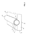
- Fig. 1 shows a schematic view of a collector element according to the invention.
- the collector element according to Fig. 1 comprises at least one, advantageously a plurality of parallel arranged absorber elements, in particular solar collector tubes 1 and a holder 2, which receives the solar collector tubes 1.
- the solar collector tubes 1 are preferably vacuum tubes 1, but other tubes are also conceivable.
- the term vacuum tubes therefore includes all solar collector tubes with absorber layers or absorber elements.
- the vacuum tube 1 comprises an inner tube 11 and an outer tube 12. Between the inner tube 11 and the outer tube 12, a gap 13 is formed, which is evacuated. Preferably, the internal pressure of the vacuum is less than 10 Pascal, in particular less than 0.1 Pascal. An absorber layer 10 for absorbing the heat of sunlight is arranged in this intermediate space 13, ie in a vacuum.
- the outer diameter of the vacuum tubes 1 is referred to as diameter D.
- the inner tube 11 consists of a good heat-conducting material. In particular, it may be a metal tube.
- the outer tube 12 is transparent in its direction of incidence of the solar radiation rectified side, ie substantially in the area 1 b. On the opposite side, the outer tube may be opaque.
- the vacuum tubes 1 of the collector element according to the invention are received by the holder 2 in such a way that the vacuum tubes come to lie next to one another.
- the vacuum tubes 1 are arranged at a distance A laterally spaced from each other.
- the vacuum tubes are parallel to each other.
- the vacuum tubes are preferably received over their entire length by the holder 2.
- the holder 2 is designed substantially as a cuboid and comprises a top 21, a bottom 22 and a plurality, here four, side walls 24.
- the side walls 24 connect the top 21 with the bottom 22.
- the holder 2 is made of a transparent, transparent or translucent Material. That is, sunlight incident on the holder 2 is guided inside the holder 2 due to its transparency.
- the translucent material of the holder 2 preferably has a refractive index n between 1.05 and 1.5.
- the bottom 22 may take a different shape than a flat shape.
- the bottom 22 is concave, convex, or parabolic, configured.
- the upper side 21 may, regardless of the configuration of the underside 22, over the entire width or only one entrance surface 25, also be configured concave or convex.
- the holder 2 made of Plexiglas or glass. These materials proved to be particularly robust against weather-related influences.
- materials are used which direct sunlight with a light transmission value (for example, according to ISO 13468-1 or DIN 5036-3) of more than 90%, in particular 92% or 93%, and are preferably temperature-resistant.
- the technology or the material of a fluorescence collector can be used.
- molecules may be embedded in the holder that fluoresce when exposed to sunlight, whereby, by total reflection, a large part of the incident light rays is conducted to the lower absorber layer surfaces where the light rays arrive concentrated. The efficiency is improved, especially in low-radiation environments.
- the grooves 20 extend from the top 21 into the holder 2 inside.
- the holder 2 preferably has a number of grooves 20 equal to the number of vacuum tubes 1.
- Each groove 20 is thus associated with a vacuum tube 1.
- the grooves 20 in the groove axis have a cross-section of the vacuum tube 1 complementary cross section, so that the vacuum tubes 1 can be inserted or embedded in the grooves 20. That is, in the present embodiment, that the grooves in cross section have the shape of circle segments. Circular segments which extend over an angle of 180 °, ie semicircular, or smaller than 180 °, are particularly advantageous.
- the process of replacement is very advantageous to the user, because it can replace defective vacuum tubes in a simple manner.
- the groove 20 has a length corresponding to the effective length of the vacuum tube.
- An effective length is understood to mean the length over which the absorption layer extends in the solar collector tube.
- the grooves 20 can be made into the holder 2 with high accuracy by a milling method.
- the surface of the groove 20 may be machined by grinding, polishing or lapping so that the surface of the groove 20 has a finer surface texture.
- This manufacturing method has the advantage that the vacuum tubes 1 can be inserted parallel to one another in the collector element with a high degree of accuracy. Alternatively, a plastic injection molding process can be used. This method also offers a high degree of accuracy.
- Fig. 3 the vacuum tubes 1 are shown with the same diameter D.
- the vacuum tubes 1 may also have different diameters D, wherein the groove 20 is adjusted according to the diameter D of the vacuum tube 1.
- the cuboid holder 2 upwardly delimiting area between the individual grooves is referred to as the entry surface 25.
- the entry surface 25 Via this entrance surface 25, rays S1, S2, S3 of the sunlight can enter the holder 2.
- the entry surface 25 may be planar, concave, as indicated by the entry surface 25 ', or convex.
- a flat entrance surface 25 is particularly advantageous, because this allows a particularly simple cleaning of the entry surface 25 and the part of the vacuum tubes 1, which protrudes beyond the entry surface 25.
- the entry surface 25 is preferably coated with a layer which is permeable to light rays in a first direction, so that therefore sunlight can enter the holder 2.
- a layer can be provided for example by suitable nanotechnology.
- the reflection of the rays S3 on the inside 25 of the holder 2 can then be increased. In other words, the reflection on the inside is greater than the size of the normally existing ones Rayleigh reflection can be increased.
- Nanoscale Laminated Layers is disclosed in Applied Physics Newsletter Volume 80, Number 14 .
- the groove 20 may be referred to as U-shaped. That is, the groove 20 has in a first section left and right on a flat side wall. In a second section, the side wall then turns into a semicircular shape. Accordingly, the second section begins from the bottom of the groove as seen at the height at which the center of the inserted vacuum tube comes to rest.
- the flat side wall can also be configured as a curved side wall. Further alternatives are also conceivable, provided that the first section does not narrow the cross section of the groove 20.
- the groove 20 thus has in the first section to a width which is equal to or greater than that Diameter of the vacuum tube 1, so that it can be inserted from above into the groove 20.
- the first portions can also extend at an angle, so that the shading of the vacuum tube 1 can be minimized.
- the grooves 20 are laterally spaced from each other.
- the distance is specified as distance A.
- the distance A is in particular smaller than the diameter D.
- the distance between the vacuum tubes can be chosen to be comparatively small, which means that the efficiency is greater compared to devices of the prior art.
- the holder 2 allows the arrangement of a larger number of vacuum tubes on the same collector surface. For vacuum tubes with a diameter of 38 mm, the distance A is therefore between 22.8 mm and 34.2 mm.
- a holder according to the invention has 13 to 16 grooves 20 over a width of one meter relative to a tube diameter of 38 mm.
- the reflector 3 which is equipped with a reflective layer, arranged.
- the reflective layer may also be referred to as a mirror layer become.
- the reflector 3 is used for reflection of the sunlight, which has entered the holder 2. By this reflection, it is possible to irradiate the lower part 1a of the vacuum tube 1 with sunlight. The lower part 1a is thus indirectly supplied with the sunlight.
- a second embodiment is shown.
- Like reference numerals designate the same or similar features in all figures.
- the outer tube 12 and the holder 2 form a single element, the housing 30th Then the holder 2 is off Fig. 1 no solid material element, but a, for example, cuboid forms the bottom part of the housing 32.
- the reference numeral 31, the tubular part of the housing is designated.
- the inner tube 11 is disposed within an evacuated housing 30 from.
- the absorber layer 10 is protected in this evaluated space 13.
- the absorber layer 10 is arranged around the entire tube in cross section over a substantial portion of the length of the tube.
- the top of the outer tube 12 may be configured even with the housing 30. It is essential that the heat-transferring fluid is disposed within the inner tube 11.
- the insertion of a further tube 300 can also be considered here Fig. 5 be turned off.
- This embodiment also belongs to the combination of the invention.
- the reflector 3 may be disposed directly on the underside 22 of the holder 2 or the housing 30.
- the reflector 3 is preferably an aluminum sheet with an anodized coating. Such an aluminum sheet may be adhered or otherwise secured to the underside 22 of the holder. Alternatively, the aluminum sheet can also be poured or embedded in the holder 2.
- the provision of the reflector within the housing 30 after Fig. 2 also protects the reflector. It is also possible, the lower part of the housing 30 opaque, preferably as a reflector, form and only the upper portion transparent.
- the reflector 3 may also be a mirror layer, which is applied directly to the underside 22 of the holder 2 by a vapor deposition method. Accordingly, the reflector 3 is a thin layer on the underside 22 of the holder 2.
- a vapor deposition method proves to be particularly advantageous because the coating can be applied in concave or convex or parabolic or planar configurations of the bottom 22 in an efficient manner.
- the reflective layer on a carrier, not shown.
- the carrier and the reflective layer are referred to as a reflector.
- This carrier is embedded or cast in the lower part of the holder 2. This means in this case that the carrier with the reflector layer is completely absorbed by the holder. In other words, the reflector is completely surrounded by the holder 2 here.
- the described attachment of a reflector layer has the advantage that the reflector layer 3 is protected by the holder 2 from the weather conditions described in the introduction.
- the reflector layer can thus retain a lasting surface quality over the life of the collector element.
- the side walls 24 are also provided with a reflective layer, preferably analogously to the underside 22. Accordingly, rays which impinge on the side walls 24 from the interior of the holder 2 are reflected on the side walls 24. The Rays that have entered the holder 2, so can not escape through the side walls 24.
- the side walls 24 with solar cells or photovoltaic cells, wherein the reflector layer is replaced with these cells at least partially or completely. With the solar cells electrical energy can then be provided, which supply, for example, the circulation pump for the heat transfer medium and / or the control electronics.
- Fig. 4 are three side by side in the holder 2 lying vacuum tubes 1 shown in a sectional view. Also here the incident sunlight is shown as rays S1, S2 and S3.
- the rays S1 indicate the upper part 1b of the vacuum tube 1.
- the beam S2 enters the holder 2 through the entrance surface 25 and is reflected at the reflector layer 3, thus indirectly illuminating the lower part 1a of the vacuum tube.
- the beam S3 enters the holder 2 through the entry surface 25 and is reflected at the reflector layer 3. In the course of the beam S3 is then reflected again on the inside at the entrance surface. By a further reflection on the reflector layer 3, the beam can then reach the lower part 1a of the vacuum tube 1 indirectly.
- the vacuum tubes 1 are not irradiated by a specific sector here, as is the case with a reflector of the prior art. If the sun is shallow, it may be that the vacuum tube indirectly from below via an entrance surface 25, which is not directly adjacent to the corresponding vacuum tube is irradiated. Thus, in low sunshine, a greater proportion of the beams can be used, as in collector systems of the prior art. The efficiency is therefore increased.
- the holder 2 may be filled with a preferably colorless medium, such as a fluid, a gas or a vacuum.
- a preferably colorless medium such as a fluid, a gas or a vacuum.
- the grooves 20, the top 21, the bottom 22 and the side walls 24 form a kind of shell or hollow body, which can absorb the fluid, the gas or the vacuum.
- the medium is a fluid, it must be chosen so that it does not freeze in winter and damage the shell.
- Such fluids are known in the art.
- water is used with ethylene glycol, water with hexanol, or other ethanols.
- the fluid may also be a synthetically produced oil.
- the reflection layer can be mounted both on the outside and on the cavity or interior facing surface.
- the holder 2 may also be designed as a shell.
- the top 21 of the holder 2 has in this embodiment a rectangular opening and the corresponding side walls 24 have a semicircular opening, so that forms a kind of open groove.
- the vacuum tube 1 can then be inserted into this open groove and connected by means of an adhesive with the side edges.
- the adhesive takes over the sealing effect at the same time.
- the bottom 22 and optionally the side walls 24 may be made of a metallic material, for example a deep-drawn or stamped metal sheet.
- the top 21 is here from one of the above Materials.
- the bottom 22 and sidewalls 24 form a type of pan which can receive the fluid, gas or vacuum.
- the tub With the lid, the tub can be completed and thus a hollow body is provided.
- the surface of the side walls 24 and the bottom 22, which face the interior of the hollow body, may be polished or provided with the reflection layer. By arranging the reflection layer on the side facing the interior, this is well protected against the effects of weather.
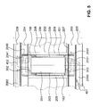
- Fig. 4 and 5 show a collector element according to the invention K according to a further embodiment of the invention, as shown Fig. 5 visible at least one absorber element 100 and a holder 200 includes. Furthermore, the collector element advantageously comprises a heat storage element 300 assigned to each absorber element 100.
- the holder 200 preferably comprises a holder body 201, which may also be referred to as a light guide body due to its light-conducting property.
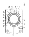
- the holder body 201 preferably has the shape of a cuboid and thus has according to Fig. 6 a bottom 2010, two side surfaces 2011, a top 2012, a bottom front side 2013 and a top front side 2014 on. Sunlight can enter the holding body 201 via the upper side 2012.
- the collector element K or the holder body 201 has at least two cylindrical openings 202.
- the openings 202 extend, preferably parallel to one another, from the lower end face 2013 to the upper end face 2014 through the holder body 201.
- the cylindrical openings 202 serve to receive one absorber element 100 each.
- the holder body 201 is made of a transparent or translucent material, such as Plexiglas, Glass or other suitable materials which guide the sunlight with a transmittance of over 90% and are preferably temperature resistant.
- the holder body 201 may be filled with a fluid or gas, wherein the boundary surfaces of the holder body 201 form a hollow body.
- the underside 2010 as well as the two short side surfaces 2011 and the lower end side 2013 as well as the upper end side 2014 of the holder body 201 are preferably provided with a reflection layer or mirror layer.
- This reflection layer serves to reflect the incident sunlight.
- the reflection layer can be applied for example by a vapor deposition method. If the holder body 201 is formed as a hollow body, the reflection layer or the mirror layer can be arranged both on the outside and on the inside, which faces the inside of the cavity.
- a vapor-deposited coating has the advantage that the configuration of the lower surface 2010 may be flat, convex, concave or parabolic. A tedious deformation of any reflector sheets, as is the case with collector elements from the state, is omitted in this holding body.
- the mirror layer may have a suitable rough surface in order to allow diffuse scattering of the incident solar rays. It is also very small spherical particles in the edge zones of the light guide body in the immediate vicinity of the mirror layer surfaces are introduced, so that a Rayleigh scattering / reflection. The just described Treatment of the reflection layers allows more effective irradiation of the rear surfaces of the absorber elements 100.
- the coating can also be designed as a polished sheet metal.
- the mirror layers or reflection layers also prevent long-term moisture absorption by the material.
- the light entrance surface 2012 can be treated and sealed on the basis of chemical nanotechnology, so that the adhesion of dirt and foreign substances is virtually prevented and also in the long run, the beading of water is ensured.
- a first inner profile element 203 and on the upper end side 2014 a second inner profile element 204 is arranged.
- the inner profile elements 203, 204 preferably extend over the entire surface of the end faces 2013, 2014.
- a first outer profile element 205 and on the second inner profile element 204 a second outer profile element 206 is arranged.
- the inner and outer profile elements 203, 204, 205, 206 are connected to each other and to the holder body 201 by means of a screw connection.
- the profile elements 203, 204, 205, 206 are made of a plastic, such as PMMA or PEEK, or a metal, such as aluminum.
- the lower end side 2013 of the holder body 201 has a groove 207 which extends from the end face 2013 into the holder body 201 extends into it. Further, the groove 207 is arranged such that the groove 207 connects all cylindrical openings 202 with each other. Preferably, the groove 207 is configured in its cross section as a semicircular. Other cross-sectional shapes, such as rectangular or square, are also conceivable.
- the groove 207 preferably extends into the front side 2013 only over a small depth. The depth of the groove 207 is chosen so that the air can be removed as easily and efficiently from the cavity in the production of the vacuum.
- a seal is preferably arranged between the lower end face 2013 and the first inner profile element 203, and between the upper end face 2014 and the second inner profile element 204.
- the seal can be achieved, for example, by a coating of the end faces 2013, 2014.
- an elastic seal in corresponding wells, not shown, can be embedded. Due to the evacuation of cavities described below, which are limited inter alia by the profile elements, a particularly durable design of the seal is necessary.
- a modified inventive collector element is shown in a view from the front.
- the cylindrical openings 202 have a diameter D and are laterally spaced from each other.
- the distance is specified as distance A.
- the distance A is in particular smaller than the diameter D of the cylindrical opening 202.
- the distance between the cylindrical openings 202 can be chosen to be comparatively small, which means that the efficiency is greater compared to devices of the prior art.
- the holder body 201 allows the arrangement of a larger number of cylindrical openings on the same collector surface. For cylindrical openings with a diameter of 38 mm, the distance A is therefore between 22.8 mm and 34.2 mm.
- a holder 200 according to the invention has 13 to 16 cylindrical openings 202 over a width of one meter.
- the cylindrical openings are preferably arranged centrally or centrally.
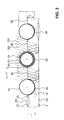
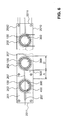
- Fig. 7 shows a part of the Fig. 6 wherein the arrangement of the absorber element 100 in the holder body 201 and the heat storage element 300 in the absorber element 100 is shown by way of example. A plan view of the arrangement is shown in FIG Fig. 5 shown.
- the cylindrical opening 202 is delimited by a hollow cylindrical jacket surface 2020.
- the absorber element 100 is here arranged concentrically in the cylindrical opening 202 by means of means described below. An eccentric arrangement is also possible.
- the absorber element 100 or the length of the absorber layer has substantially the same length as the cylindrical opening 202.
- the absorber element 100 may also be configured shorter or longer than the cylindrical opening 202.
- the absorber element 100 preferably comprises an absorber layer 101 and the absorber tube 102.
- the absorber layer 101 is arranged on the outside of the absorber tube 102.
- the absorber element 100 has a maximum outer diameter which is smaller than the diameter D of the cylindrical opening 202.
- an annular gap 208 is created between the lateral surface 2020 of the cylindrical opening 202 and the absorber layer 101.
- the annular gap 208 forms part of the resulting cavity 209, which is bounded below by the first inner profile element 203 and at the top by the second inner profile element 204. This cavity 209 can be evacuated.
- the absorber tube 102 is preferably made of a good heat-conducting material, such as a metallic material. Especially suitable is copper, aluminum, brass or stainless steel.
- the absorber layer 101 can for example be vapor-deposited on the absorber tube 102 or pressed on as a thin film.
- the absorber layer 101 is made of tin oxide (titanium oxide), metal carbide, black chrome, or black paint. Since the absorber layer 101 is in a vacuum, it is protected from any wear. In addition, occur due to the vacuum virtually no heat loss to the environment.
- the absorber layer may also be selectively coated.
- Such selective coatings have the advantage that the heat losses can be reduced by thermal radiation.
- Such selective coatings are known to the person skilled in the art.
- the absorber element 100 is mounted in an annular groove 2030 in the first inner profile element 203 and in an annular groove 2040 in the second inner profile element 204.
- the annular grooves 2030, 2040 are wetted prior to insertion of the absorber element 100 with a permanently elastic silicone adhesive or with a silicone sealant.
- the inner profile elements 203, 204 define the cavity 209 to be evacuated.
- the cavity 209 to be evacuated consists essentially of the cavity which arises through the annular gap 208 and the grooves 207.
- the internal pressure of the vacuum is less than 0.1 pascal.
- the vacuum space can also from the entire housing 30 from Fig. 2 consist.
- Essential is only the sequence (upwardly transparent) vacuum housing 11, vacuum space 13, absorber layer 101 on thermally conductive tube 100 with internal fluid path, which may still have an inner tube 300 with optional latent memory 301.
- the collector element has an evacuation port 210 which, for example, in FIG Fig. 3 is apparent.
- the evacuation port is connected to the cylindrical openings 202 via the groove 207. That is, via the evacuation port 210, the air, which is located in annular gaps 208 and in the groove 207, can be removed.
- the evacuation port 210 is closed with a suitable shut-off valve.
- the heat storage element 300 can be seen.
- the heat storage element 300 is preferably a hollow body which can be filled with a heat storage medium and has a cavity 301.
- the hollow body is essentially cylindrical. Accordingly, the hollow body comprises a tubular hollow body side wall 303 and two hollow body cover 302, which are arranged on the front side of the hollow body wall 303.
- the outer diameter of the heat storage element 300 is selected to be smaller than the inner diameter of the absorber tube 102.
- the heat storage element 300 is mounted concentrically in the absorber tube 102 with centering cams 400.
- the centering cams 400 are preferably welded to the absorber tube 102 or to the hollow body side wall 303 and configured such that the heat storage element 300 can be held by a holding force resulting from a static friction force.
- three centering cams 400 per bearing point are arranged at an angle of 120 °. Over the entire length of the heat storage element 300 several such bearings are arranged.
- the concentric mounting of the heat storage element 300 in the absorber tube 102 creates an annular gap-shaped intermediate space 103.
- This intermediate space 103 can be flowed through by a heat transfer medium.
- a heat transfer medium In particular, so that the heat transfer amount can be concentrated on a near-absorbent area, namely an annular gap.
- Within the heat storage tube 300 may be air, it may be a latent storage material or - somewhat less favorable - vacuum or other substance.
- the advantage of this medium in space 301 is its isolation via the heat transfer medium in space 103. This medium in 301 is not in contact with "cold" elements, but is in easily accessible equilibrium with the amount of heat absorbed by the absorber.
- the cavity 301 of the heat storage element 300 which may also be called a latent heat store, is filled up with a phase change material or a phase change material.
- a phase change material for example, microencapsulated paraffin or microencapsulated paraffin beads are suitable. These waxy materials can store heat reversibly.
- the absorber elements 100 absorb solar energy, ie heat
- the heat is transferred to the heat transfer medium which flows in the intermediate space 103.
- heat is also partially transferred to the heat storage element 300, wherein the phase change material also heats up.
- the phase change material changes its state and liquefies. In other words, this means that part of the heat energy present by the solar radiation is absorbed by the heat transfer medium and another part by the phase change material.
- the heat energy is stored by the phase change material and can be delivered at a time in which the solar radiation decreases or no longer exists. This can be the case, for example, during a change in the weather or at night.
- the phase change material solidifies.
- the phase change material has a melting point which is between 20 ° C and 90 ° C.
- the geographic location is crucial for the choice of the melting point.
- a phase change material with a higher melting point is used than for layers with lower average temperatures.
- Other requirements criteria, such as the operating temperature of the heat transfer medium also influence the choice of the phase change material.
- the melting point temperature is slightly greater, for example 3 ° C to 10 ° C, than the optimum operating temperature.
- the inner profile elements 203, 204 each have a through opening 2031, 2041 on.
- the outer profile elements 205, 206 each have a channel 2050, 2060.
- the cold heat transfer medium may for example result from a heat exchanger and is represented by the arrows 401.
- the cold heat transfer medium 401 thus enters through the channel 2050 via the opening 2031 in the gap 103 a.
- the heat transfer medium 401 can absorb heat, which is provided by the absorber element 100 and by the heat storage element 300.
- the warm heat transfer medium 402 leaves the gap 103 via the opening 2041 and can be directed into the channel 2060. Via a connection element 211, like this one in FIG Fig. 3 is shown, the warm heat transfer medium may for example be supplied to a heat exchanger.
- the surfaces can, for example, be provided with a metallic coating be provided. Thereby, a passage of water vapor can be reliably prevented.
- a temperature sensor 212 which can measure the temperature of the heat transfer medium.
- the output temperature of the heat transfer fluid can be monitored.
- This variable can be used as a control variable, so that a protective tarpaulin 505 can be pulled over the top of the collector, for example in the event of failure of the circulation pump for the heat transfer medium, for example water, so that no further significant heat input occurs.
- the tarpaulin is opaque and has an insulating effect.
- a buffer battery can be provided for the drive so that it can still control this movement even in the event of a power failure.
- the latent storage is a good preventive measure against overheating of the system. Furthermore, excess energy can be delivered to peripheral devices such as a heater, etc. Furthermore, a protective device may be provided, which by means of Fig. 9 to 11 is described.
- the coaxial arrangement of the absorber tube 102 and the heat storage element 300 in the cylindrical aperture 202 allows for optimal design of the gap 103 by the flexible selection of different diameters of the coaxially arranged tubes for the most efficient implementation of solar energy.
- the heat transfer medium flows through the intermediate space 103 in a turbulent flow
- the heat exchange between the absorber pipe 102 and the heat transfer fluid can take place in a particularly efficient manner.
- the turbulent flow can, for example be achieved by the arrangement of the centering cam 400. Alternatively, mixing elements can also be provided.
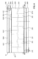
- Fig. 8 the beam path of sunlight is shown, which is incident in the cuboid holder body 201 over the top 2012.
- the top 2012 can also be referred to as entrance area. Via this entrance surface 2012, rays S100, S200, S300 of the sunlight can enter the holder body 201.
- the entrance surface 2012 may be flat, concave or convex. A flat entrance surface 2012 is particularly advantageous because this allows a particularly simple cleaning of the entrance surface 2012.
- the entrance surface 2012 is preferably coated with a layer which is permeable to light rays in a first direction, so that therefore sunlight can enter the holder body 201.
- the entrance surface 2012 may be provided with a nano-coating described above with the aid of the first embodiment. All of the embodiments disclosed in this description can be connected or combined as desired either completely or only partially.
- the rays S100 indicate the upper part 100b absorber element 100th
- the beams S200 enter the holder body 201 through the entrance surface 2012, and are reflected on the reflector layer disposed on the lower side 2010, thus indirectly exposing the lower portion 100a of the absorber element 100.
- the beam S300 enters the holder body 201 through the entrance surface 2012 and is reflected on the reflector layer disposed on the lower side 2010. In the further course of the beam S300 is then reflected on the inside at the entrance surface 2012 again. As a result of the renewed reflection on the inside of the entrance surface 2012, the beam S300 illuminates the absorber element 100 from above.
- the absorber elements 100 are not irradiated by a specific sector here, as is the case with a reflector of the prior art. If the sun is shallow, it may be that the vacuum tube is indirectly irradiated from below via an entrance surface 2012, which is not directly in the region of the corresponding absorber element 100. Thus, in low sunshine, a greater proportion of the beams can be used, as in collector systems of the prior art. The efficiency is therefore increased.
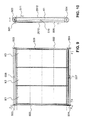
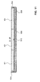
- Figs. 9 to 11 show an arrangement of a plurality of collector elements K1, K2, K3 with a cover device 500.
- the collector elements K are preferably configured as described above.
- Such a cover device 500 prevents damage to a collector element K or to an arrangement of a plurality of collector elements K1-K3 according to the invention. Damage can be caused, for example, by weather events such as hail, storm, snow, etc., overheating if the heat consumption of a heat exchanger connected to the collector element is too low or due to power failure (threatening) or.
- the cover device 500 comprises a drive device 501, a drive belt 502, driven pulleys 503, deflection pulleys 504 and a protective cover 505, which may also be referred to as protective tarpaulins.
- the protection panel 505 is disposed parallel to the surface of the collector elements and extends over the entire surface of the collector elements K1, K2, K3 if the surface of the collector elements is to be covered by the protection panel 505.
- the protective cover 505 is configured as a circumferential protective cover, that is to say the protective cover moves downwards on the upper side 2012 and upwards again on the underside of the cover.
- the protection panel 505 may also be driven in two directions.
- the protective cover 505 is disposed below or behind the collector elements K1, K2 and K3, ie on the bottom side 2010, if they are to absorb heat.
- the protective tarpaulin 505 has a length in the direction of flow, which corresponds to the distance between the two deflection / pulleys 503 and 504, so that it is either stretched on top of 2012 protective before the collector or - for example, for drying - behind the bottom 2010 is stretched behind the collector.
- the protective cover 505 can be stretched by the lateral guides or by clamping a transverse web, with which the flexible tarpaulin is pulled along.
- the driven pulleys 503 are above the collector element assembly and the diverting pulleys 504 are disposed below the collector element assembly.
- two pulleys 503 and two guide pulleys 504 are arranged.
- the two pulleys 503 and the two deflection pulleys 504 can be connected via common axes.
- the drive belt 502 is driven by the driven pulley 503 and deflected by the deflection pulley 504.
- the protective panel 505 is connected to the drive belt 502 and can be driven by it. As soon as the drive device 501 receives a corresponding control command, the drive belt 502 or the protective cover 505 is driven via the drive pulley 503. Thereby, the protection panel 505 can be moved up or down.
- the protective cover 505 may have cleaning bristles 506.
- This cleaning bristles 506 slide on a movement of the protective cover 505 over the surface of the individual collector elements and thus clean the surfaces.
- Such cleaning bristles 506 are particularly advantageous in the removal of dust, dirt particles, snow, etc.
- various sensors can be arranged. These sensors detect actual conditions of the environment. As soon as an actual state reaches or exceeds a predetermined desired state, the process of covering or uncovering the collector elements can be triggered.
- the corresponding desired states can be stored, for example, in a solar controller.
- a Photosensor 509 measures the brightness of the radiation on the collector elements.
- a hail sensor 510 detects emerging hailstorm.
- the values measured by the sensor are compared with predetermined reference values.
- the drive device 501 is supplied with the corresponding command and the protective plate 505 is pulled over the collector elements K1 to K3.
- the drive system receives the command to retract the protective cover so that the collector elements K1 to K3 can again absorb the solar energy.
- Another sensor may be, for example, a snow sensor.
- the differently constructed snow sensors 507 and 508 first register readings by relative darkening of their cell surfaces, which are compared with the readings from the photosensor 509 along with stored and predetermined reference values.
- the reflections of the built-in light emitting diodes (LED) in the snow sensors are evaluated. If then the electronic evaluation in the solar controller the initial snowfall then the bristles 506 mounted on the back of the guard are once wiped off the entire surface of the collector elements.
- the amount of snow wiped off the surface is deposited on one of the two snow sensors, which is decisive for the evaluation.
- the measured values are buffered.
- the protective cover can cover the surface of the collector elements. If only a small amount of snow is detected, the wiping operations can be repeated several times.
- the protective cover 505 After sunrise, depending on the month, orientation and inclination of the collector elements, a certain amount of time passes until the snow sensors register the solar beams and then output the corresponding signal to the drive device 501 so that the protective cover 505 can be removed from the surface of the collector elements.
- the guard panel 505 then moves down intermittently to allow the overlying snow masses to slide off. If the protection panel 505 has a nano-coated surface, the snow masses can slide off particularly well.
- the solar controller can measure the load current of the electric motor.
- the load current can be considered as an indirect indicator of the snow load or the thickness of the snow layer.
- the electric motor is accelerated jerkily and stopped after a short time and is then accelerated again jerkily until the load current drops to ever smaller values and finally the normal load current without snow load from the solar controller is detected as an indirect indicator of snow clearance.
- This movement allows a better sliding of the snow masses of the protection panel 505 down to the roof surface without in To make this area an obstructive ever higher pile, because here, too, the sliding snow masses are repelled one behind the other.
- the solar controller is programmed so that the top collector element is controlled first and the lowest collector element last. This means that the topmost collector element is first cleared of snow.
- the protective panel 505 is again positioned below the collector members in the original position by means of magnetic sensors and distance-measurement induction strips mounted between the inside of the drive pulley 503 and the motor flange.
- the protective device reliably prevents damage to the collector elements described above and protects the collectors from hail damage, prevents snow covers on collectors; Furthermore, a self-cleaning is possible in the event of contamination.
- the protection device may be provided with a backup battery, not shown, which ensures an emergency power operation in case of power failure.
- the collector elements are covered, for example, after 30 seconds, if a minimum brightness in the daytime mode is measured by means of the photosensor.
- the back-up battery of the emergency power supply reaches a critical range of undervoltage (eg 11.7 or 23.4 V DC).
- a critical range of undervoltage eg 11.7 or 23.4 V DC
- the field module is covered with the protective cover after one hour, for example.
- the audible and visual warning signals are only switched off with an acknowledgment.
- the controller In solar operation, the controller (boiler room) constantly compares the differential temperature ⁇ t between the collector temperature and the storage tank temperature of the latent storage tank. If, over a certain period of time, it tends to increase too fast and is above the fixed reference value, the field module is covered with the protective field until the further measured ⁇ t values return to their normal range.
- the guides can be formed by the pulleys and pulleys 503/504, because if they are driven directly and the tarpaulin 505 is braced over this, this direct drive over the length of the solar element is possible if the circle running through corresponding outside of the solar panels Ribbons is closed. It is also possible to provide lateral guides, which then integrate according to the drive belt 502 on which the tarpaulis is laterally attached or at least guided. It may be that at one or more specific points of these belts have these at opposite locations on transverse drive bars, which are attached to this, to which corresponding sections of the tarpaulin 505 are firmly connected.
- a tension-resistant tear-resistant tarpaulin can be moved as a cover and protection against the solar panels and on the other hand, this tarpaulin is stowed behind the solar panels.
- tarpaulin materials can be used, as they are used in truck tarpaulins or tents.
Landscapes
- Engineering & Computer Science (AREA)
- Physics & Mathematics (AREA)
- Life Sciences & Earth Sciences (AREA)
- Sustainable Development (AREA)
- Sustainable Energy (AREA)
- Thermal Sciences (AREA)
- Chemical & Material Sciences (AREA)
- Combustion & Propulsion (AREA)
- Mechanical Engineering (AREA)
- General Engineering & Computer Science (AREA)
- Roof Covering Using Slabs Or Stiff Sheets (AREA)
- Optical Elements Other Than Lenses (AREA)
Priority Applications (1)
| Application Number | Priority Date | Filing Date | Title |
|---|---|---|---|
| EP08157819.7A EP2000748A3 (fr) | 2007-06-06 | 2008-06-06 | Elément de collecteur destiné au gain de chaleur à partir du rayonnement solaire et couverture de protection correspondante |
Applications Claiming Priority (2)
| Application Number | Priority Date | Filing Date | Title |
|---|---|---|---|
| EP07109728 | 2007-06-06 | ||
| EP08157819.7A EP2000748A3 (fr) | 2007-06-06 | 2008-06-06 | Elément de collecteur destiné au gain de chaleur à partir du rayonnement solaire et couverture de protection correspondante |
Publications (2)
| Publication Number | Publication Date |
|---|---|
| EP2000748A2 true EP2000748A2 (fr) | 2008-12-10 |
| EP2000748A3 EP2000748A3 (fr) | 2014-04-02 |
Family
ID=38698700
Family Applications (1)
| Application Number | Title | Priority Date | Filing Date |
|---|---|---|---|
| EP08157819.7A Withdrawn EP2000748A3 (fr) | 2007-06-06 | 2008-06-06 | Elément de collecteur destiné au gain de chaleur à partir du rayonnement solaire et couverture de protection correspondante |
Country Status (1)
| Country | Link |
|---|---|
| EP (1) | EP2000748A3 (fr) |
Cited By (4)
| Publication number | Priority date | Publication date | Assignee | Title |
|---|---|---|---|---|
| WO2013091289A1 (fr) * | 2011-12-19 | 2013-06-27 | 北京和能通源科技有限公司 | Plaque de collecte d'énergie composite de l'espace |
| WO2015103559A1 (fr) * | 2014-01-06 | 2015-07-09 | Skyfuel, Inc. | Récepteurs linéaires pour capteurs solaires |
| CN113686027A (zh) * | 2020-04-14 | 2021-11-23 | 浙江宝威电气有限公司 | 能对热管吸热端进行清洁的反光跟踪太阳能热管加热装置 |
| WO2026061622A1 (fr) * | 2024-09-19 | 2026-03-26 | Luketina Igor | Dispositif pour au moins un module solaire |
Citations (7)
| Publication number | Priority date | Publication date | Assignee | Title |
|---|---|---|---|---|
| GB2058332A (en) | 1979-09-10 | 1981-04-08 | Exxon Research Engineering Co | Radiation Collector |
| US4324947A (en) | 1979-05-16 | 1982-04-13 | Dumbeck Robert F | Solar energy collector system |
| US4508426A (en) | 1983-05-12 | 1985-04-02 | Hutchison Joseph A | Locking means for solar collector |
| RU1614606C (ru) | 1988-09-29 | 1994-11-15 | Беляев Юрий Михайлович | Устройство для защиты гелиоустановки от атмосферных воздействий |
| DE10317479A1 (de) | 2003-04-16 | 2004-11-11 | Institut für Luft- und Kältetechnik gGmbH | Abreinigungsanlage für Photovoltaik-Generatoren und Sonnenkollektoren |
| DE202006003697U1 (de) | 2006-03-09 | 2006-05-04 | Schulz, Eberhard | Vorrichtung zur Reinigung von Solarzellen |
| EP1707897A1 (fr) | 2003-12-03 | 2006-10-04 | Dynax Corporation | Panneau solaire |
Family Cites Families (8)
| Publication number | Priority date | Publication date | Assignee | Title |
|---|---|---|---|---|
| DE7537207U (de) * | 1975-11-22 | 1976-04-22 | Brown, Boveri & Cie Ag, 6800 Mannheim | Bauelement fuer einen solarkollektor |
| AT374910B (de) * | 1978-03-07 | 1984-06-12 | Rodler Ing Hans | Aus durchsichtigen rohren gebildeter sonnenkollektor |
| GB2048459A (en) * | 1979-05-03 | 1980-12-10 | Gunderson C F | Solar heat collectors |
| JPS58133561A (ja) * | 1982-02-03 | 1983-08-09 | Pentel Kk | 潜熱蓄熱型太陽熱コレクタ |
| US4440154A (en) * | 1982-06-25 | 1984-04-03 | Gte Laboratories Incorporated | Solar energy collecting apparatus |
| DE29801682U1 (de) * | 1998-02-02 | 1998-03-19 | Freimund, Wolfgang, 22179 Hamburg | Thermischer Sonnenröhrenkollektor in Flachbauweise |
| DE19818773A1 (de) * | 1998-04-27 | 1999-11-04 | Peter Lutz | Solarkollektorelement und Solarkollektor mit einer Mehrzahl derartiger Elemente |
| ES2306356T3 (es) * | 2006-02-24 | 2008-11-01 | Raymond Mattioli | Captador solar de concentracion. |
-
2008
- 2008-06-06 EP EP08157819.7A patent/EP2000748A3/fr not_active Withdrawn
Patent Citations (7)
| Publication number | Priority date | Publication date | Assignee | Title |
|---|---|---|---|---|
| US4324947A (en) | 1979-05-16 | 1982-04-13 | Dumbeck Robert F | Solar energy collector system |
| GB2058332A (en) | 1979-09-10 | 1981-04-08 | Exxon Research Engineering Co | Radiation Collector |
| US4508426A (en) | 1983-05-12 | 1985-04-02 | Hutchison Joseph A | Locking means for solar collector |
| RU1614606C (ru) | 1988-09-29 | 1994-11-15 | Беляев Юрий Михайлович | Устройство для защиты гелиоустановки от атмосферных воздействий |
| DE10317479A1 (de) | 2003-04-16 | 2004-11-11 | Institut für Luft- und Kältetechnik gGmbH | Abreinigungsanlage für Photovoltaik-Generatoren und Sonnenkollektoren |
| EP1707897A1 (fr) | 2003-12-03 | 2006-10-04 | Dynax Corporation | Panneau solaire |
| DE202006003697U1 (de) | 2006-03-09 | 2006-05-04 | Schulz, Eberhard | Vorrichtung zur Reinigung von Solarzellen |
Cited By (7)
| Publication number | Priority date | Publication date | Assignee | Title |
|---|---|---|---|---|
| WO2013091289A1 (fr) * | 2011-12-19 | 2013-06-27 | 北京和能通源科技有限公司 | Plaque de collecte d'énergie composite de l'espace |
| WO2015103559A1 (fr) * | 2014-01-06 | 2015-07-09 | Skyfuel, Inc. | Récepteurs linéaires pour capteurs solaires |
| CN106030218A (zh) * | 2014-01-06 | 2016-10-12 | 天空燃料有限公司 | 用于太阳能收集器的线性接收器 |
| US20160327312A1 (en) * | 2014-01-06 | 2016-11-10 | Skyfuel, Inc. | Linear receivers for solar collectors |
| CN113686027A (zh) * | 2020-04-14 | 2021-11-23 | 浙江宝威电气有限公司 | 能对热管吸热端进行清洁的反光跟踪太阳能热管加热装置 |
| CN113686027B (zh) * | 2020-04-14 | 2023-09-29 | 浙江宝威电气有限公司 | 能对热管吸热端进行清洁的反光跟踪太阳能热管加热装置 |
| WO2026061622A1 (fr) * | 2024-09-19 | 2026-03-26 | Luketina Igor | Dispositif pour au moins un module solaire |
Also Published As
| Publication number | Publication date |
|---|---|
| EP2000748A3 (fr) | 2014-04-02 |
Similar Documents
| Publication | Publication Date | Title |
|---|---|---|
| EP0767889B1 (fr) | Dispositif pour la production d'energie a partir de la lumiere solaire, comportant au moins un collecteur solaire | |
| EP0029442B1 (fr) | Installation pour la commande automatique du flux solaire incident | |
| DE102005006329B4 (de) | Solaranlage | |
| CH619769A5 (fr) | ||
| WO2006106139A1 (fr) | Collecteur solaire | |
| DE102008029676B4 (de) | Sonnenkollektor mit mikrostrukturierter Absorberfläche | |
| EP2000748A2 (fr) | Elément de collecteur destiné au gain de chaleur à partir du rayonnement solaire et couverture de protection correspondante | |
| DE2933089A1 (de) | Sonnenwaermekollektor | |
| WO2002084182A1 (fr) | Collecteur solaire | |
| DE102007048460B4 (de) | Vorrichtung zur Gewinnung von Solarenergie | |
| DE102008047327B4 (de) | Sonnenenergiemodul und Sonnenenergiemodulanordnung | |
| DE10034683C1 (de) | Kompakte Solaranlage zur Brauchwassererwärmung | |
| DE102010018632B4 (de) | Solarbetriebener Luftkollektor | |
| DE202005007474U1 (de) | Leichter Sonnenkollektor mit integriertem Überhitzungsschutz | |
| DE19505857A1 (de) | Sonnenkollektorelement | |
| DE102004020850B4 (de) | Röhrenkollektor zur Absorption von Lichtenergie | |
| EP2463601A2 (fr) | Élément de fassade solaire, système der fassade solaire | |
| DE19614787A1 (de) | Gebäudeklimatisierungssystem mit Einrichtungen zur Konzentration von Sonnenstrahlung | |
| DE20220874U1 (de) | Sonnenkollektor | |
| DE202007003078U1 (de) | Flacher Solarkollektor zur Konzentration | |
| DE3101186A1 (de) | Sonnenwaermekollektor mit absorber und fluidem waermetraeger | |
| DE4444104C1 (de) | Wärmeschutz mit passiver Solarenergienutzung | |
| DE10045029C1 (de) | Vorrichtung zur Nutzung von Solarenergie und zum Anbringen an eine Außenwand- oder Dachfläche eines Gebäudes | |
| DE3144807A1 (de) | Anlage zum wenigstens teilweisen decken des energiebedarfs (waerme) von raeumen | |
| EP0231225A1 (fr) | Chauffage solaire pour batiments |
Legal Events
| Date | Code | Title | Description |
|---|---|---|---|
| PUAI | Public reference made under article 153(3) epc to a published international application that has entered the european phase |
Free format text: ORIGINAL CODE: 0009012 |
|
| AK | Designated contracting states |
Kind code of ref document: A2 Designated state(s): AT BE BG CH CY CZ DE DK EE ES FI FR GB GR HR HU IE IS IT LI LT LU LV MC MT NL NO PL PT RO SE SI SK TR |
|
| AX | Request for extension of the european patent |
Extension state: AL BA MK RS |
|
| RIC1 | Information provided on ipc code assigned before grant |
Ipc: F24J 2/04 20060101AFI20131030BHEP |
|
| PUAL | Search report despatched |
Free format text: ORIGINAL CODE: 0009013 |
|
| AK | Designated contracting states |
Kind code of ref document: A3 Designated state(s): AT BE BG CH CY CZ DE DK EE ES FI FR GB GR HR HU IE IS IT LI LT LU LV MC MT NL NO PL PT RO SE SI SK TR |
|
| AX | Request for extension of the european patent |
Extension state: AL BA MK RS |
|
| RIC1 | Information provided on ipc code assigned before grant |
Ipc: F24J 2/04 20060101AFI20140221BHEP |
|
| 17P | Request for examination filed |
Effective date: 20140809 |
|
| RBV | Designated contracting states (corrected) |
Designated state(s): AT BE BG CH CY CZ DE DK EE ES FI FR GB GR HR HU IE IS IT LI LT LU LV MC MT NL NO PL PT RO SE SI SK TR |
|
| AKX | Designation fees paid |
Designated state(s): AT BE BG CH CY CZ DE DK EE ES FI FR GB GR HR HU IE IS IT LI LT LU LV MC MT NL NO PL PT RO SE SI SK TR |
|
| AXX | Extension fees paid |
Extension state: AL Extension state: BA Extension state: RS Extension state: MK |
|
| STAA | Information on the status of an ep patent application or granted ep patent |
Free format text: STATUS: EXAMINATION IS IN PROGRESS |
|
| 17Q | First examination report despatched |
Effective date: 20170330 |
|
| STAA | Information on the status of an ep patent application or granted ep patent |
Free format text: STATUS: THE APPLICATION IS DEEMED TO BE WITHDRAWN |
|
| 18D | Application deemed to be withdrawn |
Effective date: 20171010 |