EP2001092A1 - Appareil électrique pour un véhicule automobile, en particulier capteur - Google Patents
Appareil électrique pour un véhicule automobile, en particulier capteur Download PDFInfo
- Publication number
- EP2001092A1 EP2001092A1 EP08464002A EP08464002A EP2001092A1 EP 2001092 A1 EP2001092 A1 EP 2001092A1 EP 08464002 A EP08464002 A EP 08464002A EP 08464002 A EP08464002 A EP 08464002A EP 2001092 A1 EP2001092 A1 EP 2001092A1
- Authority
- EP
- European Patent Office
- Prior art keywords
- connector
- housing
- connection element
- contact portions
- connection
- Prior art date
- Legal status (The legal status is an assumption and is not a legal conclusion. Google has not performed a legal analysis and makes no representation as to the accuracy of the status listed.)
- Withdrawn
Links
Images


Classifications
-
- H—ELECTRICITY
- H01—ELECTRIC ELEMENTS
- H01R—ELECTRICALLY-CONDUCTIVE CONNECTIONS; STRUCTURAL ASSOCIATIONS OF A PLURALITY OF MUTUALLY-INSULATED ELECTRICAL CONNECTING ELEMENTS; COUPLING DEVICES; CURRENT COLLECTORS
- H01R31/00—Coupling parts supported only by co-operation with counterpart
- H01R31/06—Intermediate parts for linking two coupling parts, e.g. adapter
-
- H—ELECTRICITY
- H01—ELECTRIC ELEMENTS
- H01R—ELECTRICALLY-CONDUCTIVE CONNECTIONS; STRUCTURAL ASSOCIATIONS OF A PLURALITY OF MUTUALLY-INSULATED ELECTRICAL CONNECTING ELEMENTS; COUPLING DEVICES; CURRENT COLLECTORS
- H01R13/00—Details of coupling devices of the kinds covered by groups H01R12/70 or H01R24/00 - H01R33/00
- H01R13/46—Bases; Cases
- H01R13/502—Bases; Cases composed of different pieces
- H01R13/504—Bases; Cases composed of different pieces different pieces being moulded, cemented, welded, e.g. ultrasonic welding, or swaged together
-
- H—ELECTRICITY
- H01—ELECTRIC ELEMENTS
- H01R—ELECTRICALLY-CONDUCTIVE CONNECTIONS; STRUCTURAL ASSOCIATIONS OF A PLURALITY OF MUTUALLY-INSULATED ELECTRICAL CONNECTING ELEMENTS; COUPLING DEVICES; CURRENT COLLECTORS
- H01R13/00—Details of coupling devices of the kinds covered by groups H01R12/70 or H01R24/00 - H01R33/00
- H01R13/46—Bases; Cases
- H01R13/502—Bases; Cases composed of different pieces
- H01R13/506—Bases; Cases composed of different pieces assembled by snap action of the parts
-
- H—ELECTRICITY
- H01—ELECTRIC ELEMENTS
- H01R—ELECTRICALLY-CONDUCTIVE CONNECTIONS; STRUCTURAL ASSOCIATIONS OF A PLURALITY OF MUTUALLY-INSULATED ELECTRICAL CONNECTING ELEMENTS; COUPLING DEVICES; CURRENT COLLECTORS
- H01R2201/00—Connectors or connections adapted for particular applications
- H01R2201/26—Connectors or connections adapted for particular applications for vehicles
Definitions
- the invention relates to an electrical device for a motor vehicle, in particular a sensor, with a housing for receiving an electronic circuit and a connector for electrically contacting the electronic circuit of the electrical device with a contact plug.
- Electrical devices with essentially the same functionality are often produced in different variants at the request of customers.
- the electrical devices differ in the design of the connector.
- the different design of the connector results from the fact that the electrical devices are installed at different points in a motor vehicle depending on the customer.
- the accessibility of the installation locations of the electrical equipment may be different.
- the customer of an electrical device is therefore the manufacturer of the shape of the contact before, whereby also the shape of the connector is specified.
- the invention provides an electrical device for a motor vehicle, in particular a sensor, with a housing for receiving an electronic circuit and a connector for electrically contacting the electronic circuit of the electrical device with a contact plug.
- the connector is designed as a separate component from the housing, which comprises a first connection element.
- the connector has first electrically conductive contact portions with respective inner and outer ends, wherein the inner ends are arranged in the region of the first connection element and the outer ends are arranged in the region of a chamber of the connector.
- the housing comprises a second connection element, which is designed to be complementary to the first connection element of the connector, wherein outer ends of second electrically conductive contact sections are arranged in the region of the second connection element.
- the connector is fixedly connected to the first connection element with the second connection element of the housing, wherein the inner ends of the first contact sections are brought into electrical contact with the outer ends of the second contact sections.
- the first and the second connection element and the arrangement of the inner ends of the first contact portions and the outer ends of the second contact portions is always identical regardless of the geometric configuration of the connector.
- the electrical device according to the invention is characterized in that the housing and the connector are two separately developable and manufacturable components.
- the connector in this case forms a connectable to the housing adapter, which is electrically and mechanically connected to the contact plug.
- the bipartition of housing and connector makes it possible to provide in large numbers an identical housing with embedded and trained electronic circuit.
- the connectors can then be specifically designed in a smaller quantity according to the specifications of respective customers in a cost effective manner and manufactured.
- Characterized in that the first and the second connection element of the connector and the housing are always adapted to each other regardless of the geometric configuration of the connector, the intended functionality can be provided.
- An electrical device according to the invention can therefore be developed in a shorter time and produced at lower costs. In addition, the production can be done with a reduced number of tools.
- the first and the second connection element each have a cylinder, in particular a hollow cylinder, wherein in the connected state, an outer edge of the cylinder of the first connection element of the connector and an inner edge of the cylinder of the housing tight positive fit and / or non-positive and / or materially adjacent to one another.
- the base of the cylinder can be arbitrary. In particular, it may be circular or elliptical or rectangular.
- first and the second connection element are sealed against each other.
- a sealing ring for example, be inserted between the first and the second connection element, a sealing ring.
- a sealing compound can be applied to one of the two components into which the other component then dips.
- the first and the second connection element are releasably or non-detachably connected to each other depending on their design after the connection has been made.
- a releasable connection of the first and second connection element is in particular a Snap connection into consideration.
- a permanent connection of the first and second connection element for example, a welded connection can be provided.
- the configuration of the connector can be done in many ways.
- the inner and outer ends of each of the first contact portions of the connector are each arranged in a same axis.
- each of the first contact portions of the connector is each arranged in a different axis. This is necessary, for example, if the arrangement and spacing dictated by the inner ends of the first contact sections do not correspond to the arrangement of the outer ends of the first contact sections in the chamber of the connector.
- the first contact sections can be designed bent, for example, in a suitable manner.
- the inner and outer ends of the first contact portions of the connector are electrically connected to each other via a rewiring device.
- the first contact portions of the connector may be configured pin-shaped according to another embodiment.
- the inner ends of the first contact portions or the outer ends of the second contact portions may be pin-shaped or formed as blade contacts.
- the outer ends of the second contact portions are formed such that to the inner ends of the first contact portions, a mechanical contact, in particular a Plug contact, is made when the connector is connected to the housing.
- the connector is secured by a device against rotation relative to the housing when the connector is connected to the housing. In this way, on the one hand, a correct connection of housing and connector can be ensured. On the other hand, it is ensured by the device against rotation, that in the interconnected state separation of the electrical contact of the mechanically interconnected outer ends of the second contact portions and inner ends of the first contact portions is impossible.
- the housing and the connector are formed in one embodiment, at least partially made of plastic.
- the electronic device comprises an acceleration sensor and / or a pressure sensor and / or a structure-borne noise sensor and / or an inertial sensor.
- the electronic device according to the invention is in particular a satellite sensor, which is connected to a central control unit of a motor vehicle. In doing so, the satellite sensor detects signals, e.g. in the front or side area of the motor vehicle, and supplies them to the central control unit for further evaluation.
- the central control unit can serve, for example, for controlling a personal protection system or a vehicle dynamics system.
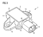
- FIGs 1 and 2 show in different views in each case a perspective view of an electrical device 1 according to the invention, wherein a housing 2 and a connector 3 are shown prior to assembly.
- the electrical device 1 is shown after the assembly of the housing 2 and the connector 3.
- An electrical appliance 1 assembled from the two main components does not differ externally from a conventional electrical appliance of the prior art.
- FIGS. 1 to 3 As will be apparent from the following description, only needs a first connection element 4 of the connector 3 for connection to the housing 2 to be formed in a predetermined manner, while in particular the shape and the dimensions of a chamber 5 (also referred to as a contact cup) can be designed freely in order to be able to be connected to a corresponding contact plug (not shown in the figures).
- a chamber 5 also referred to as a contact cup
- the chamber 5 has a substantially rectangular cross-section with rounded corners.
- outer ends 22 protrude a first contact portion 20 of the connector 3.
- the first contact portions 20 are formed for example as contact pins, via which an electrical contact to the contact plug can be produced.
- a latching element 6 is provided on an outer side of the chamber 5.
- the locking element 6 is merely optional and can also be formed in other ways and elsewhere on the connector 3. The presence and the configuration of the latching element 6 depend essentially on the configuration of the contact plug.
- the first and the second connection element 4, 15 are formed by way of example cylindrical.
- the base of the cylinder 16 is chosen to be circular, although other base surfaces are conceivable.
- the second connection element 15 of the housing 2 extends from a side wall of a housing base body 11 of the housing 2.
- the housing base body 11 has a substantially rectangular shape in plan view. Inside the housing main body, an electronic circuit (not shown) is arranged.
- the electronic circuit may include, for example, components for detecting acceleration and / or pressure and / or structure-borne noise and / or inertia, and the like.
- the design and implementation of the electronic circuit is of secondary importance for the present invention, so that a detailed description is omitted below.
- From two opposite side walls of the housing body 6 each flange-shaped fasteners extend 13, in each of which a bore 14 for fastening the housing to a support surface, for example a body component, is provided.
- the arranged inside the housing base 11 electronic circuit is protected by a closure plate 12 which fits tightly on all side walls of the housing base 11 from external environmental influences.
- External ends 24 of second contact sections 23 protrude from the housing base body 11 within the second connection element 15 of the housing 2 designed as a cylinder 16.
- the outer ends 24 of the second contact sections 23 are designed as blade contacts.
- the number and arrangement of the blade contacts corresponds to this with inner ends 21 of the first contact portions 20 of the connector 3, which extend out of a bottom 8 of the first connection element 4 out (see. Fig. 2 ).
- the inner ends 21 of the first contact portions 20 of the connector 3 are formed flat, so that they can be easily connected to the blade contacts 24 when the connector 3 and the housing 2 are joined together.
- the axes of the inner ends 21 and the outer ends 22 of the respective first contact portions 20 need not necessarily be in one axis. Rather, the first contact portions 20 of the connector may be bent one or more times to allow a contact with the contact plug.
- first and the second connection element 4, 15 each have a hollow cylinder, wherein in the interconnected state, an outer edge 9 of the cylinder 7 of the first connection element 4 of the connector 3 and an inner edge 18 of the cylinder 16 of the housing 2 tight form-fitting and / or non-positively and / or cohesively border each other.
- the cylinder of the first connection element could also the connector 3 may be formed larger than the cylinder of the second connection element of the housing 2, so that in the interconnected state, an outer edge of the cylinder 16 of the second connection element of the housing 2 and an inner edge of the cylinder 7 of the connector 3 tight positive and / or non-positive and / or materially adjacent to one another.
- the inner and outer edges of the cylinder may be formed smooth or profiled.
- the outer edge 9 has a bead and two projections 10.
- a seal 25 which is annular in the exemplary embodiment is arranged between a bottom 17 of the second connection element 15 and the first connection element 4. to hermetically seal the interior space formed between the first and second connection elements 4, 15.
- 15 shows Fig. 4 Furthermore, the production of the electrical contact between the outer end 24 of the second contact portion 23 and the inner end 21 of the first contact portion 20.
- the outer end 22 of the first contact portion 20 projects into the chamber 5 of the connector 3 inside.
- the axes of the inner and outer ends 21, 22 are each arranged in a same axis.
- Fig. 5 shows a further variant of a connector 2 connected to the housing 3, wherein the inner edge 18 of the second connection element 15 and the outer edge 9 of the first connection element 4 are straight.
- the housing 2 and the connector 3 can be connected to each other with less effort.
- the insolubility of the housing 2 and the connector 3 is realized by a welded connection, this being indicated by the reference numeral 19. The welding can be carried out, for example, using a laser.
- the invention provides a bipartition of housing and connector before.
- the area marked A an embodiment of the housing 2 and of the connector 3 according to rules specified by the manufacturer of the electrical device.
- the section marked B of the connector 3 there is complete freedom of design according to the requirements of the customers of the electrical device to allow the connection to customer-specific contact plug, but this does not affect the design and manufacture of the housing 2.
- the connector 3 is accordingly designed as an adapter, which allows a simple and inexpensive way the connection of a specific contact plug with the housing of the electrical device.
Landscapes
- Connector Housings Or Holding Contact Members (AREA)
- Details Of Connecting Devices For Male And Female Coupling (AREA)
Priority Applications (1)
| Application Number | Priority Date | Filing Date | Title |
|---|---|---|---|
| EP08464002A EP2001092A1 (fr) | 2008-02-11 | 2008-02-11 | Appareil électrique pour un véhicule automobile, en particulier capteur |
Applications Claiming Priority (1)
| Application Number | Priority Date | Filing Date | Title |
|---|---|---|---|
| EP08464002A EP2001092A1 (fr) | 2008-02-11 | 2008-02-11 | Appareil électrique pour un véhicule automobile, en particulier capteur |
Publications (1)
| Publication Number | Publication Date |
|---|---|
| EP2001092A1 true EP2001092A1 (fr) | 2008-12-10 |
Family
ID=39471890
Family Applications (1)
| Application Number | Title | Priority Date | Filing Date |
|---|---|---|---|
| EP08464002A Withdrawn EP2001092A1 (fr) | 2008-02-11 | 2008-02-11 | Appareil électrique pour un véhicule automobile, en particulier capteur |
Country Status (1)
| Country | Link |
|---|---|
| EP (1) | EP2001092A1 (fr) |
Cited By (4)
| Publication number | Priority date | Publication date | Assignee | Title |
|---|---|---|---|---|
| WO2010130371A1 (fr) * | 2009-05-15 | 2010-11-18 | Brose Fahrzeugteile Gmbh & Co. Kommanditgesellschaft | Élément boîtier, son procédé de production et unité d'entraînement de lève-vitre |
| WO2012089590A1 (fr) * | 2010-12-29 | 2012-07-05 | Robert Bosch Gmbh | Boîtier comprenant un adaptateur de fiche relié à un surmoulage de boîtier par le biais d'une interface standardisée |
| DE102012218012A1 (de) * | 2012-10-02 | 2014-04-03 | Alfmeier Präzision AG Baugruppen und Systemlösungen | Gehäuse mit zwei aus Kunststoff gefertigten Gehäuseteilen |
| EP2672578A3 (fr) * | 2012-06-05 | 2015-01-28 | Tyco Electronics Brasil Ltda | Assemblage de connecteur électrique |
Citations (6)
| Publication number | Priority date | Publication date | Assignee | Title |
|---|---|---|---|---|
| FR2602376A1 (fr) * | 1986-07-29 | 1988-02-05 | Festo Kg | Connecteur electrique, notamment pour bobines d'electro-aimants |
| EP0691533A2 (fr) * | 1994-07-08 | 1996-01-10 | Fujikoki Mfg. Co., Ltd. | Capteur de pression |
| US20010018294A1 (en) * | 2000-02-29 | 2001-08-30 | Yazaki Corporation | Connector |
| US6447342B1 (en) * | 2001-05-10 | 2002-09-10 | Delphi Technologies, Inc. | Pressure sensor connector |
| US20050042929A1 (en) * | 2003-08-21 | 2005-02-24 | Helms-Man Industrial Co., Ltd. | Plug device with a plug adapter |
| EP1528633A2 (fr) * | 2003-10-31 | 2005-05-04 | Denso Corporation | Structure de boitier en résine pour un dispostif de circuit électrique |
-
2008
- 2008-02-11 EP EP08464002A patent/EP2001092A1/fr not_active Withdrawn
Patent Citations (6)
| Publication number | Priority date | Publication date | Assignee | Title |
|---|---|---|---|---|
| FR2602376A1 (fr) * | 1986-07-29 | 1988-02-05 | Festo Kg | Connecteur electrique, notamment pour bobines d'electro-aimants |
| EP0691533A2 (fr) * | 1994-07-08 | 1996-01-10 | Fujikoki Mfg. Co., Ltd. | Capteur de pression |
| US20010018294A1 (en) * | 2000-02-29 | 2001-08-30 | Yazaki Corporation | Connector |
| US6447342B1 (en) * | 2001-05-10 | 2002-09-10 | Delphi Technologies, Inc. | Pressure sensor connector |
| US20050042929A1 (en) * | 2003-08-21 | 2005-02-24 | Helms-Man Industrial Co., Ltd. | Plug device with a plug adapter |
| EP1528633A2 (fr) * | 2003-10-31 | 2005-05-04 | Denso Corporation | Structure de boitier en résine pour un dispostif de circuit électrique |
Cited By (6)
| Publication number | Priority date | Publication date | Assignee | Title |
|---|---|---|---|---|
| WO2010130371A1 (fr) * | 2009-05-15 | 2010-11-18 | Brose Fahrzeugteile Gmbh & Co. Kommanditgesellschaft | Élément boîtier, son procédé de production et unité d'entraînement de lève-vitre |
| CN102414964A (zh) * | 2009-05-15 | 2012-04-11 | 博泽哈尔施塔特汽车零件两合公司 | 壳体件、用于制造壳体件的方法以及窗户升降装置驱动单元 |
| CN102414964B (zh) * | 2009-05-15 | 2014-04-16 | 博泽哈尔施塔特汽车零件两合公司 | 壳体件、用于制造壳体件的方法以及窗户升降装置驱动单元 |
| WO2012089590A1 (fr) * | 2010-12-29 | 2012-07-05 | Robert Bosch Gmbh | Boîtier comprenant un adaptateur de fiche relié à un surmoulage de boîtier par le biais d'une interface standardisée |
| EP2672578A3 (fr) * | 2012-06-05 | 2015-01-28 | Tyco Electronics Brasil Ltda | Assemblage de connecteur électrique |
| DE102012218012A1 (de) * | 2012-10-02 | 2014-04-03 | Alfmeier Präzision AG Baugruppen und Systemlösungen | Gehäuse mit zwei aus Kunststoff gefertigten Gehäuseteilen |
Similar Documents
| Publication | Publication Date | Title |
|---|---|---|
| DE102013206443B4 (de) | System aus einem Gehäuse und einem Stecker für eine automatisierte, maschinelle Kabelbaumdirektmontage, wobei das System zwei Dichtmittel und zwei Verriegelungsmittel zur irreversiblen Verriegelung umfasst und zugehöriges Herstellungsverfahren | |
| DE102008044349B4 (de) | Direktsteckverbinder und Verfahren zum Herstellen eines Direktsteckverbinders | |
| EP3613110B1 (fr) | Assemblage d'une pièce de connecteur à fiches avec insert de contact et élément de mise à la terre | |
| DE112009000175T5 (de) | Leiterplattengehäuse mit elektrischem Steckverbinder und damit vorgesehener elektronischer Baugruppe | |
| EP1972039B1 (fr) | Adapteur de connexion pour capteurs ou actionneurs | |
| WO2020007555A1 (fr) | Élément de liaison à enfichage pour un véhicule à moteur et procédé pour la fabrication d'un tel élément de liaison à enfichage | |
| EP2025213A1 (fr) | Module de détection comprenant un logement qui peut être monté sur une paroi | |
| DE102010017361A1 (de) | Anbausteckverbinder | |
| DE102004063814A1 (de) | Adapter zur Verwendung mit einem elektronischen Kleinstantrieb | |
| WO2020089010A1 (fr) | Couvercle de carter conçu pour un moteur électrique, moteur électrique et procédé de montage | |
| DE102014104275A1 (de) | Kontaktierungsvorrichtung, Kontaktbolzen zur Verwendung in einer solchen und mit diesen versehene Elektronikbox | |
| DE102013221239B4 (de) | Steuerungseinrichtung | |
| DE102011085128A1 (de) | Vorrichtung zur Bestimmung und/oder Überwachung mindestens einer Prozessgröße | |
| EP2622950B1 (fr) | Appareil de commande | |
| DE102017218709A1 (de) | Einsteckteil für einen Steckplatz in einer teilbaren Kabeldurchführung | |
| WO2013178212A2 (fr) | Support pour composant de véhicule à moteur et procédé de fabrication dudit support | |
| EP3930112A1 (fr) | Connecteur enfichable électrique et procédé de montage d'un connecteur enfichable électrique | |
| EP3642908A1 (fr) | Dispositif de signalisation et connecteur | |
| DE102018207398A1 (de) | Anschlussteil | |
| EP2648285B1 (fr) | Connecteur enfichable destiné à être monté dans une ouverture de boîtier | |
| DE102009023292B4 (de) | Elektrischer Verbinder mit Kontaktbrücke und Verfahren zum Montieren der Kontaktbrücke | |
| EP4213314B1 (fr) | Elément de connexion et composant électronique à multiples prises pour technologie à deux fils | |
| DE102012218901A1 (de) | Sensorvorrichtung mit Positioniereinrichtung | |
| DE102004055432A1 (de) | Gehäuseanordnung und Adapter | |
| WO2018149543A1 (fr) | Dispositif pour assurer le montage d'un composant à son emplacement d'installation prévu |
Legal Events
| Date | Code | Title | Description |
|---|---|---|---|
| PUAI | Public reference made under article 153(3) epc to a published international application that has entered the european phase |
Free format text: ORIGINAL CODE: 0009012 |
|
| AK | Designated contracting states |
Kind code of ref document: A1 Designated state(s): AT BE BG CH CY CZ DE DK EE ES FI FR GB GR HR HU IE IS IT LI LT LU LV MC MT NL NO PL PT RO SE SI SK TR |
|
| AX | Request for extension of the european patent |
Extension state: AL BA MK RS |
|
| AKX | Designation fees paid | ||
| REG | Reference to a national code |
Ref country code: DE Ref legal event code: 8566 |
|
| STAA | Information on the status of an ep patent application or granted ep patent |
Free format text: STATUS: THE APPLICATION IS DEEMED TO BE WITHDRAWN |
|
| 18D | Application deemed to be withdrawn |
Effective date: 20090611 |