EP2001122B1 - Elektromotorsteuerung - Google Patents
Elektromotorsteuerung Download PDFInfo
- Publication number
- EP2001122B1 EP2001122B1 EP08010125.6A EP08010125A EP2001122B1 EP 2001122 B1 EP2001122 B1 EP 2001122B1 EP 08010125 A EP08010125 A EP 08010125A EP 2001122 B1 EP2001122 B1 EP 2001122B1
- Authority
- EP
- European Patent Office
- Prior art keywords
- magnetic flux
- instruction
- excitation current
- current
- electric motor
- Prior art date
- Legal status (The legal status is an assumption and is not a legal conclusion. Google has not performed a legal analysis and makes no representation as to the accuracy of the status listed.)
- Active
Links
Images


Classifications
-
- H—ELECTRICITY
- H02—GENERATION; CONVERSION OR DISTRIBUTION OF ELECTRIC POWER
- H02P—CONTROL OR REGULATION OF ELECTRIC MOTORS, ELECTRIC GENERATORS OR DYNAMO-ELECTRIC CONVERTERS; CONTROLLING TRANSFORMERS, REACTORS OR CHOKE COILS
- H02P21/00—Arrangements or methods for the control of electric machines by vector control, e.g. by control of field orientation
- H02P21/0003—Control strategies in general, e.g. linear type, e.g. P, PI, PID, using robust control
-
- H—ELECTRICITY
- H02—GENERATION; CONVERSION OR DISTRIBUTION OF ELECTRIC POWER
- H02P—CONTROL OR REGULATION OF ELECTRIC MOTORS, ELECTRIC GENERATORS OR DYNAMO-ELECTRIC CONVERTERS; CONTROLLING TRANSFORMERS, REACTORS OR CHOKE COILS
- H02P21/00—Arrangements or methods for the control of electric machines by vector control, e.g. by control of field orientation
- H02P21/06—Rotor flux based control involving the use of rotor position or rotor speed sensors
- H02P21/08—Indirect field-oriented control; Rotor flux feed-forward control
-
- H—ELECTRICITY
- H02—GENERATION; CONVERSION OR DISTRIBUTION OF ELECTRIC POWER
- H02P—CONTROL OR REGULATION OF ELECTRIC MOTORS, ELECTRIC GENERATORS OR DYNAMO-ELECTRIC CONVERTERS; CONTROLLING TRANSFORMERS, REACTORS OR CHOKE COILS
- H02P21/00—Arrangements or methods for the control of electric machines by vector control, e.g. by control of field orientation
- H02P21/22—Current control, e.g. using a current control loop
Definitions
- the present invention relates to an electric motor control device for vector control of an induction motor, more particularly relates to an electric motor control device able to speed the rise of magnetic flux and issue an excitation current instruction preventing overshoot of magnetic flux.
- An induction motor runs a primary current through a stator to generate a rotating magnetic field and has the magnetic flux caused by the rotating magnetic field cut across by a rotor so as to induce voltage at the rotor and cause the flow of a secondary current. It uses the interaction between this secondary current and the magnetic flux to generate torque.
- vector control dividing the primary current flowing through the stator into an excitation current of the magnetic flux direction and a secondary current, that is, a torque current, has been used as the control of the induction motor.
- the torque generated is proportional to the product of magnetic flux generated by the excitation current and torque current.
- FIG. 9 is a view explaining vector control of a conventional induction motor.
- a torque instruction instructing the torque of the induction motor is input to a current controller 5 and is input to the magnetic flux instruction processor 4 for output of a magnetic flux instruction.
- the magnetic flux instruction is processed considering the rotational speed detected by a speed sensor 71 of an induction motor 7 in the magnetic flux instruction processor 4.
- the magnetic flux instruction is input in the current controller 5 in the same way as the torque instruction.
- the torque instruction is input to a torque current processor 53 of the current controller 5.
- the torque current processor 53 processes the torque (q-phase) current instruction.
- the difference between the output torque current instruction and the torque actual current fed back from the voltage conversion device 6 is input to a torque current controller 54.
- the torque current controller 54 processes and outputs a d-phase voltage instruction to be input to a dq-uvw converter 56 in accordance with the difference of the input torque current.
- the excitation instruction is input to an excitation current processor 51 of the current controller 5.
- the excitation current processor 51 outputs an excitation (d-phase) current instruction.
- the difference between the output excitation current instruction and the excitation actual current fed back from the voltage conversion device 6 is input to an excitation current controller 52.
- the excitation current controller 52 processes and outputs the q-phase voltage instruction to be input to the dq-uvw converter 56 in accordance with the difference of the input excitation current.
- the dq-uvw converter 56 converts the input d-phase voltage instruction and q-phase voltage instruction to a u-phase voltage instruction, v-phase voltage instruction, and w-phase voltage instruction.
- the u-phase voltage instruction, v-phase voltage instruction, and w-phase voltage instruction are input to the voltage conversion device 6 as output of the current controller 5.
- the u-phase voltage instruction, v-phase voltage instruction, and w-phase voltage instruction input to the voltage conversion device 6 are converted by the voltage conversion device 6 to the actual currents of the uvw phases supplied to induction motor 7.
- the induction motor 7 is driven by the actual currents of the uvw phases.
- the induction motor 7 outputs the torque instructed by the torque instruction and makes the shaft 8 rotate.
- the actual currents of the uvw phases output from the voltage conversion device 6 are fed back to the current controller 5 where the uvw-dq converter 55 of the current controller 5 converts them to the torque (d-phase) real current and excitation (q-phase) real current which are used as the torque current feedback and excitation current feedback. Further, the speed sensor 71 of the induction motor 7 feeds back the rotational speed of the induction motor 7 to the magnetic flux instruction processor 4.
- the magnetic flux generated rises by a time constant determined from a circuit constant with respect to the excitation current, so until the magnetic flux is established, it becomes delayed as compared with the excitation current.
- Document EP 0 310 050 A2 discloses a slip frequency type vector control apparatus for an induction machine.
- the apparatus is provided with first and second feedback circuits for correcting respective magnetization current command and torque current command supplied feed-forwardly so as to eliminate the influence of a change in temperature of the induction machine secondary resistance and realize a correct vector control.
- the present invention was made in consideration of the above problem and has as its object the provision of an electric motor control device using a value found from a function of a difference of a magnetic flux instruction value and a magnetic flux estimation value or a function of the time t from the time of rise of the magnetic flux as a boost coefficient to speed the rise of the magnetic flux and prevent overshoot.
- the electric motor control device of the present invention is an electric motor control device controlling an excitation current based on a magnetic flux instruction value and controlling a torque current based on a torque instruction value, comprising a coefficient processing means for processing a coefficient found as a function of a difference of the magnetic flux instruction value and a magnetic flux estimation value or a coefficient found as a function of a time from a start of rise of the magnetic flux and an excitation current processing means for processing an excitation current instruction value based on an excitation current value corresponding to the magnetic flux instruction value and a coefficient processed by the coefficient processing means, wherein the processed excitation current instruction value is used to control the excitation current from the start of rise of the magnetic flux to when the magnetic flux reaches the magnetic flux instruction value.
- the device preferably comprises a power converter feeding drive power to an electric motor based on a torque current and excitation current, wherein the excitation current processed by the excitation current processing means is in a range where the size of the vector sum of the processed excitation current and the torque current does not exceed a maximum allowable current value of the power converter.
- the excitation current processing means preferably processes the excitation current instruction value when switching a control mode of an electric motor between a speed control mode and a position control mode.
- the excitation current processing means preferably processes the excitation current instruction value when switching the electric motor from a non-excitation state to an excitation state.
- the excitation current processing means preferably processes the excitation current instruction value when a speed instruction value for an electric motor is changed.
- the excitation current processing means preferably processes the excitation current instruction value when a magnetic flux instruction value for the electric motor is changed.
- the electric motor control device preferably uses the value found from a function of the difference between the magnetic flux instruction value and the magnetic flux estimation value or a function of the time t from the time of rise of the magnetic flux as a boost coefficient, so can speed the rise of the magnetic flux and prevent overshoot of the magnetic flux, so there is no longer any delay in the time by which the magnetic flux converges.
- the magnetic flux estimation value is fed back to process the boost coefficient, so it is possible to give an excitation current instruction in accordance with the state of the magnetic flux.
- the boost coefficient is processed in accordance with a time constant found from a circuit constant of the electric motor, so it is possible to give an excitation current instruction without estimating the state of the magnetic flux.
- the magnetic flux ⁇ generated in an induction motor due to an excitation current i d is not in a proportional relationship to the excitation current i d .
- M the mutual inductance between the stator winding and rotor winding
- R 2 the secondary inductance
- L 2 the secondary inductance
- t the time
- FIG. 1 is a view showing the difference between the case of using a boost coefficient K according to the present invention and the conventional case for explaining the action and effect of the present invention. Note that FIG. 1 is a view for explaining the action and effect of the present invention by one example and does not limit the present invention. The present invention is defined by only the claims.
- the left side explains the conventional case, while the right side shows the case of the present invention.
- the magnetic flux estimation value is fed back to process the boost coefficient, so it is possible to give an excitation current instruction corresponding to the state of the magnetic flux.
- the boost coefficient is processed in accordance with the time constant found from the circuit constant of the electric motor, so it is possible to give an excitation current instruction without estimating the state of the magnetic flux.
- FIG. 2 is a view explaining the boost coefficient K found from a function f(x) of the difference x of the magnetic fluxes in a first embodiment of the present invention.
- the current controller 5 shows only the necessary configuration for processing a boost coefficient K for the excitation current instruction.
- the configurations relating to the torque current control, dq-uvw conversion and its reverse conversion, etc. are omitted. Note that to facilitate understanding, parts of the configuration similar to those in FIG. 9 explaining general vector control are assigned similar notations.
- the excitation current processor 51 calculates the excitation current corresponding to the magnetic flux instruction.
- the calculated excitation current is multiplied with the boost coefficient K to obtain the excitation current instruction.
- the boost coefficient K is determined based on the difference x obtained by subtracting the magnetic flux estimation value processed by the magnetic flux processor 57 based on the excitation current feedback from the voltage conversion device 6 from the magnetic flux instruction input from the magnetic flux instruction processor 4.
- the excitation current controller 52 is controlled by the difference obtained by subtracting the excitation current feedback from the voltage conversion device 6 from the excitation current instruction multiplied with this boost coefficient K, processes the excitation voltage instruction, and outputs it through a dq-uvw converter (not shown) to the voltage conversion device 6. Note that the excitation current feedback from the output of the voltage conversion device 6 corresponds to the output from the uvw-dq converter 55 of FIG. 9 , that is, the excitation (d-phase) actual current.
- G is a constant value
- FIG. 3(a) is a view for explaining the current instruction in the case of acceleration by the maximum allowable current at the time of the rise of the magnetic flux (interval 1)
- FIG. 3(b) is a view for explaining the current instruction after the rise of the magnetic flux (interval 2).
- the torque current instruction when rising at the maximum allowable current at the start of the interval 1, the torque current instruction is 100%, while the excitation current instruction becomes a value of 100% or more. In this case, it is possible to increase the excitation current instruction (shown by + ⁇ ) until the primary current instruction obtained by vector addition of the torque current instruction and excitation current instruction becomes a maximum allowable current of the voltage conversion device.
- FIG. 3(b) shows the relationship of the torque current instruction and the excitation current instruction at the interval 2 when the rise of the magnetic flux is completed. As clear from the figure, both the torque current instruction and the excitation current instruction become values of 100%. The primary current instruction obtained by adding the torque current instruction and the excitation current instruction becomes smaller than the maximum allowable current.
- FIG. 4 is a view showing the boost coefficient determined from the function g(t) of the time t from the time of rise of the magnetic flux of a second embodiment of the present invention.
- FIG. 4 in the same way as FIG. 2 , only the configuration necessary for processing the function g(t) is shown. The rest of the parts are omitted. Note that to facilitate understanding, configurations similar to those in FIG. 9 explaining general vector control are assigned similar notations.
- the excitation current processor 51 calculates the excitation current corresponding to the magnetic flux instruction.
- the calculated excitation current is multiplied with the boost coefficient K to become the excitation current instruction.
- the boost coefficient K is determined based on the function g(t) of the time t from the time of rise of the magnetic flux.
- the difference obtained by subtracting the excitation current feedback from the voltage conversion device 6 from the excitation current instruction multiplied with the boost coefficient K is input to the current controller 52 to calculate the excitation voltage instruction which is output through the dq-uvw converter (not shown) to the voltage conversion device 6.
- the excitation current feedback from the voltage conversion device 6 corresponds to the output of the uvw-dq converter 55 of FIG. 9 , that is, the excitation (d-phase) actual current.
- the boost coefficient K is processed as a function g(t) of the time t from the rise of the magnetic flux, but g(t) is a function which outputs a large excitation current so as to output a maximum allowable current from the voltage conversion device 6 from the rise of the magnetic flux to a predetermined time t1 and which outputs an exponentially falling current as a function of the time t after a predetermined time t1 passes.
- the boost coefficient is switched at the time t1 when the magnetic flux is at a lower A lower than the magnetic flux instruction value ⁇ *.
- f(x) and g(t) can be realized not only by calculation of values as functions as explained above, but also by preparing a table and extracting values corresponding to the difference x or time from the table to obtain the values of f(x) and g(t).
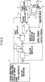
- FIG. 5 is a view explaining the control of the induction motor in the case of switching from the speed control mode where response is not required to position control mode where response is required.
- the induction motor 7 being controlled is provided with a speed sensor 71 detecting the speed of the induction motor 7 and a position sensor 81 detecting the rotational position of the shaft 8 of the induction motor 7.
- the control instruction unit 1 for outputting an instruction value for controlling the induction motor 7 outputs a control mode signal for switching between the speed control mode and the position control mode and outputs a speed instruction and position instruction.
- control instruction unit 1 When switching from speed control where the response of the torque output is not required to position control where the response of the torque output is required, the control instruction unit 1 outputs the position control mode, and the switching means 11 enables position control and strengthens the magnetic flux to secure the response of the torque.
- the position difference obtained by subtracting the position feedback from the position sensor 81 from the position instruction output from the control instruction unit 1 is input to the position controller 2.
- the position controller 2 outputs a speed instruction corresponding to the input position difference.
- the speed difference obtained by subtracting the speed feedback obtained from the speed sensor 71 from the output speed instruction is input to the speed controller 3.
- the speed controller 3 outputs a torque instruction based on the input speed difference.
- the torque instruction is input to the current controller 5.
- the magnetic flux instruction processed from the torque instruction by the magnetic flux instruction processor 4 to strengthen the magnetic flux is input to the current controller 5.
- the current controller 5 outputs a primary current instruction to the voltage conversion device 6.
- the output of the voltage conversion device 6 is used to control the drive of the induction motor.
- the current controller 5 of FIG. 5 employs a configuration for using a boost coefficient from the function f(x) of the difference x between a magnetic flux instruction and a magnetic flux estimation value ( FIG. 2 ) or a configuration using a boost coefficient determined based on a function g(t) of the time t from the time of rise of the magnetic flux ( FIG. 4 ).
- the excitation current instruction is multiplied to the boost coefficient calculated by either of these.
- a boost coefficient processor 58 and a magnetic flux processor 57 are provided. Further, the function f(x) is found and the boost coefficient K is determined based on the difference x between the magnetic flux instruction input from the magnetic flux instruction processor 4 to the current controller 5 and the magnetic flux estimation value processed and output by the magnetic flux processor 57 to which the excitation current feedback is input. The excitation current calculated by the excitation current processor 51 is multiplied with the boost coefficient K and becomes the excitation current instruction.
- a boost coefficient processor 58 having the function g(t) is provided.
- the time t from the time of rise of the magnetic flux is input to the boost coefficient processor 58 and the value of the function g(t) is used to determine the boost coefficient K.
- the excitation current corresponding to the magnetic flux instruction is multiplied with the boost coefficient K to find the excitation current instruction.
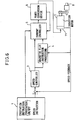
- FIG. 6 is a view for explaining the excitation current control of the induction motor at the time of switching from the non-excitation state to the excitation state.
- the induction motor 7 to be controlled is for driving rotation of the shaft 8 and is provided with a speed sensor 71 for detecting the speed of the induction motor 7.
- the control instruction unit 1 for outputting an instruction value for control of the induction motor 7 is configured to output a drive instruction and speed instruction.
- control instruction unit 1 When switching from the non-excitation state where no magnetic flux is generated to the excitation state, the control instruction unit 1 outputs an excitation instruction for turning on the excitation and outputs a speed instruction.
- the speed feedback obtained by the speed sensor 71 is subtracted from the output speed instruction to calculate the speed difference.
- This speed difference is input to the speed controller 3.
- the speed controller 3 outputs a torque instruction based on the input speed difference.
- the torque instruction is input to the current controller 5, Furthermore, the magnetic flux instruction processed from the torque instruction by the magnetic flux instruction processor 4 to generate the predetermined magnetic flux is input to the current controller 5.
- FIG. 7 is a view showing the excitation current control of an induction motor when the speed instruction is changed.
- FIG. 7 differs from FIG. 6 in that the control instruction unit 1 is not one outputting a control instruction for turning the excitation on/off, but has a speed instruction change detector 9 detecting the change of the speed instruction. The rest of the configuration is the same.
- control instruction unit 1 changes the speed instruction
- the speed feedback obtained by the speed sensor 71 of the induction motor 7 is subtracted from the changed speed instruction to calculate the speed difference.
- This speed difference is input to the speed controller 3.
- the speed controller 3 outputs the torque instruction based on the input speed difference.
- the magnetic flux instruction processor 4 outputs a magnetic flux instruction for generating the changed magnetic flux. This magnetic flux instruction is input to the current controller 5.
- the speed instruction change detector 9 detects each time the speed instruction is changed and inputs the speed instruction change detection signal to the current controller 5. Due to the input of the speed instruction change detection signal, the current controller 5 starts the magnetic flux raising processing multiplying the boost coefficient according to the present embodiment with the excitation current to strengthen the magnetic flux and generate a torque and quickly end the acceleration/deceleration until reaching the changed speed.
- FIG. 8 is a view showing the excitation current control when the processing or operation where instantaneous response of the torque is required is known in advance.
- the control device shown in FIG. 8 is configured so that the control instruction unit 1 outputs the magnetic flux boost signal to the current controller 5. Compared with FIG. 6 , in FIG. 6 , the control instruction unit 1 outputs a control instruction turning the excitation on/off to the current controller 5, while in FIG. 8 , it outputs a magnetic flux boost signal to the current controller 5. The rest of the configuration is the same.
- control instruction unit 1 When the processing or operation where instantaneous response of the torque is required is known in advance, at that time, the control instruction unit 1 outputs a magnetic flux boost signal and inputs it to the current controller 5.
- the current controller 5 starts the processing for raising the magnetic flux according to the present embodiment which multiplies the boost coefficient K with the excitation current upon the input of the magnetic flux boost signal so as to strengthen the magnetic flux and generate a torque.
Landscapes
- Engineering & Computer Science (AREA)
- Power Engineering (AREA)
- Control Of Ac Motors In General (AREA)
Claims (6)
- Elektromotorsteuervorrichtung (5) zum Steuern eines Erregungsstroms auf der Grundlage eines Magnetflussanweisungswerts und zum Steuern eines Drehmomentstroms auf der Grundlage eines Drehmomentanweisungswerts, umfassend:eine Koeffizientenverarbeitungseinrichtung (56), die konfiguriert ist, um einen Koeffizienten, der als eine Funktion f(x) einer Differenz x des Magnetflussanweisungswerts und eines Magnetflussschätzwerts ermittelt wird, oder einen Koeffizienten zu verarbeiten, der als eine Funktion g(t) einer Zeit t von einem Beginn (t = 0) des Anstiegs eines magnetischen Flusses ermittelt wurde; undeine Erregungsstromverarbeitungseinrichtung (51), die konfiguriert ist, um einen Erregungsstromanweisungswert auf der Grundlage eines Erregungsstromwerts, der dem Magnetflussanweisungswert entspricht, und des durch die Koeffizientenverarbeitungseinrichtung verarbeiteten Koeffizienten zu verarbeiten, wobei der Koeffizient in einem vorbestimmten Zeitintervall von dem Beginn des Anstiegs des magnetischen Flusses größer als 1 ist und danach auf 1 verringert wird,wobei der verarbeitete Erregungsstromanweisungswert verwendet wird, um den Erregungsstrom von dem Beginn des Anstiegs des magnetischen Flusses bis zu dem Zeitpunkt zu steuern, zu dem der magnetische Fluss den Magnetflussanweisungswert erreicht,dadurch gekennzeichnet, dassdie Funktion f(x) als die nachfolgende Gleichung definiert wird:

 Imax: maximal zulässiger Strom,i2*: Drehmomentstromanweisung,id*: Erregungsstromanweisung,G: ein konstanter Wert,t1: eine vorbestimmte Zeit,T: ein vorbestimmtes Intervall,R2: Gegenwert des sekundären Widerstands innerhalb einer einzelnen Phase, undL2: die sekundäre Induktivität.
 - Elektromotorsteuervorrichtung gemäß Anspruch 1, weiterhin umfassend einen Stromwandler (6), der konfiguriert ist, um einem Elektromotor (7) einen Treiberstrom auf der Grundlage eines Drehmomentstroms und eines Erregungsstroms zuzuführen,
wobei der Erregungsstrom, der durch die Erregungsstromverarbeitungseinrichtung verarbeitet ist, sich in einem Bereich befindet, in dem die Größe der Vektorsumme des verarbeiteten Erregungsstroms und des Drehmomentstroms einen maximal zulässigen Stromwert des Stromwandlers nicht überschreitet. - Elektromotorsteuervorrichtung gemäß Anspruch 1 oder 2, wobei die Erregungsstromverarbeitungseinrichtung weiterhin konfiguriert ist, um den Erregungsstromanweisungswert zu verarbeiten, wenn ein Umschalten eines Steuermodus eines Elektromotors zwischen einem Geschwindigkeitssteuermodus und einem Positionssteuermodus stattfindet.
- Elektromotorsteuervorrichtung gemäß Anspruch 1 oder 2, wobei die Erregungsstromverarbeitungseinrichtung weiterhin konfiguriert ist, um den Erregungsstromanweisungswert zu verarbeiten, wenn ein Umschalten eines Elektromotors von einem Nicht-Erregungszustand in einen Erregungszustand stattfindet.
- Elektromotorsteuervorrichtung gemäß Anspruch 1 oder 2, wobei die Erregungsstromverarbeitungseinrichtung weiterhin konfiguriert ist, um den Erregungsstromanweisungswert zu verarbeiten, wenn ein Geschwindigkeitsanweisungswert für den Elektromotor verändert wird.
- Elektromotorsteuervorrichtung gemäß Anspruch 1 oder 2, wobei die Erregungsstromverarbeitungseinrichtung weiterhin konfiguriert ist, um den Erregungsstromanweisungswert zu verarbeiten, wenn ein Magnetflussanweisungswert für den Elektromotor verändert wird.
Applications Claiming Priority (1)
| Application Number | Priority Date | Filing Date | Title |
|---|---|---|---|
| JP2007149636A JP4235233B2 (ja) | 2007-06-05 | 2007-06-05 | 電動機制御装置 |
Publications (3)
| Publication Number | Publication Date |
|---|---|
| EP2001122A2 EP2001122A2 (de) | 2008-12-10 |
| EP2001122A3 EP2001122A3 (de) | 2015-08-05 |
| EP2001122B1 true EP2001122B1 (de) | 2017-05-31 |
Family
ID=39790922
Family Applications (1)
| Application Number | Title | Priority Date | Filing Date |
|---|---|---|---|
| EP08010125.6A Active EP2001122B1 (de) | 2007-06-05 | 2008-06-03 | Elektromotorsteuerung |
Country Status (4)
| Country | Link |
|---|---|
| US (1) | US7863853B2 (de) |
| EP (1) | EP2001122B1 (de) |
| JP (1) | JP4235233B2 (de) |
| CN (1) | CN101320955B (de) |
Families Citing this family (14)
| Publication number | Priority date | Publication date | Assignee | Title |
|---|---|---|---|---|
| WO2013057780A1 (ja) * | 2011-10-17 | 2013-04-25 | 三菱電機株式会社 | モータ制御装置 |
| JP6089775B2 (ja) * | 2013-02-26 | 2017-03-08 | 日産自動車株式会社 | モータ制御装置 |
| JP2015130739A (ja) * | 2014-01-07 | 2015-07-16 | ファナック株式会社 | 磁束制御適用の有無を切り換え可能なモータ制御装置 |
| US9520820B2 (en) * | 2014-12-23 | 2016-12-13 | Deere & Company | Method and apparatus for auto-tuning an electric machine current regulator |
| JP6088604B1 (ja) | 2015-08-27 | 2017-03-01 | ファナック株式会社 | 磁束制御部を有する電動機制御装置、ならびに機械学習装置およびその方法 |
| CN106814703A (zh) * | 2015-11-27 | 2017-06-09 | 沈阳高精数控智能技术股份有限公司 | 一种交流伺服驱动单元控制模式快速平滑切换的方法 |
| JP6625957B2 (ja) * | 2016-10-31 | 2019-12-25 | ファナック株式会社 | 工作機械の数値制御装置 |
| JP6635059B2 (ja) * | 2017-01-24 | 2020-01-22 | 株式会社デンソー | 交流電動機の制御装置 |
| JP6334017B1 (ja) * | 2017-01-25 | 2018-05-30 | ファナック株式会社 | 誘導電動機の制御装置 |
| JP6629814B2 (ja) | 2017-10-19 | 2020-01-15 | ファナック株式会社 | モータ制御装置 |
| JP6603285B2 (ja) | 2017-10-19 | 2019-11-06 | ファナック株式会社 | モータ制御装置 |
| CN107659237B (zh) * | 2017-11-09 | 2019-07-19 | 合肥工业大学 | 一种永磁同步电机的无模型无差拍电流预测控制装置及其方法 |
| EP3714540B1 (de) * | 2017-11-20 | 2021-09-15 | 77 Elektronika Müszeripari Kft. | Zentrifuge und steuerverfahren dafür, computerprogramm zur durchführung des verfahrens und speichermedium |
| CN109742990A (zh) * | 2019-01-30 | 2019-05-10 | 深圳市康普斯节能科技股份有限公司 | 一种电机磁链观测方法和系统 |
Family Cites Families (7)
| Publication number | Priority date | Publication date | Assignee | Title |
|---|---|---|---|---|
| JPH0667253B2 (ja) | 1985-02-28 | 1994-08-24 | 株式会社東芝 | 電動機制御装置 |
| US4962339A (en) * | 1987-08-21 | 1990-10-09 | Westinghouse Electric Corp. | Pole-tying current control apparatus |
| DE3850207T2 (de) * | 1987-09-29 | 1995-02-16 | Toshiba Kawasaki Kk | Regelvorrichtung für eine Induktionsmaschine. |
| US5196778A (en) * | 1989-06-23 | 1993-03-23 | Mitsubishi Denki Kabushiki Kaisha | Control apparatus suitable for use in induction motor |
| JP3262253B2 (ja) * | 1995-02-22 | 2002-03-04 | 株式会社日立製作所 | 電気車用駆動制御装置及び制御方法 |
| US6335609B1 (en) * | 2000-05-09 | 2002-01-01 | Ford Global Technologies, Inc. | Method for reducing peak phase current and decreasing staring time for an internal combustion engine having an induction machine |
| JP4245777B2 (ja) * | 2000-05-25 | 2009-04-02 | 三菱電機株式会社 | 誘導電動機の制御装置および制御方法 |
-
2007
- 2007-06-05 JP JP2007149636A patent/JP4235233B2/ja active Active
-
2008
- 2008-06-03 US US12/132,103 patent/US7863853B2/en not_active Expired - Fee Related
- 2008-06-03 EP EP08010125.6A patent/EP2001122B1/de active Active
- 2008-06-04 CN CN2008101099076A patent/CN101320955B/zh active Active
Also Published As
| Publication number | Publication date |
|---|---|
| CN101320955B (zh) | 2012-07-04 |
| EP2001122A2 (de) | 2008-12-10 |
| JP2008306798A (ja) | 2008-12-18 |
| US20080303476A1 (en) | 2008-12-11 |
| JP4235233B2 (ja) | 2009-03-11 |
| US7863853B2 (en) | 2011-01-04 |
| EP2001122A3 (de) | 2015-08-05 |
| CN101320955A (zh) | 2008-12-10 |
Similar Documents
| Publication | Publication Date | Title |
|---|---|---|
| EP2001122B1 (de) | Elektromotorsteuerung | |
| JP5318286B2 (ja) | 交流回転機の制御装置 | |
| EP1944862B1 (de) | Induktiosmotorsteuerung | |
| JP6776066B2 (ja) | インバータ制御装置および電動機駆動システム | |
| KR101738670B1 (ko) | 모터 제어 장치 | |
| EP2642658A2 (de) | Steuerung für einen Elektromotor | |
| EP3883123B1 (de) | Motorsteuerungsvorrichtung | |
| JP3674741B2 (ja) | 永久磁石同期電動機の制御装置 | |
| EP3157162A1 (de) | Motorsteuerungsvorrichtung und verfahren zur korrektur der drehmomentkonstante in solch einer motorsteuerungsvorrichtung | |
| JPWO2013057780A1 (ja) | モータ制御装置 | |
| KR102164956B1 (ko) | 모터 제어 장치 및 방법 | |
| JPH0984400A (ja) | サーボモータの電流制御方法 | |
| JP5994355B2 (ja) | 永久磁石形同期電動機の制御装置 | |
| EP3719991A1 (de) | Verfahren und vorrichtung zur steuerung eines elektromotors | |
| JP4402600B2 (ja) | 同期電動機の駆動システム及び同期電動機の駆動方法 | |
| JP2006238605A (ja) | 電動機の駆動装置 | |
| JP4583257B2 (ja) | 交流回転機の制御装置 | |
| JP4579627B2 (ja) | 回転機の制御装置 | |
| US9438158B2 (en) | Motor control device controlling synchronous motor | |
| CN103166560A (zh) | 电动机的控制装置 | |
| JP5713850B2 (ja) | モータ制御装置 | |
| JP2009284598A (ja) | 交流電動機の制御装置 | |
| WO2014141527A1 (ja) | モータ制御装置 | |
| JP5390970B2 (ja) | モータ制御装置 | |
| CN111095775B (zh) | 同步电动机的控制装置及控制方法 |
Legal Events
| Date | Code | Title | Description |
|---|---|---|---|
| PUAI | Public reference made under article 153(3) epc to a published international application that has entered the european phase |
Free format text: ORIGINAL CODE: 0009012 |
|
| AK | Designated contracting states |
Kind code of ref document: A2 Designated state(s): AT BE BG CH CY CZ DE DK EE ES FI FR GB GR HR HU IE IS IT LI LT LU LV MC MT NL NO PL PT RO SE SI SK TR |
|
| AX | Request for extension of the european patent |
Extension state: AL BA MK RS |
|
| RAP1 | Party data changed (applicant data changed or rights of an application transferred) |
Owner name: FANUC CORPORATION |
|
| PUAL | Search report despatched |
Free format text: ORIGINAL CODE: 0009013 |
|
| AK | Designated contracting states |
Kind code of ref document: A3 Designated state(s): AT BE BG CH CY CZ DE DK EE ES FI FR GB GR HR HU IE IS IT LI LT LU LV MC MT NL NO PL PT RO SE SI SK TR |
|
| AX | Request for extension of the european patent |
Extension state: AL BA MK RS |
|
| RIC1 | Information provided on ipc code assigned before grant |
Ipc: H02P 21/08 20060101ALI20150701BHEP Ipc: G05B 19/19 20060101ALN20150701BHEP Ipc: H02P 21/00 20060101AFI20150701BHEP |
|
| 17P | Request for examination filed |
Effective date: 20151215 |
|
| AKX | Designation fees paid |
Designated state(s): DE |
|
| AXX | Extension fees paid |
Extension state: BA Extension state: RS Extension state: AL Extension state: MK |
|
| 17Q | First examination report despatched |
Effective date: 20160421 |
|
| RIC1 | Information provided on ipc code assigned before grant |
Ipc: H02P 21/08 20160101ALI20161118BHEP Ipc: H02P 21/22 20160101ALI20161118BHEP Ipc: H02P 21/00 20160101AFI20161118BHEP Ipc: G05B 19/19 20060101ALN20161118BHEP |
|
| GRAP | Despatch of communication of intention to grant a patent |
Free format text: ORIGINAL CODE: EPIDOSNIGR1 |
|
| STAA | Information on the status of an ep patent application or granted ep patent |
Free format text: STATUS: GRANT OF PATENT IS INTENDED |
|
| RIC1 | Information provided on ipc code assigned before grant |
Ipc: H02P 21/00 20160101AFI20161213BHEP Ipc: H02P 21/22 20160101ALI20161213BHEP Ipc: H02P 21/08 20160101ALI20161213BHEP Ipc: G05B 19/19 20060101ALN20161213BHEP |
|
| INTG | Intention to grant announced |
Effective date: 20170103 |
|
| RIN1 | Information on inventor provided before grant (corrected) |
Inventor name: TSUTSUMI, TOMOHISA Inventor name: IWASHITA, YASUSUKE Inventor name: NIWA, MASAKAZU Inventor name: AKIYAMA, TAKAHIRO |
|
| GRAS | Grant fee paid |
Free format text: ORIGINAL CODE: EPIDOSNIGR3 |
|
| GRAA | (expected) grant |
Free format text: ORIGINAL CODE: 0009210 |
|
| STAA | Information on the status of an ep patent application or granted ep patent |
Free format text: STATUS: THE PATENT HAS BEEN GRANTED |
|
| AK | Designated contracting states |
Kind code of ref document: B1 Designated state(s): DE |
|
| REG | Reference to a national code |
Ref country code: DE Ref legal event code: R096 Ref document number: 602008050448 Country of ref document: DE |
|
| REG | Reference to a national code |
Ref country code: DE Ref legal event code: R097 Ref document number: 602008050448 Country of ref document: DE |
|
| PLBE | No opposition filed within time limit |
Free format text: ORIGINAL CODE: 0009261 |
|
| STAA | Information on the status of an ep patent application or granted ep patent |
Free format text: STATUS: NO OPPOSITION FILED WITHIN TIME LIMIT |
|
| 26N | No opposition filed |
Effective date: 20180301 |
|
| PGFP | Annual fee paid to national office [announced via postgrant information from national office to epo] |
Ref country code: DE Payment date: 20250520 Year of fee payment: 18 |