EP2002041B1 - Rundstrickmaschine für strumpfwaren oder dergleichen - Google Patents
Rundstrickmaschine für strumpfwaren oder dergleichen Download PDFInfo
- Publication number
- EP2002041B1 EP2002041B1 EP07734204A EP07734204A EP2002041B1 EP 2002041 B1 EP2002041 B1 EP 2002041B1 EP 07734204 A EP07734204 A EP 07734204A EP 07734204 A EP07734204 A EP 07734204A EP 2002041 B1 EP2002041 B1 EP 2002041B1
- Authority
- EP
- European Patent Office
- Prior art keywords
- needle
- needle cylinder
- connecting element
- actuation
- heel
- Prior art date
- Legal status (The legal status is an assumption and is not a legal conclusion. Google has not performed a legal analysis and makes no representation as to the accuracy of the status listed.)
- Active
Links
Images




Classifications
-
- D—TEXTILES; PAPER
- D04—BRAIDING; LACE-MAKING; KNITTING; TRIMMINGS; NON-WOVEN FABRICS
- D04B—KNITTING
- D04B9/00—Circular knitting machines with independently-movable needles
- D04B9/06—Circular knitting machines with independently-movable needles with needle cylinder and dial for ribbed goods
- D04B9/08—Circular knitting machines with independently-movable needles with needle cylinder and dial for ribbed goods for interlock goods
-
- D—TEXTILES; PAPER
- D04—BRAIDING; LACE-MAKING; KNITTING; TRIMMINGS; NON-WOVEN FABRICS
- D04B—KNITTING
- D04B9/00—Circular knitting machines with independently-movable needles
- D04B9/10—Circular knitting machines with independently-movable needles with two needle cylinders for purl work or for Links-Links loop formation
-
- D—TEXTILES; PAPER
- D04—BRAIDING; LACE-MAKING; KNITTING; TRIMMINGS; NON-WOVEN FABRICS
- D04B—KNITTING
- D04B15/00—Details of, or auxiliary devices incorporated in, weft knitting machines, restricted to machines of this kind
-
- D—TEXTILES; PAPER
- D04—BRAIDING; LACE-MAKING; KNITTING; TRIMMINGS; NON-WOVEN FABRICS
- D04B—KNITTING
- D04B15/00—Details of, or auxiliary devices incorporated in, weft knitting machines, restricted to machines of this kind
- D04B15/32—Cam systems or assemblies for operating knitting instruments
-
- D—TEXTILES; PAPER
- D04—BRAIDING; LACE-MAKING; KNITTING; TRIMMINGS; NON-WOVEN FABRICS
- D04B—KNITTING
- D04B15/00—Details of, or auxiliary devices incorporated in, weft knitting machines, restricted to machines of this kind
- D04B15/32—Cam systems or assemblies for operating knitting instruments
- D04B15/325—Cam systems or assemblies for operating knitting instruments in circular knitting machines with two opposed needle cylinders
-
- D—TEXTILES; PAPER
- D04—BRAIDING; LACE-MAKING; KNITTING; TRIMMINGS; NON-WOVEN FABRICS
- D04B—KNITTING
- D04B9/00—Circular knitting machines with independently-movable needles
Definitions
- the present invention relates to a circular knitting machine for hosiery or the like.
- double-cylinder circular knitting machines for hosiery generally comprise a lower needle cylinder which has a vertical axis and an upper needle cylinder which is arranged above and coaxially with respect to the lower needle cylinder, said cylinders being actuatable rigidly with each other with a rotary motion about the common axis.
- a plurality of axial slots are formed on the lateral surface of the lower needle cylinder and on the lateral surface of the upper needle cylinder.
- the axial slots of the upper needle cylinder are aligned with the axial slots of the lower needle cylinder.
- a selector and a slider are generally accommodated in each of the axial slots of the lower needle cylinder, starting from the bottom, while each of the axial slots of the upper needle cylinder accommodates a slider.
- each of the axial slots there is a needle which is provided with two tips or heads, respectively an upper head and a lower head; depending on whether one wishes to provide plain stitches or purl stitches, said needle is moved into the lower needle cylinder so that its knits with its upper tip or into the upper needle cylinder so that its knits with its lower tip.
- the needle Since the needle does not have a heel, it is actuated by means of the slider arranged in the lower needle cylinder or by means of the slider arranged in the upper needle cylinder, depending on whether it has to form plain or purl stitches.
- the sliders currently used in double-cylinder circular knitting machines for hosiery are constituted generally by an elongated laminar body, which has a first longitudinal side designed to rest on the bottom of the axial slot formed on the lateral surface of the lower needle cylinder or on the lateral surface of the upper needle cylinder.
- Said sliders are further provided with two heels, which are mutually spaced along the longitudinal extension of the slider and protrude transversely from a second longitudinal side of the slider which lies opposite the first side.
- These heels are used to cause the movement of the slider along the corresponding axial slot of the lower or upper needle cylinder so as to cause the actuation of the needle associated with said slider in the various types of knitting of the machine or to transfer the needle from one needle cylinder to the other.
- the slider is further provided, on its first longitudinal side, i.e., on its side directed toward the bottom of the axial slot within which it is accommodated, with a hook-shaped tab, which can engage the lower head of the needle or the upper head depending on whether the slider is in the lower needle cylinder or in the upper needle cylinder.
- a plurality of slider actuation cams which define a series of paths with which the heels of the sliders engage when the needle cylinders are actuated with a rotary motion about their axis with respect to said cams.
- the paths defined by the cams are shaped so as to cause the movement of the sliders along the axial slots of the needle cylinders in which they are accommodated and consequently cause the actuation of the needles that are associated therewith.
- cams that define the paths for the heels of the sliders are provided so that they can move along a radial direction with respect to the needle cylinders, so that they can be transferred from an active position, in which they are close to the needle cylinders so that they are engaged by the heels of the sliders, to an inactive position, in which they are spaced from the needle cylinders so as to not interfere with the heels of the sliders, or vice versa, in order to allow to vary the paths for the heels of the sliders and consequently vary the types of knitting that the machine can perform.
- the aim of the present invention is to solve the problems described above by providing a circular knitting machine for hosiery or the like which can operate correctly with a limited number of movable cams or with no movable cams at all.
- an object of the invention is to provide a machine in which the set of actuation cams arranged around the needle cylinder, in the case of a single-cylinder machine, or around the needle cylinders, in the case of a double-cylinder machine, is simplified considerably with respect to known types of machine.
- Another object of the invention is to provide a machine which despite a simplification of the actuation cams arranged around the needle cylinder or cylinders still allows to perform the usual types of knitting that are possible in circular knitting machines for hosiery of the traditional type.
- a circular knitting machine for hosiery or the like which comprises at least one needle cylinder which has a vertical axis and has, on its lateral surface, a plurality of axial slots, each of which accommodates a needle and a needle actuation element; said actuation element being engageable, with one of its ends, with the needle arranged in the same axial slot; said needle or said actuation element being provided with at least one fixed heel, which protrudes radially from the lateral surface of the needle cylinder to engage actuation cams, which are arranged around the lateral surface of the needle cylinder and define paths which can be traced by said fixed heel as a consequence of the actuation of said needle cylinder with a rotary motion about its own axis with respect to said actuation cams, characterized in that said actuation element is provided with a heel which can move on command from an active position, in which it protrudes radially from the corresponding
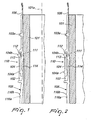
- the machine according to the invention comprises a needle cylinder 101, which has a vertical axis 101a and has, on its lateral surface, a plurality of axial slots 102, each of which accommodates a needle 106 and an actuation element 110 for the needle 106.
- the actuation element 110 comprises at least one connecting element 104 which is provided, on its side directed toward the outside of the needle cylinder 101, with at least one movable heel 104a.
- the connecting element 104 can oscillate on a radial plane of the needle cylinder 101 in order to cause the transfer of the movable heel 104a from an active position, shown in Figure 2 , in which the movable heel 104a protrudes radially from the corresponding axial slot 102 of the needle cylinder 101 in order to engage corresponding connecting element actuation cams 109 which face the lateral surface of the needle cylinder 101 and define paths which can be followed by the movable heel 104a, in the active position, as a consequence of the actuation of the needle cylinder 101 with a rotary motion about its own axis 101a with respect to the connecting element actuation cams 109, to an inactive position, shown in Figure 1 , in which the movable heel 104a is contained in the axial slot 102 of the needle cylinder 101 so
- the actuation element 110 also comprises also comprises a selector 105, which is provided with an elongated laminar body and has a portion 114 which protrudes between the connecting element 104 and the bottom of the axial slot 102 of the needle cylinder 101, in which it is accommodated, preferably in any position which can be assumed by the connecting element 104 during the operation of the machine so that it is always possible to act, by means of the selector 105, on the connecting element 104.
- the selector 105 can oscillate on a radial plane of the needle cylinder 101 to cause the oscillation of the connecting element 104 in the direction of oscillation which produces the transfer of the movable heel 104a of the connecting element 104 from the inactive position to the active position.
- the connecting element 104 has an elongated laminar body and is connected to the longitudinal end of the needle 106 which lies opposite the tip or head of the needle 106.
- the connecting element 104 is pivoted to the needle 106 about a pivoting axis 111, which is perpendicular to the radial plane, i.e., to the plane of arrangement of the connecting element 104 which is inserted in the axial slot 102.
- the connecting element 104 can oscillate about said pivoting axis 111 with respect to the needle 106 in other to produce the transfer of the movable heel 104a from the active position to the inactive position or vice versa.
- the needle 106 has, in an intermediate region of its longitudinal extension, a fixed heel 103a which protrudes radially from the corresponding axial slot 102 of the needle cylinder 101 and can engage needle actuation cams 108 which face the lateral surface of the needle cylinder 101 and define paths which can be followed by the fixed heel 103a as a consequence of the actuation of the needle cylinder 101 with a rotary motion about its own axis 101a with respect to the needle actuation cams 108.
- the connecting element 104 is pivoted directly to the needle 106, but as an alternative it might be pivoted to an intermediate element arranged between the connecting element 104 and the needle 106, which are arranged in a same axial slot 102 of the needle cylinder 101.
- the intermediate element might be connected to the needle 106, preferably with a bilateral connection, so as to transmit to the needle 106 an alternating movement parallel to the axis 101 a of the needle cylinder 101.
- the connecting element 104 would be pivoted to the intermediate element about a pivoting axis which is perpendicular to the radial plane so as to be able to oscillate about said pivoting axis with respect to the intermediate element for the transfer of the movable heel 104a from the active position to the inactive position or vice versa.
- the connecting element 104 is pivoted to the needle 106 or to the intermediate element about the pivoting axis 111, proximate to a longitudinal end thereof, and the movable heel 104a lies proximate to the opposite longitudinal end of the connecting element 104.
- the pivoting between the connecting element 104 and the needle 106 or the intermediate element is constituted preferably by a protrusion 112, which lies on the side of the needle 106 or intermediate element which is directed in the opposite direction with respect to the bottom of the axial slot 102 in which it is accommodated, and by a seat 113 which accommodates, so that it can rotate about the axis 111, the protrusion 112 and is formed in the connecting element 104.
- the connecting element 104 has, at its end connected to the needle 106 or intermediate element, a second heel 104b, which protrudes radially toward the outside of the needle cylinder 101.
- This second heel 104b protrudes constantly from the lateral surface of the needle cylinder 101 and in the specific case can be used as a grip element of the assembly constituted by the needle 106, by the optional intermediate element and by the connecting element 104 in order to replace it during machine maintenance.
- the needle actuation cams 108 and the connecting element actuation cams 109 define paths which can be engaged by the heels 103a of the needles 106 and by the movable heels 104a, in the active position, of the connecting elements 104. These paths are shaped so as to cause the sliding of the needles 106 and of the connecting elements 104 which engage them along the axial slots 102 of the needle cylinder 101 in which they are accommodated, in order to obtain the formation of knitting by the needles 106 or to keep the needless 106 in a non-actuated or "off-work" condition when the needle cylinder 101 is actuated with a rotary motion about its own axis 101a with respect to said cams.
- the needle actuation cams 108 and the connecting element actuation cams 109 at at least one feed or drop of the machine, whose position is indicated by the line A in the figures, comprise: an extraction cam 128, a retraction cam 132 and a knockover cam 129, which are arranged sequentially along a direction of rotation, indicated by the arrow 135, of the needle cylinder 101 about its own axis 101a with respect to the actuation cams 108, 109.
- the extraction cam 128 can always be engaged by the fixed heel 103a to cause the movement of the corresponding needle 106 into an extracted off-work position.
- the retraction cam 132 can be engaged exclusively by the movable heel 104a of the connecting elements 104 in the active position to move the needle 106 to such a level as to engage, with its fixed heel 103a, the knockover cam 129 which moves the needle 106 from the extracted off-work position to the retracted position for forming a new loop of knitting, with lowering of the previously formed loop of knitting
- the machine according to the invention can be actuated with a rotary motion about its own axis along two directions of rotation, and said feed A is adapted to dispense the thread or threads to the needles of the machine in both directions of rotation of the needle cylinder 101 about its own axis 101a with respect to the actuation cams 108, 109.
- an extraction cam 130 for this purpose, at the feed A being considered there are also: an extraction cam 130, a retraction cam 133 and a knockover cam 131, which are arranged sequentially along the opposite direction of rotation, indicated by the arrow 136, of the needle cylinder 101 about its own axis 101a with respect to the actuation cams 108, 109.
- the extraction cam 130 can always be engaged by the fixed heel 103a to cause the movement of the corresponding needle 106 into an extracted off-work position.
- the retraction cam 133 can be engaged exclusively by the movable heel 104a of the connecting elements 104 in the active position to move the needle 106 to such a level as to engage, with its fixed heel 103a, the knockover cam 131 which moves the needle 106 from the extracted off-work position to the retracted position for forming a new loop of knitting, with lowering of the previously formed loop of knitting.
- the needle actuation cams 108 further comprise a central cam 126 and a central complementary cam 127, which are arranged between the knockover cams 129 and 131.
- the retraction cams 132 and 133 are provided monolithically, but they might also be provided as separate cams.
- pressers 162, 163 in the region of the connecting element actuation cams 109 which can act respectively on the connecting elements 104 to cause their oscillation on a radial plane of the needle cylinder 101 and actuate the transfer of the movable heel 104a from the active position to the inactive position.
- pressers are fixed, i.e.; rigidly coupled to the cam box or support, and therefore do not require an actuator for their operation.
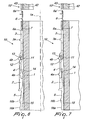
- the machine according to the invention comprises a lower needle cylinder 1, which has a vertical axis 1a, and an upper needle cylinder 42, which is arranged upward and coaxially with respect to the lower needle cylinder 1.
- a plurality of mutually aligned axial slots 2, 43 are formed on the lateral surface of the lower needle cylinder 1 and on the lateral surface of the upper needle cylinder 42.
- An actuation element 10, 10' for a needle 6 is accommodated in each of the axial slots 2, 43 of the lower needle cylinder 1 and of the upper needle cylinder 42, and a needle 6 with a double head or tip is arranged proximate to the mutually facing axial ends of the needle cylinders 1, 42 in one of the needle cylinders 1, 42.
- the actuation element 10 arranged in the lower needle cylinder 1, referenced hereinafter as “lower actuation element”, comprises a slider 3, which is provided, proximate to one of its longitudinal ends, with means for engaging a head of the needle 6.
- the lower actuation element 10 also comprises a connecting element 4, similar to the connecting element 104, which is pivoted to the longitudinal end of the slider 3 which lies opposite the end that can engage the needle 6.
- the slider 3 can be likened conceptually to the intermediate element considered above in the first embodiment of the machine according to the invention.
- the lower actuation element 10 comprises, below the connecting element 4, a selector 5 which can oscillate, on a radial plane of the needle cylinder 1, in order to cause the oscillation of the connecting element 4 with respect to the slider 3 in the direction of oscillation that produces the transfer of the movable heel 4a of the connecting element 4 from the inactive position to the active position.
- a corresponding upper actuation element 10' for a needle 6 when said needle is arranged in the upper needle cylinder 42 is accommodated within each axial slot 43 of the upper needle cylinder 42.
- said upper actuation element 10' comprises, from the bottom upward, a slider 3', a connecting element 4' and a selector 5', which are preferably provided like the ones that will be described hereinafter with reference to the lower needle cylinder 1.
- the upper needle cylinder 42 as regards the axial slots and the elements accommodated therein cited above, is provided substantially like the lower needle cylinder 1 but in an inverted position. For this reason, in Figures 6 and 7 the upper needle cylinder 42 has been shown only partially.
- the needle 6 is provided with two tips or heads 6a, 6a', respectively a lower head 6a and an upper head 6a', and depending on whether one wishes to provide plain stitches or purl stitches it is transferred to the lower needle cylinder 1 so that it knits with its upper tip 6a' or to the upper needle cylinder 42 so that it knits with its lower tip 6a.
- the needle 6 Since the needle 6 does not have a heel, it is actuated by means of the lower actuation element 10 or by means of the upper actuation element 10' depending on whether it is to form plain stitches or purl stitches.
- the sliders 3, the connecting elements 4 and the selectors 5 arranged in the axial slots 2 of the lower needle cylinder 1 of the machine according to the invention will be described hereinafter, and this description applies preferably also to the sliders 3', to the connecting elements 4' and to the selectors 5' arranged in the axial slots 43 of the upper needle cylinder 42, taking of course into account the fact that the position of the elements 3', 4', 5' is inverted with respect to the position of the elements 3, 4 and 5 and that the slider 3 can engage the lower head 6a of the needle 6 while the slider 3' can engage the upper head 6a' of the needle 6.
- the slider 3 has an elongated laminar body which is provided, proximate to its longitudinal end directed toward the needle 6, in a per se known manner, with engagement means, constituted by a hook-shaped tab 7, which can engage the lower head 6a of the needle 6.
- the slider 3 has a first longitudinal side which is directed toward the bottom of the corresponding axial slot 2 and, on its opposite longitudinal side, a fixed heel 3a which lies substantially at right angles to the first longitudinal side of the slider 3, i.e., radially with respect to the lower needle cylinder 1, and protrudes radially from the lateral surface of the lower needle cylinder 1 in order to engage slider actuation cams 8 which face the lateral surface of the lower needle cylinder 1.
- the slider 3 has, on its first longitudinal side, proximate to its lower end, an inclined portion which allows it to oscillate on a radial plane of the lower needle cylinder 1 in order to engage or disengage the lower head 6a of the needle 6 by way of the hook-shaped tab 7.
- the connecting element 4 has an elongated laminar body and is connected to the longitudinal end of the slider 3 which lies opposite with respect to the end that can engage the needle 6.
- the connecting element 4 has, on its side directed toward the outside of the lower needle cylinder 1, at least one movable heel 4a.
- the connecting element 4 can oscillate on a radial plane of the lower needle cylinder 1 with respect to the slider 3 in order to cause the transfer of its movable heel 4a from an active position, in which the movable heel 4a protrudes radially from the corresponding axial slot 2 in order to engage connecting element actuation cams 9, to an inactive position, in which the movable heel 4a is contained in the corresponding axial slot 2 so as to not engage the connecting element actuation cams 9, and vice versa.
- the connecting element 4 is preferably pivoted, by means of its upper longitudinal end, to the lower longitudinal end of the slider 3 which lies opposite with respect to the end that can engage the needle 6, about a pivoting axis 11 which is perpendicular to the radial plane of arrangement of the connecting element 4. Pivoting is preferably performed by means of a protrusion 12 which lies on the side of the slider 3 that is directed away from the bottom of the axial slot 2 and by a seal 13 which accomodates rotatably said protrusion 12 and is formed in the connecting element 4.
- the connecting element 4 has, at its end connected to the slider 3, a second heel 4b, which protrudes radially toward the outside of the lower needle cylinder 1.
- This second heel 4b can be pressed toward the bottom of the axial slot 2 in order to actuate the oscillation of the slider 3 on the radial plane of the lower needle cylinder 1, on which it lies, in the direction of oscillation which moves its longitudinal end provided with the hook-shaped tab 7, i.e., its end directed toward the needle 6, away from the bottom of the axial slot 2 of the lower needle cylinder 1 in which it is accommodated in order to disengage the slider 3 from the lower head 6a of the needle 6.
- the selector 5 also has an elongated laminar body and is arranged on the opposite side with respect to the slider 3 relative to the connecting element 4.
- the selector 5 has a portion 14 which protrudes between the connecting element 4 and the bottom of the axial slot 2 of the lower needle cylinder 1 preferably in any position which can be assumed by the connecting element 4 during the operation of the machine, so that it is always possible to act, by means of the selector 5, on the connecting element 4.
- the selector 5, 105 can oscillate, by way of the action of at least one selection device, on a radial plane of the lower needle cylinder 1 or needle cylinder 101 in order to produce the oscillation of the connecting element 4, 104 about the pivoting axis 11, 111 so as to produce the transfer of the movable heel 4a, 104a of the connecting element 4, 104 from the inactive position to the active position.
- the side of the selector 5, 105 which is directed toward the bottom of the slot 2, 102 has a portion 15, 115 which is inclined with respect to the remaining part of said side indeed to allow said oscillation of the selector 5, 105.
- the selector 5, 105 has, on its opposite side, in a region of its longitudinal extension which is spaced from its portion 14, 114 which is interposed between the bottom of the axial slot 2, 102 in which it is accommodated and the connecting element 4, 104, at least one pressable region 16a, 116a, 16b, 116b, which can be pushed toward the bottom of the axial slot 2, 102 in order to cause said oscillation of the selector 5, 105 and consequently cause the oscillation of the connecting element 4, 104 which produces the transfer of the movable heel 4a, 104a from the inactive position to the active position.
- a pressable region 16a, 116a which is arranged at the longitudinal end of the selector 5, 105 that lies opposite the one directed toward the slider 3 or needle 106
- a pressable region 16b, 116b which is arranged in an intermediate region.
- the pressable region 16b, 116b can have a different extension or arrangement, in the longitudinal direction of the selector 5, 105, for the various selectors with which the machine is equipped, so as to allow a diversifiable action on the selectors 5, 105 depending on the extension of said pressable region 16b, 116b.
- the oscillation of the selectors 5, 105 in order to cause the transfer of the movable heel 4a, 104a of the connecting element 4, 104 from the inactive position to the active position can be achieved by means of known types of selection device, such as for example the device disclosed in patent no. 1,312,277, which allow needle-by-needle selection, i.e., are capable of actuating independently of each other the various selectors of the machine, in particular even two selectors 5, 105 which are arranged in two contiguous axial slots 2, 102 of the lower needle cylinder 1 or needle cylinder 101.
- Selection devices face the lateral surface of the lower needle cylinder 1 or of the needle cylinder 101 and are provided with a pusher or cam which can act on command on the pressable region 16a, 116a arranged at the longitudinal end of the selector 5, 105 that lies opposite the portion 14, 114 or on the pressable region 16b, 116b so as to cause the oscillation of the selector 5, 105 in the direction of oscillation that causes the transfer of the movable heel 4a, 104a of the connecting element 4, 104 from the inactive position to the active position.
- a selection device respectively a selection device 121, arranged directly upstream of a feed A of the machine along a direction of rotation 135 of the needle cylinder 101 about its own axis 101a and to be used to select the needles 106 that must knit at said feed A when the needle cylinder 101 is actuated with said direction of rotation 135, and a selection device 122, which is arranged directly upstream of a feed A of the machine along the opposite direction of rotation 136 of the needle cylinder 101 about its own axis 101a and to be used to select the needles 106 that must knit at said feed A when the needle cylinder 101 is actuated with said opposite direction of rotation 136.
- the lower needle cylinder 1 there are five selection points, at each of which there is a selection device, respectively a selection device 21, arranged directly upstream of a feed A of the machine along the direction of rotation 35 of the needle cylinders 1, 42 about their own axis and to be used to select the needles that must knit in the lower needle cylinder 1 at said feed A when the needle cylinders 1, 42 are actuated with said direction of rotation 35, and a selection device 22, which is arranged directly upstream of a feed A of the machine along the opposite direction of rotation 36 of the needle cylinders 1, 42 about their own axis and to be used to select the needles that must knit in the lower needle cylinder at said feed A when the needle cylinders 1, 42 are actuated with said opposite direction of rotation 36, a selection device 23 to be used during the transfer of the needles from one needle cylinder to the other, and two additional selection devices 24, 25.
- a selection device 21 arranged directly upstream of a feed A of the machine along the direction of rotation 35 of the needle cylinders 1, 42
- a slider 3' a slider 3', a connecting element 4' and a selector 5', which are preferably provided like the slider 3, the connecting element 4 and the selector 5 described with reference to the lower needle cylinder 1.
- the parts of the slider 3', of the connecting element 4' and of the selector 5' that correspond to the parts already described with reference to the slider 3, to the connecting element 4 and to the selector 5 have been designated by the same reference numerals.
- the upper needle cylinder 42 also selection devices, similar to the ones described above, optionally in a smaller number in view of the fact that the need to select the needles when they are in the upper needle cylinder 42 is generally less frequent, which face the lateral surface of the upper needle cylinder 42 in order to act on the selectors 5' arranged in the upper needle cylinder 42.
- a selection point which is similar to the selection point 21, arranged directly upstream of the feed A of the machine along the direction of rotation 35 of the needle cylinders 1, 42 about their own axis and to be used to select the needles that must knit in the upper needle cylinder 42 at said feed A when the needle cylinders 1, 42 are actuated with said direction of rotation 35, and selection devices which are similar to the two additional selection devices 24, 25.
- the slider actuation cams 8, 8' and the connecting element actuation cams 9, 9' constitute the set of actuation cams of the actuation elements 10, 10' of the needles 6 and define paths which can be engaged by the heels 3 a of the sliders 3, 3' and by the movable heels 4a, in the active position, of the connecting elements 4, 4'.
- the set of cams of the machine according to the invention is composed exclusively of fixed cams.
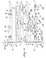
- Figures 8 to 10 illustrate a portion of a possible embodiment of the set of cams of the machine according to the invention proximate to a feed or drop A, at which the needles 6, if arranged in the lower needle cylinder 1, can form knitting both during the actuation of the needle cylinders 1, 42 of the machine in one direction of rotation 35 and in the opposite direction of rotation 36 about their own axis with respect to the set of cams.
- actuation cams of the sliders 8 of the lower needle cylinder 1 a central cam 26, a central complementary cam 27, an extraction (or lifting) cam 28, and a knockover cam 29 in the rotary motion of the needle cylinders 1, 42 in the direction of rotation 35, an extraction (or lifting) cam 30 and a knockover cam 31 in the rotary motion 36 of the needle cylinders 1, 42 in the opposite direction.
- a retraction (or lowering) cam 32 which is arranged between the extraction cam 28 and the central cam 26 and there is a retraction (or lowering) cam 33, which is arranged between the extraction cam 30 and the central cam 26 and are used to actuate the connecting elements 4 and therefore the needles 6 during the formation of knitting.
- the retraction cams 32 and 33 are formed monolithically, but they might also be provided as separate cams.
- the extraction cams 28, 28' can always be engaged, during the actuation of the needle cylinders 1, 42 in the direction of rotation 35, by the fixed heel 3a of the slider 3 or 3', and likewise the extraction cam 30 can always be engaged, during the actuation of the needle cylinders 1, 42 in the opposite direction, indicated by the arrow 36, by the fixed heel 3a of the slider 3 in order to produce the movement of the corresponding needle 6 in an extracted off-work position, while the retraction cams 32, 34, during the actuation of the needle cylinders 1, 42 with a rotary motion in the direction of rotation 35, and the retraction cam 33, during the actuation of the needle cylinders 1, 42 with a rotary motion in the opposite direction of rotation 36, can be engaged exclusively by the movable heel 4a in the active position in order to bring the slider 3 or 3' to such a level as to engage with its fixed heel the knockover cam 29 or 29' or 31 which moves the corresponding needle 6 from the extracted off-work position to the
- pressers 53, 54, 57, 60 in the region of the slider actuation cams 8, 8' pressers 61, 62, 63, 64, 65, 66, 67 in the region of the connecting element actuation cams 9, 9', and pressers 55, 58 in the intermediate region between the slider actuation cams 8, 8' and the connecting element actuation cams 9, 9', which can act respectively on the sliders 3, 3' and on the connecting elements 4, 4' in order to cause their oscillation on a radial plane of the needle cylinders 1, 42.
- pressers are fixed, i.e., rigidly coupled to the cam box or support, and therefore do not require any actuator for their operation.
- connecting element actuation cams 9, 9' there are cams which are mainly designed to actuate the connecting elements 4, 4' and therefore the sliders 3, 3' in order to actuate the transfer of the needles 6 from one needle cylinder to the other.
- a fixed upper lowering cam 51 which can be engaged by the connecting elements 4' arranged in the upper needle cylinder 42 so as to cause the lowering of the sliders 3' into the position for engaging the corresponding needle 6
- a lower lifting fixed cam 52 which can be engaged by the connecting elements 4 arranged in the lower needle cylinder 1 in order to lift the sliders 3 in the position that corresponds to the engagement of the corresponding needle 6.
- the upper lowering fixed cam 51 and the lower lifting fixed cam 52 are arranged upstream of the selection device 23 along the direction of rotation of the needle cylinders about their own axis with respect to the cam set indicated by the arrow 35.
- an upper opening presser 55 which faces the lateral surface of the upper needle cylinder 42 and can engage the heel 4b of the connecting elements 4' arranged in the upper needle cylinder 42 so as to cause the oscillation of the sliders 3' in order to move their end directed toward the corresponding needle 6 away from the bottom of the corresponding axial slot 2.
- the lateral surface of the lower needle cylinder 1 is faced by a lower lowering fixed cam 56, which can be engaged exclusively by the connecting elements 4 that are arranged in the lower needle cylinder 1 and have been moved with their movable heel 4a into the active position by said selection device 23.
- the lateral surface of the upper needle cylinder 42 is faced by an upper closure presser 57, which can engage the sliders 3' arranged in the upper needle cylinder 42 so as to cause the oscillation of the sliders 3' in order to move their end directed toward the corresponding needle 6 toward the bottom of the corresponding axial slot 2.
- the lateral surface of the lower needle cylinder 1 is faced by a lower opening presser 58, which can be engaged exclusively by the heel 4b of the connecting elements 4 that are arranged in the lower needle cylinder and have their movable heel 4a in the inactive position, i.e., do not engage the lower lowering fixed cam 56.
- the lower opening presser 58 is designed to cause the oscillation of the sliders 3 which engage it in order to move their end directed toward the corresponding needle 6 away from the bottom of the corresponding axial slot 2.
- the lateral surface of the upper needle cylinder 42 is faced by an upper lifting fixed cam 59, which can be engaged by the heel 4a of the connecting elements 4' which are arranged in the upper needle cylinder 42, and the lateral surface of the lower needle cylinder 1 is faced by a lower closure presser 60, which can be engaged by the sliders 3 in order to return the sliders 3 on which the lower opening presser 58 has acted into the position in which their end directed toward the needle 6 is close to the bottom of the corresponding axial slot 2.
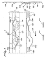
- Figures 3 to 5 illustrate the path followed by the heels 103a, 104a of a needle 106 and of a connecting element 104 which is associated therewith for the first embodiment
- Figures 8 to 10 illustrate the path followed by the heels 3a, 4a, 4b of a slider 3, 3' and of a connecting element 4, 4' which is associated therewith for the second embodiment.
- the connecting element 4, 104 does not engage with its heel 4a, 104a the retraction cam 32, 132 and therefore the slider 3 or the needle 106, after it has engaged with its fixed heel 3a, 103a the extraction cam 28, 128, is no longer lowered and passes above the central cam 26, 126.
- the needle 6, 106 remains raised, in the off-work position, and does not engage the thread or threads dispensed at the feed A being considered, as shown in Figures 3 , 8 .
- the needle 6, 106 is extracted with its upper tip or with its only tip upwardly from the needle cylinder 1, 101 in the position in which, if it were to knit, it would engage the thread or threads dispensed at the feed A or in a slightly more elevated position, so that any loop of knitting previously formed by the needle 6, 106 arranges itself on the shank of the needle 6, 106 below the latch.
- Figure 3 also illustrates the path of the fixed heel 3a of the slider 3' and of the heels 4a, 4b of the connecting element 4' which corresponds to a needle 6, arranged in the upper needle cylinder 42, which must not be moved to knit at the feed A being considered.
- the slider 3 or the needle 106 after being lifted by engagement with the extraction cam 28, 128, is lowered as an effect of the engagement of the heel 4a, 104a with the retraction cam 32, 132.
- the heel 3a of the slider 3 or the heel 103a of the needle 106 engages the central cam 26, 126 and therefore the knockover cam 29, 129, as shown in Figures 4 and 9 .
- the needle 6, 106 engages the thread or threads dispensed at the feed A being considered and forms a new loop of knitting, lowering the previously formed loop of knitting.
- a needle 6 engaged with the slider 3' in the upper needle cylinder 42 has to knit at the feed A being considered after the corresponding connecting element 4' which might have its movable heel 4a in the active position has passed at the presser 65 that caused the safe passsage of its movable heel 4a into the inactive position, it is returned with its heel 4a into the active position by the intervention of a selection device which faces the lateral surface of the upper needle cylinder 42 and is similar to the selection device 21.
- FIG. 9 also indicates the path of the heel 3a of the slider 3' and of the heels 4a, 4b of the connecting element 4' which correspond to a needle 6 which is arranged in the upper needle cylinder 42 and must be moved to knit at the feed A being considered.
- the needle 6, arranged in the lower needle cylinder 1, in the case of a double-cylinder machine, or the needle 106, arranged in the needle cylinder 101, in the case of a single-cylinder machine, must form knitting while the needle cylinders 1, 42 or the needle cylinder 101 are or is actuated with a rotary motion about their or its own axis in the direction of rotation indicated by the arrow 36, 136 which is opposite with respect to the usual direction, after the corresponding connecting element 4, 104 which might have its heel 4a, 104a in the active position has passed at the presser 63, 163 which caused the safe transfer of the heel 4a, 104a to the inactive position, it is returned with the heel 4a, 104a in the active position by the intervention of the selection device 22, 122.
- the slider 3 after being lifted by the engagement of its heel 3a with the extraction cam 30, or the needle 106, after being lifted by the engagement of its heel 103a with the extraction cam 130, is lowered due to the engagement of the heel 4a, 104a with the retraction cam 33, 133.
- the heel 3a of the slider 3 or the heel 103a of the needle 106 engages the central cam 26, 126 and therefore the knockover cam 31, 131, as shown in Figures 5 and 10 .
- the needle 6, 106 engages the thread or threads dispensed at the feed A being considered and forms a new loop of knitting, lowering the previously formed loop of knitting.
- the selection devices 21, 121 and 22, 122 it is also possible to gradually reduce and gradually increase the needles that are moved to knit at the feed being considered, performing the knitting that is usually obtained in machines of the traditional type by using devices known as hammers or pickers and flaps, eliminating the need to resort to such devices.
- the materials used, as well as the dimensions, may be any according to requirements and to the state of the art.
Landscapes
- Engineering & Computer Science (AREA)
- Textile Engineering (AREA)
- Knitting Machines (AREA)
Claims (20)
- Eine Rundstrickmaschine für Strumpfwaren oder dergleichen, die mindestens einen Nadelzylinder (1, 42, 101) umfasst, der eine vertikale Achse (1, 101a) hat und, auf seiner seitlichen Oberfläche, axiale Schlitze (2, 43, 102) hat, von denen jeder eine Nadel (6, 106) und ein Nadelbetätigungselement (10, 10', 110) aufnimmt, wobei das Betätigungselement (10, 10', 110) mit einem seiner Enden in die Nadel (6, 106) eingreifen kann, die in demselben axialen Schlitz (102) angeordnet ist, wobei die Nadel (6, 106) oder das Betätigungselement (10, 10', 110) mit mindestens einer festen Fase (3a) versehen ist, die radial aus der seitlichen Oberfläche des Nadelzylinders (1, 42, 101) herausragt, um in Betätigungsnocken (108, 109) einzugreifen, welche um die seitliche Oberfläche des Nadelzylinders (1, 42, 101) herum angeordnet sind und Pfade bestimmen, welche infolge der Betätigung des Nadelzylinders (1, 42, 101) mit einer Drehbewegung um seine eigene Achse (101a) in bezug zu den Betätigungsnocken (108, 109) von der festen Fase (3a) verfolgt werden können; dadurch gekennzeichnet, dass das Betätigungselement (10, 10', 110) mit einer Fase (104a) versehen ist, die sich auf Befehl aus einer aktiven Position, in der sie radial aus dem entsprechenden axialen Schlitz (102) des Nadelzylinders (1, 42, 101) herausragt, um in die Betätigungsnocken (108, 109) einzugreifen, in eine inaktive Position bewegen kann, in der sie in dem axialen Schlitz (102) des Nadelzylinders (1, 42, 101) enthalten ist, um nicht in die Betätigungsnocken (108, 109) einzugreifen, und umgekehrt; und dadurch, dass die Betätigungsnocken (108, 109) an mindestens einem Vorschub oder Abwurf (A) der Maschine Folgendes umfassen: einen Extraktionsnocken (128), einen Retraktionsnocken (132) und einen Abschlagnocken (129), die nacheinander entlang der Drehrichtung (136) des Nadelzylinders (1, 42, 101) in Bezug zu den Betätigungsnocken (108, 109) angeordnet sind, wobei die feste Fase (3a) immer in den Extraktionsnocken (128) eingreifen kann, um die Bewegung der entsprechenden Nadel (6, 106) in eine extrahierte Ruheposition zu erzeugen; wobei der Retraktionsnocken (132) ausschließlich von der beweglichen Fase (104a) in der aktiven Position eingreifbar ist, um die Nadel (6, 106) oder das Betätigungselement (10, 10', 110) auf eine solche Höhe zu bewegen, dass sie/es mit ihrer/seiner festen Fase (3a) in den Abschlagnocken (129) eingreift, was die Überführung der entsprechenden Nadel (6, 106) aus der extrahierten Ruheposition in die retrahierte Position veranlasst, um eine neue Strickschleife zu bilden, wobei die zuvor gebildete Strickschleife abgesenkt wird.
- Die Maschine gemäß Anspruch 1, dadurch gekennzeichnet, dass der mindestens eine Vorschub ein Vorschub ist, der ausgebildet ist, um den Faden oder die Fäden an die Nadeln (6, 106) abzugeben, um Stricken in beide Drehrichtungen des Nadelzylinders (1, 42, 101) um seine eigene Achse (101a) in Bezug auf die Betätigungsnocken (108, 109) durchzuführen, wobei sich an dem Vorschub oder Abwurf (A) ein Extraktionsnocken (128), ein Retraktionsnocken (132) und ein Abschlagnocken (129) befinden, für jede Drehrichtung (136) des Nadelzylinders (1, 42, 101) in bezug zu den Betätigungsnocken (108, 109).
- Die Maschine gemäß Anspruch 1, dadurch gekennzeichnet, dass ein zentraler Nocken (126) zwischen dem Extraktionsnocken (128) und dem Abschlagnocken (129) angeordnet ist, und dass die feste Fase (3a) infolge des Eingriffs der beweglichen Fase (104a) mit dem Retraktionsnocken (132) um die feste Fase (3a) so zu bewegen, dass sie in den Abschlagnocken (129) eingreift.
- Die Maschine gemäß einem oder mehreren der obigen Ansprüche, dadurch gekennzeichnet, dass das Betätigüngselement (10, 10', 110) Folgendes umfasst:- mindestens ein Verbindungselement (104), das an seiner Seite, die zur Außenseite des Nadelzylinders (1, 42, 101) hin gerichtet ist, mit der beweglichen Fase (104a) versehen ist, wobei das Verbindungselement (104) in der Lage ist auf einer Radialen Fläche des Nadelzylinders (1, 42, 101) zur Überführung der beweglichen Fase (104a) aus der aktiven Position, in der die bewegliche Fase (104a) radial aus dem entsprechenden axialen Schlitz (102) des Nadelzylinders (1, 42, 101) herausragt, um in entsprechende Verbindungselement-Betätigungsnocken (109) einzugreifen, welche zur seitlichen Oberfläche des Nadelzylinders (1, 42, 101) hin weisen und Pfade bilden, denen von der beweglichen Fase (104a) in der aktiven Position gefolgt werden kann, infolge der Betätigung des Nadelzylinders (1, 42, 101) mit einer Drehbewegung um seine eigene Achse (101a) in Bezug zu den Verbindungselement-Betätigungsnocken (109), auf einer radialen Ebene des Nadelzylinders (1, 42, 101) in eine inaktive Position oszillieren kann, in welcher die bewegliche Fase (104a) in dem axialen Schlitz (102) des Nadelzylinders (1, 42, 101) aufgenommen ist, so dass sie nicht in die Verbindungselement-Betätigungsnocken (109) eingreift, und umgekehrt, und- einen Wahlschalter (105), der mit einem Abschnitt versehen ist, welcher zwischen dem Verbindungselement (104) und dem Boden des axialen Schlitzes (102) des Nadelzylinders (1, 42, 101) herausragt, in dem er aufgenommen ist, wobei der Wahlschalter (105) durch Wirkung mindestens einer Auswahlvorrichtung auf einer radialen Ebene des Nadelzylinders (1, 42, 101) oszillieren kann, um die Überführung der beweglichen Fase (104a) des Verbindungselements (104) aus der inaktiven Position in die aktive Position zu veranlassen.
- Die Maschine gemäß einem oder mehreren der obigen Ansprüche, dadurch gekennzeichnet, dass der Wahlschalter (105) mit seinem Abschnitt zwischen dem Verbindungselement (104) und dem Boden des axialen Schlitzes (102) des Nadelzylinders (1, 42, 101), in dem er aufgenommen ist, in jeder Position herausragt, die von dem Verbindungselement (104) während des Betriebs der Maschine eingenommen werden kann.
- Die Maschine gemäß einem oder mehreren der obigen Ansprüche, dadurch gekennzeichnet, dass das Verbindungselement (104) um eine Drehachse (11, 111), welche senkrecht zu der radialen Ebene ist, am in Längsrichtung verlaufenden Ende der Nadel (6, 106) drehgelenkig gelagert ist, das gegenüber der Spitze oder dem Kopf der Nadel (6, 106) liegt, wobei das Verbindungselement (104) zur Überführung der beweglichen Fase (104a) aus der aktiven Position in die inaktive Position oder umgekehrt in Bezug zu der Nadel (6, 106) um die Drehachse (11, 111) oszillieren kann.
- Die Maschine gemäß einem oder mehreren der obigen Ansprüche, dadurch gekennzeichnet, dass die Nadel (6, 106) in einem mittleren Bereich ihrer Längsausdehnung eine feste Fase (3a) hat, welche radial aus dem entsprechenden axialen Schlitz (102) des Nadelzylinders (1, 42, 101) herausragt und in Nadelbetätigungsnocken (108) eingreifen kann, die zur seitlichen Oberfläche des Nadelzylinders (1, 42, 101) hin weisen und Pfade bilden, denen von der festen Fase (3a) infolge der Betätigung des Nadelzylinders (1, 42, 101) mit einer Drehbewegung um seine eigene Achse (101a) in Bezug zu den Nadelbetätigungsnocken (108) gefolgt werden kann.
- Die Maschine gemäß einem oder mehreren der obigen Ansprüche, dadurch gekennzeichnet, dass das Betätigungselement (10, 10', 110) ein intermediäres Element umfasst, welches zwischen dem Verbindungselement (104) und der Nadel (6, 106) angeordnet ist, die in einem selben axialen Schlitz (102) des Nadelzylinders (1, 42, 101) angeordnet sind, wobei das Verbindungselement (104) drehgelenkig um eine Drehachse (11, 111) an dem intermediären Element gelagert ist, wobei die Drehachse rechtwinklig zu der radialen Ebene ist und das Verbindungselement (104) zum Übergang der beweglichen Fase (104a) von der aktiven Position in die inaktive Position oder umgekehrt in Bezug zu dem intermediären Element um die Drehachse (11, 111) oszillieren kann.
- Die Maschine gemäß einem oder mehreren der obigen Ansprüche, dadurch gekennzeichnet, dass das Verbindungselement (104) an der Nadel (6, 106) oder an dem intermediären Element um die Drehachse (11, 111) nahe einem in Längsrichtung verlaufenden Ende davon drehgelenkig gelagert ist, wobei die bewegliche Fase (104a) nahe dem gegenüberliegenden in Längsrichtung verlaufenden Ende des Verbindungselements (104) herausragt.
- Die Maschine gemäß einem oder mehreren der obigen Ansprüche, dadurch gekennzeichnet, dass die drehgelenkige Anordnung zwischen der Nadel (6, 106) oder dem intermediären Element und dem Verbindungselement (104) in einem Vorsprung besteht, der an der Seite der Nadel (6, 106) oder des intermediären Elements liegt, die vom Boden des axialen Schlitzes (102) des Nadelzylinders (1, 42, 101) fort gerichtet ist, in dem sie/es sich befindet, und in einem Sitz, der den Vorsprung drehbar aufnimmt und in dem Verbindungselement (104) geformt ist.
- Die Maschine gemäß einem oder mehreren der obigen Ansprüche, dadurch gekennzeichnet, dass das Verbindungselement (104) an seinem Ende, das mit der Nadel (6, 106) oder mit dem intermediären Element verbunden ist, eine zweite Fase hat, die radial zur Außenseite des Nadelzylinders (1, 42, 101) hin herausragt.
- Die Maschine gemäß einem oder mehreren der obigen Ansprüche, dadurch gekennzeichnet, dass sie aus einer Zwei-Zylindermaschine mit einem unteren Nadelzylinder (1, 42, 101) und einem oberen Nadelzylinder (42) besteht, der über und koaxial mit dem unteren Nadelzylinder (1, 42, 101) angeordnet ist, wobei eine Vielzahl miteinander ausgerichteter axialer Schlitze (2, 43, 102) an der seitlichen Oberfläche des unteren Nadelzylinders (1, 42, 101) und an der seitlichen Oberfläche des oberen Nadelzylinders (42) geformt ist und jeder der axialen Schlitze (2, 43, 102) des unteren Nadelzylinders (1, 42, 101) und des oberen Nadelzylinders (42) ein Element zur Betätigung einer Nadel (6, 106) aufnimmt, wobei das Betätigungselement (10, 10', 110), zumindest für den unteren Nadelzylinder (1, 42, 101), Folgendes umfasst:- einen Schieber, der das intermediäre Element darstellt und nahe einem seiner in Längsrichtung verlaufenden Enden mit Mitteln zum Eingreifen in den Kopf einer Nadel (6, 106) versehen ist,- das Verbindungselement (104), drehgelenkig angeordnet am in Längsrichtung verlaufenden Ende des Schiebers, das gegenüber dem Ende liegt, das in die Nadel (6, 106) eingreifen kann,- wobei der Wahlschalter (105) einen Abschnitt hat, der zwischen dem Verbindungselement (104) und dem Boden des axialen Schlitzes (102) des Nadelzylinders (1, 42, 101), in dem er sich befindet, in jeder Position herausragt, die von dem Verbindungselement (104) während des Betriebs der Maschine eingenommen werden kann, wobei der Wahlschalter (105) durch Wirkung mindestens einer Auswahlvorrichtung zur Veranlassung der Überführung der beweglichen Fase (104a) des Verbindungselements (104) aus der inaktiven Position in die aktive Position auf einer radialen Ebene des Nadelzylinders (1, 42, 101) oszillieren kann.
- Die Maschine gemäß einem oder mehreren der obigen Ansprüche, dadurch gekennzeichnet, dass die Betätigungselemente, die im oberen Nadelzylinder (42) angeordnet sind, ebenfalls mit einer Fase ausgestattet sind, die sich auf Befehl aus einer aktiven Position, in der sie radial aus dem entsprechenden axialen Schlitz (102) des Nadelzylinders (1, 42, 101) herausragt, um in entsprechende Betätigungsnocken (109) einzugreifen, in eine inaktive Position bewegen kann, in der sie sich in dem axialen Schlitz (102) des Nadelzylinders (1, 42, 101) befindet, so dass sie nicht in die Betätigungsnocken (109) eingreift, und umgekehrt, und dadurch, dass die Betätigungsnocken (109) auch für den oberen Nadelzylinder (42) an mindestens einem Vorschub oder Abwurf (A) der Maschine einen Extraktionsnocken (128), einen Retraktionsnocken (132) und einen Abschlagnocken (129) umfassen, welche nacheinander entsprechend der Bewegung der Nadelzylinder (1, 42) in Bezug zu den Betätigungsnocken (108, 109) angeordnet sind, wobei die feste Fase (3a) immer in den Extraktionsnocken (128) eingreifen kann, um die Bewegung der entsprechenden Nadel (6, 106) in eine extrahierte Ruheposition zu veranlassen, und der Retraktionsnocken (132) ausschließlich von der beweglichen Fase (104a) in der aktiven Position gehalten werden kann, um das Betätigungselement (10, 10', 110) auf eine solche Höhe zu bewegen, dass es mit seiner festen Fase (3a) in den Abschlagnocken (129) eingreift, um die entsprechende Nadel (6, 106) zur Bildung einer neuen Strickschleife bei Absenkung der zuvor gebildeten Strickschleife aus der extrahierten Ruheposition in die retrahierte Position zu bewegen.
- Die Maschine gemäß einem oder mehreren der obigen Ansprüche, dadurch gekennzeichnet, dass die Betätigungselemente, die in den axialen Schlitzen (2, 43, 102) des oberen Nadelzylinders (42) angeordnet sind, im Wesentlichen wie die Betätigungselemente bereitgestellt werden, die in den axialen Schlitzen (2, 43, 102) des unteren Nadelzylinders (1, 42, 101) angeordnet sind.
- Die Maschine gemäß einem oder mehreren der obigen Ansprüche, dadurch gekennzeichnet, dass das Verbindungselement (104) mit einem seinem in Längsrichtung verlaufenden Ende drehgelenkig an dem in Längsrichtung verlaufenden Ende des Schiebers angeordnet ist, das gegenüber von dem Ende liegt, das in die Nadel (6, 106) eingreifen kann, um eine Drehachse (11, 111), die senkrecht zu der radialen Ebene ist.
- Die Maschine gemäß einem oder mehreren der obigen Ansprüche, dadurch gekennzeichnet, dass der Schieber zwecks Eingriffs des Kopfs der Nadel (6, 106) oder Freisetzung des Kopfs der Nadel (6, 106) an ihrem in Längsrichtung verlaufenden Ende, das gegenüber dem in Längsrichtung verlaufenden Ende liegt, welches drehgelenkig an dem Verbindungselement (104) angeordnet ist, auf einer radialen Ebene des Nadelzylinders (1, 42, 101) oszillieren kann.
- Die Maschine gemäß einem oder mehreren der obigen Ansprüche, dadurch gekennzeichnet, dass das Verbindungselement (104) an seinem Ende, das drehgelenkig an dem Schieber angeordnet ist, die zweite Fase hat, welche radial zur Außenseite des Nadelzylinders (1, 42, 101) hin herausragt, wobei die zweite Fase zum Boden des axialen Schlitzes (102) hin gedrückt werden kann, um die Oszillation des Schiebers auf der radialen Ebene in die Richtung zu erzeugen, die sein in Längsrichtung verlaufendes Ende, das zur Nadel (6, 106) hin ausgerichtet ist, vom Boden des axialen Schlitzes (102) des Nadelzylinders (1, 42, 101) fort bewegt, in dem er untergebracht ist.
- Die Maschine gemäß einem oder mehreren der obigen Ansprüche, dadurch gekennzeichnet, dass der Wahlschalter (105) in einem Bereich seiner Längsausdehnung, der von seinem Abschnitt beabstandet ist, der zwischen dem Boden des axialen Schlitzes (102), in dem er untergebracht ist, und dem Verbindungselement (104) angeordnet ist, einen Bereich hat, der von der mindestens einen Auswahlvorrichtung zum Boden des axialen Schlitzes (102) hin gedrückt werden kann, um die Oszillation des Wahlschalters (105) und folglich die Überführung der beweglichen Fase (104a) des Verbindungselements (104) aus der inaktiven Position in die aktive Position zu verursachen.
- Die Maschine gemäß einem oder mehreren der obigen Ansprüche, dadurch gekennzeichnet, dass die mindestens eine Auswahlvorrichtung ausgebildet ist, um eine Nadel-per-Nadel-Auswahl vorzunehmen, d. h., um den Wahlschalter unabhängig voneinander zu betätigen.
- Die Maschine gemäß einem oder mehreren der obigen Ansprüche, dadurch gekennzeichnet, dass sie feste Pressschienen umfasst, die seitlich zum Nadelzylinder (1, 42, 101) hin weisen und in die Fasen des Verbindungselements (104) eingreifen können, um die Oszillation des Schiebers und/oder des Verbindungselements (104) auf der radialen Ebene des Nadelzylinders (1, 42, 101) zu veranlassen.
Applications Claiming Priority (3)
| Application Number | Priority Date | Filing Date | Title |
|---|---|---|---|
| ITMI20060637 ITMI20060637A1 (it) | 2006-03-31 | 2006-03-31 | Macchina circolare per maglieria o per calzetteria o simile a doppio cilindro |
| ITMI20061378 ITMI20061378A1 (it) | 2006-07-14 | 2006-07-14 | Macchina circolare per maglieria o per calzetteria o simile |
| PCT/IB2007/000883 WO2007113659A2 (en) | 2006-03-31 | 2007-03-27 | Circular knitting machine for hosiery or the like |
Publications (2)
| Publication Number | Publication Date |
|---|---|
| EP2002041A2 EP2002041A2 (de) | 2008-12-17 |
| EP2002041B1 true EP2002041B1 (de) | 2010-07-14 |
Family
ID=38564030
Family Applications (1)
| Application Number | Title | Priority Date | Filing Date |
|---|---|---|---|
| EP07734204A Active EP2002041B1 (de) | 2006-03-31 | 2007-03-27 | Rundstrickmaschine für strumpfwaren oder dergleichen |
Country Status (6)
| Country | Link |
|---|---|
| US (1) | US7739889B2 (de) |
| EP (1) | EP2002041B1 (de) |
| JP (1) | JP5450050B2 (de) |
| KR (1) | KR101320959B1 (de) |
| DE (1) | DE602007007741D1 (de) |
| WO (1) | WO2007113659A2 (de) |
Families Citing this family (12)
| Publication number | Priority date | Publication date | Assignee | Title |
|---|---|---|---|---|
| KR100921156B1 (ko) | 2008-12-16 | 2009-10-12 | 주식회사 동성정밀 | 발가락양말 편성용 환편기 |
| US7836730B1 (en) * | 2010-04-05 | 2010-11-23 | Pai Lung Machinery Mill Co., Ltd. | Circular knitting machine jacquard needle equipped with a return structure |
| US9839420B2 (en) | 2010-09-30 | 2017-12-12 | Ethicon Llc | Tissue thickness compensator comprising at least one medicament |
| KR101488077B1 (ko) | 2013-03-05 | 2015-01-29 | (주) 태영기계 | 편직장치 |
| US9649110B2 (en) | 2013-04-16 | 2017-05-16 | Ethicon Llc | Surgical instrument comprising a closing drive and a firing drive operated from the same rotatable output |
| KR101304975B1 (ko) | 2013-07-09 | 2013-09-06 | 백기출 | 발가락양말 직조장치 및 그 직조방법 |
| ITUB20155479A1 (it) * | 2015-11-11 | 2017-05-11 | Lonati Spa | Procedimento per la preparazione di un manufatto tubolare del tipo calza o simile al prelievo automatizzato al termine della sua formazione su una macchina circolare a doppio cilindro con almeno una alimentazione o caduta e macchina circolare a doppio cilindro per la sua esecuzione. |
| KR20180067162A (ko) | 2016-12-12 | 2018-06-20 | 삼성물산 주식회사 | 호저리 편기를 이용한 편직물의 제조방법 |
| IT201700044701A1 (it) * | 2017-04-24 | 2018-10-24 | Santoni & C Spa | Macchina circolare per maglieria e metodo di movimentazione di aghi di una macchina circolare per maglieria |
| CN108456987A (zh) * | 2018-06-08 | 2018-08-28 | 绍兴汉翔精密机械制造有限公司 | 一种袜机的护针钢圈装置 |
| CN211036285U (zh) * | 2019-04-10 | 2020-07-17 | 浙江叶晓机械科技有限公司 | 一种双针筒织机 |
| CN112708996B (zh) * | 2020-12-21 | 2024-08-09 | 泉州恒毅机械有限公司 | 一种具有新型导针片的对筒机及对筒机的编织方法 |
Family Cites Families (10)
| Publication number | Priority date | Publication date | Assignee | Title |
|---|---|---|---|---|
| GB1281391A (en) * | 1969-02-25 | 1972-07-12 | Bentley Machine Dev Company Lt | Improvements in needle operating means in knitting machines |
| IT1146698B (it) * | 1981-09-10 | 1986-11-12 | Savio Spa | Procedimento di lavorazione con macchine circolari per maglieria e macchine circolari adottanti tale procedimento |
| IT1238719B (it) * | 1990-04-27 | 1993-09-01 | Conti Florentia Srl | Macchina circolare da maglieria atta a lavorare di moto alternato e di moto continuo anche a disegno |
| JP3002582B2 (ja) * | 1991-01-22 | 2000-01-24 | 日本碍子株式会社 | 端面型サーマルヘッド |
| CZ280577B6 (cs) * | 1991-12-30 | 1996-02-14 | Uniplet, A.S. | Okrouhlý pletací stroj |
| GB2264308B (en) * | 1992-02-21 | 1996-01-17 | Uniplet As | Knitting machine |
| ITBO940161A1 (it) * | 1994-04-15 | 1995-10-15 | Matec Srl | Dispositivo di selezione per selettore elastico per aghi in macchina tessile circolare |
| IT1295742B1 (it) * | 1997-02-04 | 1999-05-27 | Franco Sciacca | Metodo e attrezzatura per la selezione jacquard in una macchina tessile |
| IT1303828B1 (it) * | 1998-12-09 | 2001-02-23 | Matec Spa | Platina di trasferimento o slider per macchine circolari permaglieria o calzetteria a doppio cilindro. |
| IT1320094B1 (it) * | 2000-11-22 | 2003-11-18 | Matec Spa | Macchina circolare per maglieria o calzetteria a doppio cilindro conmantello delle camme ad elevata semplicita' strutturale. |
-
2007
- 2007-03-27 EP EP07734204A patent/EP2002041B1/de active Active
- 2007-03-27 KR KR1020087026624A patent/KR101320959B1/ko active Active
- 2007-03-27 US US12/225,911 patent/US7739889B2/en active Active
- 2007-03-27 WO PCT/IB2007/000883 patent/WO2007113659A2/en not_active Ceased
- 2007-03-27 DE DE602007007741T patent/DE602007007741D1/de active Active
- 2007-03-27 JP JP2009502249A patent/JP5450050B2/ja active Active
Also Published As
| Publication number | Publication date |
|---|---|
| DE602007007741D1 (de) | 2010-08-26 |
| JP5450050B2 (ja) | 2014-03-26 |
| KR20090005116A (ko) | 2009-01-12 |
| WO2007113659A2 (en) | 2007-10-11 |
| WO2007113659A9 (en) | 2008-04-24 |
| EP2002041A2 (de) | 2008-12-17 |
| JP2009531558A (ja) | 2009-09-03 |
| WO2007113659A3 (en) | 2008-02-14 |
| US7739889B2 (en) | 2010-06-22 |
| US20090301137A1 (en) | 2009-12-10 |
| KR101320959B1 (ko) | 2013-10-23 |
Similar Documents
| Publication | Publication Date | Title |
|---|---|---|
| US7739889B2 (en) | Circular knitting machine for hosiery or the like | |
| EP2002040B1 (de) | Rundstrickmaschine für strumpfwaren | |
| EP2002043B1 (de) | Zweizylindrige rundstrickmaschine für miederwaren und andere strickwaren | |
| BR112019022224B1 (pt) | Máquina de malharia circular e método para mover as agulhas de uma máquina de malharia circular | |
| CN101415872B (zh) | 用于袜类或类似物的圆型针织机 | |
| US7065989B2 (en) | Sinker selection device in a circular knitting machine | |
| US6609395B2 (en) | Double-cylinder circular stocking knitting machine with structurally highly simplified cam box | |
| CN101415871B (zh) | 用于袜类或类似物的圆型针织机 |
Legal Events
| Date | Code | Title | Description |
|---|---|---|---|
| PUAI | Public reference made under article 153(3) epc to a published international application that has entered the european phase |
Free format text: ORIGINAL CODE: 0009012 |
|
| 17P | Request for examination filed |
Effective date: 20080904 |
|
| AK | Designated contracting states |
Kind code of ref document: A2 Designated state(s): CZ DE FR GB |
|
| DAX | Request for extension of the european patent (deleted) | ||
| RBV | Designated contracting states (corrected) |
Designated state(s): CZ DE FR GB |
|
| 17Q | First examination report despatched |
Effective date: 20090122 |
|
| GRAP | Despatch of communication of intention to grant a patent |
Free format text: ORIGINAL CODE: EPIDOSNIGR1 |
|
| GRAS | Grant fee paid |
Free format text: ORIGINAL CODE: EPIDOSNIGR3 |
|
| GRAA | (expected) grant |
Free format text: ORIGINAL CODE: 0009210 |
|
| AK | Designated contracting states |
Kind code of ref document: B1 Designated state(s): CZ DE FR GB |
|
| REG | Reference to a national code |
Ref country code: GB Ref legal event code: FG4D |
|
| REF | Corresponds to: |
Ref document number: 602007007741 Country of ref document: DE Date of ref document: 20100826 Kind code of ref document: P |
|
| PLBE | No opposition filed within time limit |
Free format text: ORIGINAL CODE: 0009261 |
|
| STAA | Information on the status of an ep patent application or granted ep patent |
Free format text: STATUS: NO OPPOSITION FILED WITHIN TIME LIMIT |
|
| 26N | No opposition filed |
Effective date: 20110415 |
|
| REG | Reference to a national code |
Ref country code: DE Ref legal event code: R097 Ref document number: 602007007741 Country of ref document: DE Effective date: 20110415 |
|
| GBPC | Gb: european patent ceased through non-payment of renewal fee |
Effective date: 20110327 |
|
| REG | Reference to a national code |
Ref country code: FR Ref legal event code: ST Effective date: 20111130 |
|
| PG25 | Lapsed in a contracting state [announced via postgrant information from national office to epo] |
Ref country code: DE Free format text: LAPSE BECAUSE OF NON-PAYMENT OF DUE FEES Effective date: 20111001 Ref country code: FR Free format text: LAPSE BECAUSE OF NON-PAYMENT OF DUE FEES Effective date: 20110331 |
|
| REG | Reference to a national code |
Ref country code: DE Ref legal event code: R119 Ref document number: 602007007741 Country of ref document: DE Effective date: 20111001 |
|
| PG25 | Lapsed in a contracting state [announced via postgrant information from national office to epo] |
Ref country code: GB Free format text: LAPSE BECAUSE OF NON-PAYMENT OF DUE FEES Effective date: 20110327 |
|
| P01 | Opt-out of the competence of the unified patent court (upc) registered |
Effective date: 20230526 |
|
| PGFP | Annual fee paid to national office [announced via postgrant information from national office to epo] |
Ref country code: CZ Payment date: 20260316 Year of fee payment: 20 |