EP2002060B1 - Vorrichtung zum schleifen von schienen eines gleises - Google Patents
Vorrichtung zum schleifen von schienen eines gleises Download PDFInfo
- Publication number
- EP2002060B1 EP2002060B1 EP07723033A EP07723033A EP2002060B1 EP 2002060 B1 EP2002060 B1 EP 2002060B1 EP 07723033 A EP07723033 A EP 07723033A EP 07723033 A EP07723033 A EP 07723033A EP 2002060 B1 EP2002060 B1 EP 2002060B1
- Authority
- EP
- European Patent Office
- Prior art keywords
- rotation
- combustion engine
- axis
- frame
- grinding
- Prior art date
- Legal status (The legal status is an assumption and is not a legal conclusion. Google has not performed a legal analysis and makes no representation as to the accuracy of the status listed.)
- Not-in-force
Links
- 238000002485 combustion reaction Methods 0.000 claims abstract description 25
- 230000005540 biological transmission Effects 0.000 claims description 4
- 230000009466 transformation Effects 0.000 claims 1
- 230000008878 coupling Effects 0.000 description 1
- 238000010168 coupling process Methods 0.000 description 1
- 238000005859 coupling reaction Methods 0.000 description 1
- 230000001419 dependent effect Effects 0.000 description 1
Images
Classifications
-
- E—FIXED CONSTRUCTIONS
- E01—CONSTRUCTION OF ROADS, RAILWAYS, OR BRIDGES
- E01B—PERMANENT WAY; PERMANENT-WAY TOOLS; MACHINES FOR MAKING RAILWAYS OF ALL KINDS
- E01B31/00—Working rails, sleepers, baseplates, or the like, in or on the line; Machines, tools, or auxiliary devices specially designed therefor
- E01B31/02—Working rail or other metal track components on the spot
- E01B31/12—Removing metal from rails, rail joints, or baseplates, e.g. for deburring welds, reconditioning worn rails
- E01B31/17—Removing metal from rails, rail joints, or baseplates, e.g. for deburring welds, reconditioning worn rails by grinding
Definitions
- the invention relates to a device for grinding rails of a track according to the preamble of claim 1.
- Such a device is for example off DE-AS 1 274 610 known.
- the copying frame together with the - arranged directly on the grinding member - working motor is laterally pivoted to the horizontal, while the base frame remains in a vertical position. Due to the strong lateral inclination is not any type of motor can be used as a working drive.
- EP 1 178 154 B1 a device for rail grinding, in which the drive motor is an internal combustion engine. This is distanced from the grinding member mounted on a separate support frame, which in turn is connected to both the base frame and with the copy frame by means of running in the longitudinal direction of the rail axes. During the lateral pivoting of the copy frame when grinding the side surfaces of the rail head can remain in this way, the support frame with the engine in approximately horizontal position. This training is structurally relatively expensive.
- the object of the present invention is now to provide a device of the type mentioned, in which an internal combustion engine can be used in conjunction with a simplified design effort.
- the engine can be automatically rotated in proportion to the pivoting of the copy frame.
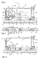
- Fig. 1 a side view of a device according to the invention for rail grinding
- Fig. 2 a plan view of the copy frame of the device together the internal combustion engine
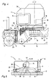
- Fig. 3 a further side view of the device in a laterally pivoted working position
- Fig. 4 a detail side view of the drive device for rotating the internal combustion engine
- Fig. 5 a schematic side view of another embodiment of the invention.
- An in Fig. 1 to 4 illustrated device 1 for grinding rails 2 of a track 3 has a bow-shaped base frame 4 and extending in the longitudinal direction rail copy frame 5, which is articulated at its two longitudinal ends on the base frame 4 and tilted to this about a running in the rail longitudinal direction pivot axis 6.
- the base frame 4 rolls off on the rail 2 by means of flanged rollers 7, while the copying frame 5 rests on the rail 2 via two mutually spaced-apart copying rollers 8.
- a controllable via a handwheel 9 pivot drive 10 is provided for lateral pivoting of the copy frame 5 relative to the base frame 4 .
- a grinding member 11 is mounted thereon with a grinding member 12 which is rotatable about a normal to the rail longitudinal axis of rotation 13 and perpendicular to a rail travel surface 14 of the rail 2 deliverable.
- a working drive 15 is an internal combustion engine 16, which - distanced from the grinding member 11 in the rail longitudinal direction - is arranged on the copy frame 5 and connected to the grinding member 11 via a drive belt 17.
- This internal combustion engine 16 has a cylinder head 34 and a crankshaft 33, which are - in a basic position of the device 1 for grinding the horizontal rail running surface 14 - both spaced horizontally and vertically away from each other, wherein the crankshaft 33 is positioned in the lower region of the engine 16 ,
- a drive device 20 is provided in the form of an angular gear 22, via which the engine 16 and a supporting disc 21 superimposed thereon is mechanically coupled to the base frame 4.
- the angle gear 22 has a vertically arranged, semi-circular toothed segment 23 which is fixedly connected to the base frame 4, wherein the center of the semicircle lies in the pivot axis 6.
- the toothed segment 23 is in engagement with a toothed pinion 24, which in turn is connected to a first bevel gear 26 via a shaft 25, which extends in the longitudinal direction of the rail and is rotatably mounted on the copying frame 5.
- a toothed pinion 24 which in turn is connected to a first bevel gear 26 via a shaft 25, which extends in the longitudinal direction of the rail and is rotatably mounted on the copying frame 5.
- This is associated with a right angle thereto, another bevel gear 27 associated with a pinion gear 28 and about a parallel to the axis of rotation 19 extending axis 29 is rotatable.
- the pinion 28 is finally in engagement with a further semicircular toothed segment 30, which is integrated in the support disk 21 of the internal combustion engine 16 is.
- the mechanical coupling by the angle gear 22 now causes a lateral pivoting of the copy frame 5 about the pivot axis 6 automatically causes a rotation of the engine 16 about the axis of rotation 19.
- the transmission ratio of the angular gear 22 is designed so that the implementation of the pivoting in the rotational movement is directly proportional, ie 1: 1, is.
- a pivoting of the copy frame 5 by 90 ° thus corresponds to a quarter turn of the engine 16 about the rotation axis 19th
- Fig. 1 and 2 is (in elevation or plan view) the device 1 when editing the horizontal rail driving surface 14 of the rail 2 shown.
- Fig. 3 is the working position of the device 1 when grinding the - in Fig. 1 facing the viewer - vertical rail head side surface 31 shown.
- the copy frame 5 has been pivoted laterally by 90 ° on the basis of the pivoting drive 10.
- the design of the internal combustion engine 16 with the arrangement of the crankshaft 33 and the cylinder head 34, which is in particular vertically distanced from each other, permits an inclination of the internal combustion engine 16 to one side (namely to the in Fig. 1, 2 and 4 right side).
- the coupled to the pivoting of the copy frame 5 rotation of the engine 16 now causes that the crankshaft 33 having portion of the engine is always positioned below the cylinder head 34, regardless of which rail side towards the copy frame 5 is pivoted.
- a variant of the invention is shown in which the Internal combustion engine 16 is arranged directly on the grinding member 11.
- the axis of rotation 19 extends in this case coaxially to the axis of rotation 13 of the grinding element 12. This eliminates the need for a separate device (eg a drive belt) for power transmission between the motor 16 and grinding member 11 away.
- a flexible shaft 30 is provided which (instead of the bevel gears 26,27 in the embodiment according to FIG Fig. 1 to 4 ) transmits the driving force between the two pinions 24 and 28.
Landscapes
- Engineering & Computer Science (AREA)
- Mechanical Engineering (AREA)
- Architecture (AREA)
- Civil Engineering (AREA)
- Structural Engineering (AREA)
- Machines For Laying And Maintaining Railways (AREA)
- Grinding Of Cylindrical And Plane Surfaces (AREA)
Description
- Die Erfindung betrifft eine Vorrichtung zum Schleifen von Schienen eines Gleises gemäß dem Oberbegriff von Anspruch 1.
- Eine derartige Vorrichtung ist beispielsweise aus
DE-AS 1 274 610 - Weiters ist aus
EP 1 178 154 B1 eine Vorrichtung zum Schienenschleifen bekannt, bei der der Antriebsmotor ein Verbrennungsmotor ist. Dieser ist vom Schleiforgan distanziert auf einem separaten Stützrahmen gelagert, der seinerseits sowohl mit dem Grundrahmen als auch mit dem Kopierrahmen anhand von in Schienenlängsrichtung verlaufenden Achsen gelenkig verbunden ist. Während der seitlichen Verschwenkung des Kopierrahmens beim Schleifen der Seitenflächen des Schienenkopfes kann auf diese Weise der Stützrahmen mit dem Verbrennungsmotor in annähernd horizontaler Lage verbleiben. Diese Ausbildung ist konstruktiv relativ aufwendig. - Es ist ferner auch bekannt, einen Verbrennungsmotor als Antriebsmotor unabhängig und separat vom - auf dem Kopierrahmen angeordneten -. Schleiforgan auf dem Grundrahmen zu lagern, wie beilspielsweise in
DE 202 10 014 U1 oderEP 0 743 395 A1 geoffenbart. Die Kraftübertragung zwischen dem Motor und dem relativ zu diesem verschwenkbaren Schleiforgan erfordert hier ebenfalls großen konstruktiven Aufwand. - Die Aufgabe der vorliegenden Erfindung liegt nun in der Schaffung einer Vorrichtung der eingangs genannten Art, bei der ein Verbrennungsmotor in Verbindung mit einem vereinfachten konstruktiven Aufwand einsetzbar ist.
- Diese Aufgabe wird erfindungsgemäß mit einer Vorrichtung der gattungsgemäßen Art durch die im Kennzeichen des Hauptanspruches angeführten Merkmale gelöst.
- Mit einer derartigen Ausbildung kann der Verbrennungsmotor automatisch proportional zur Verschwenkung des Kopierrahmens verdreht werden. Dies hat den Vorteil, dass, insbesondere in Verbindung mit den Merkmalen der Ansprüche 2 und 3, der Zylinderkopf bzw. Verbrennungsraum - bezüglich einer Vertikalen - oben und die Kurbelwelle mit dem dieser zugeordneten Ölreservoir unten bleibt. Damit ist immer und völlig unabhängig vom Verschwenkungsgrad des Kopierrahmens eine Funktionstüchtigkeit des Verbrennungsmotors gewährleistet.
- Weitere Vorteile der Erfindung ergeben sich aus den weiteren Unteransprüchen und der Zeichnungsbeschreibung.
- Im Folgenden wird die Erfindung anhand eines in der Zeichnung dargestellten Ausführungsbeispieles näher beschrieben. Es zeigen:
-
Fig. 1 eine Seitenansicht einer erfindungsgemäßen Vorrichtung zum Schienenschleifen, -
Fig. 2 eine Draufsicht auf den Kopierrahmen der Vorrichtung mitsamt dem Verbrennungsmotor, -
Fig. 3 eine weitere Seitenansicht der Vorrichtung in einer seitlich verschwenkten Arbeitsposition, -
Fig. 4 eine Detail-Seitenansicht der Antriebsvorrichtung zur Verdrehung des Verbrennungsmotors, und -
Fig. 5 eine schematisierte Seitenansicht einer anderen Ausführungsform der Erfindung. - Eine in
Fig. 1 bis 4 dargestellte Vorrichtung 1 zum Schleifen von Schienen 2 eines Gleises 3 weist einen bügelförmigen Grundrahmen 4 und einen sich in Schienenlängsrichtung erstreckenden Kopierrahmen 5 auf, der an seinen beiden Längsenden am Grundrahmen 4 angelenkt und zu diesem um eine in Schienenlängsrichtung verlaufende Schwenkachse 6 kippbar ist. Der Grundrahmen 4 rollt anhand von Spurkranzrollen 7 auf der Schiene 2 ab, während der Kopierrahmen 5 über zwei voneinander distanzierte Kopierrollen 8 auf der Schiene 2 aufliegt. Zur seitlichen Verschwenkung des Kopierrahmens 5 relativ zum Grundrahmen 4 ist ein über ein Handrad 9 bedienbarer Verschwenkantrieb 10 vorgesehen. - Etwa in Längsmitte des Kopierrahmens 5 ist auf diesem ein Schleiforgan 11 mit einem Schleifelement 12 gelagert, das um eine normal zur Schienenlängsrichtung verlaufende Rotationsachse 13 rotierbar und senkrecht zu einer Schienenfahrfläche 14 der Schiene 2 zustellbar ausgebildet ist. Als Arbeitsantrieb 15 dient ein Verbrennungsmotor 16, der - vom Schleiforgan 11 in Schienenlängsrichtung distanziert - am Kopierrahmen 5 angeordnet und mit dem Schleiforgan 11 über einen Antriebsriemen 17 verbunden ist. Dieser Verbrennungsmotor 16 weist einen Zylinderkopf 34 sowie eine Kurbelwelle 33 auf, die - in einer Grundstellung der Vorrichtung 1 zum Schleifen der horizontalen Schienenfahrfläche 14 - sowohl in horizontaler als auch in vertikaler Richtung voneinander distanziert angeordnet sind, wobei die Kurbelwelle 33 im tiefer gelegenen Bereich des Verbrennungsmotors 16 positioniert ist.
- Wie nun weiters auch anhand der
Fig. 4 im Detail zu sehen, ist der - als 4-Takt-Motor ausgeführte - Verbrennungsmotor 16 auf dem Kopierrahmen 5 in einem Schwenklager 18 um eine Drehachse 19 verdrehbar gelagert. Diese ist zwischen der Kurbelwelle 33 und dem Zylinderkopf 34 angeordnet. Zur Verdrehung des Verbrennungsmotors 16 um die Drehachse 19 ist eine Antriebsvorrichtung 20 in Form eines Winkelgetriebes 22 vorgesehen, über das der Verbrennungsmotor 16 bzw. eine diesen lagernde Tragscheibe 21 mit dem Grundrahmen 4 mechanisch gekoppelt ist. Das Winkelgetriebe 22 weist ein vertikal angeordnetes, halbkreisförmiges Zahnsegment 23 auf, das mit dem Grundrahmen 4 fest verbunden ist, wobei der Mittelpunkt des Halbkreises in der Schwenkachse 6 liegt. Das Zahnsegment 23 steht mit einem Zahnritzel 24 in Eingriff, das seinerseits über eine in Schienenlängsrichtung verlaufende und am Kopierrahmen 5 drehbar gelagerte Welle 25 mit einem ersten Kegelrad 26 verbunden ist. Diesem ist ein im rechten Winkel dazu angeordnetes, weiteres Kegelrad 27 zugeordnet, das mit einem Zahnritzel 28 verbunden und um eine parallel zur Drehachse 19 verlaufende Achse 29 rotierbar ist. Das Zahnritzel 28 steht schließlich mit einem weiteren halbkreisförmigen Zahnsegment 30 in Eingriff, das in die Tragscheibe 21 des Verbrennungsmotors 16 integriert ist. - Die mechanische Koppelung durch das Winkelgetriebe 22 bewirkt nun, dass eine seitliche Verschwenkung des Kopierrahmens 5 um die Schwenkachse 6 automatisch eine Verdrehung des Verbrennungsmotors 16 um die Drehachse 19 bewirkt. Dabei ist das Übersetzungsverhältnis des Winkelgetriebes 22 so ausgelegt, dass die Umsetzung der Verschwenk- in die Verdrehbewegung direkt proportional, also 1:1, ist. Eine Verschwenkung des Kopierrahmens 5 um 90° korrespondiert somit zu einer Vierteldrehung des Verbrennungsmotors 16 um die Drehachse 19.
- In
Fig. 1 und 2 ist (in Aufriss bzw. Grundriss) die Vorrichtung 1 beim Bearbeiten der horizontalen Schienenfahrfläche 14 der Schiene 2 gezeigt. InFig. 3 ist die Arbeitsstellung der Vorrichtung 1 beim Schleifen der - inFig. 1 dem Betrachter zugewandten - vertikalen Schienenkopfseitenfläche 31 dargestellt. Dazu wurde der Kopierrahmen 5 anhand des Verschwenkantriebs 10 um 90° seitlich verschwenkt. Die Ausbildung des Verbrennungsmotors 16 mit der voneinander insbesondere vertikal distanzierten Anordnung der Kurbelwelle 33 und des Zylinderkopfes 34 erlaubt eine Neigung des Verbrennungsmotors 16 zu einer Seite hin (nämlich zur inFig. 1, 2 und4 rechten Seite). Die an die Verschwenkung des Kopierrahmens 5 gekoppelte Verdrehung des Verbrennungsmotors 16 bewirkt nun, dass der die Kurbelwelle 33 aufweisende Bereich des Motors immer unterhalb des Zylinderkopfes 34 positioniert ist, unabhängig davon, nach welcher Schienenseite hin der Kopierrahmen 5 verschwenkt wird. - In
Fig. 5 ist eine Variante der Erfindung dargestellt, bei der der Verbrennungsmotor 16 direkt auf dem Schleiforgan 11 angeordnet ist. Die Drehachse 19 verläuft in diesem Fall koaxial zur Rotationsachse 13 des Schleifelementes 12. Dadurch fällt die Notwendigkeit einer eigenen Einrichtung (z.B. eines Antriebsriemens) zur Kraftübertragung zwischen Motor 16 und Schleiforgan 11 weg. Bei der Antriebsvorrichtung 20 ist eine flexible Welle 30 vorgesehen, die (anstelle der Kegelräder 26,27 bei der Ausführung gemäßFig. 1 bis 4 ) die Antriebskraft zwischen den beiden Zahnritzeln 24 und 28 überträgt. - Als Alternative wären auch andere Ausführungsformen der Antriebsvorrichtung 20 denkbar. So könnte diese z.B. als kinematisches Vielgelenk ausgeführt sein.
Claims (7)
- Vorrichtung zum Schleifen von Schienen (2) eines Gleises (3), mit einem auf einer Schiene abstützbaren Grundrahmen (4) und einem an diesem um eine in Schienenlängsrichtung verlaufende Schwenkachse (6) verschwenkbar angelenkten Kopierrahmen (5), auf dem ein rotierbares Schleiforgan (11) mit einer normal zur Schienenlängsrichtung verlaufenden Rotationsachse (13) sowie ein mit diesem als Arbeitsantrieb (15) verbundener Verbrennungsmotor (16) angeordnet sind, dadurch gekennzeichnet, dass der Verbrennungsmotor (16) um eine Drehachse (19) rotierbar gelagert und zur Verdrehung durch eine Antriebsvorrichtung (20) mechanisch mit dem Grundrahmen (4) gekoppelt ist.
- Vorrichtung nach Anspruch 1, dadurch gekennzeichnet, dass die Antriebsvorrichtung (20) zur Verdrehung des Verbrennungsmotors (16) um die Drehachse (19) dergestalt ausgebildet ist, dass während der Verschwenkung des Kopierrahmens (5) um die Schwenkachse (6) eine Kurbelwelle (33) des Verbrennungsmotors (16) - bezüglich einer Vertikalen - immer unterhalb eines Zylinderkopfes (34) des Verbrennungsmotors (16) zu liegen kommt.
- Vorrichtung nach Anspruch 1 oder 2, dadurch gekennzeichnet, dass die Antriebsvorrichtung (20) als Winkelgetriebe (22) zur direkt proportionalen Umsetzung der Verschwenkung des Kopierrahmens (5) um die Schwenkachse (6) in eine Verdrehung des Verbrennungsmotors (16) um die Drehachse (19) ausgebildet ist.
- Vorrichtung nach Anspruch 1 bis 3, dadurch gekennzeichnet, dass der Verbrennungsmotor (16) über einen Bereich von ±90° aus der -zum Schleifen einer horizontalen Schienenfahrfläche (14) vorgesehenen - Grundstellung um die Drehachse (19) verdrehbar ausgebildet ist.
- Vorrichtung nach Anspruch 1 bis 4, dadurch gekennzeichnet, dass der Verbrennungsmotor (16) in Schienenlängsrichtung vom Schleiforgan (11) distanziert am Kopierrahmen (5) gelagert ist.
- Vorrichtung nach Anspruch 1, dadurch gekennzeichnet, dass die Antriebsvorrichtung (20) als kinematisches Vielgelenk ausgebildet ist.
- Vorrichtung nach Anspruch 1 bis 4, dadurch gekennzeichnet, dass der Verbrennungsmotor (16) mit seiner Drehachse (19) koaxial zur Rotationsachse (13) des Schleiforgans (11) am Kopierrahmen (5) angeordnet ist.
Applications Claiming Priority (2)
| Application Number | Priority Date | Filing Date | Title |
|---|---|---|---|
| DE202006004970U DE202006004970U1 (de) | 2006-03-29 | 2006-03-29 | Vorrichtung zum Schleifen von Schienen eines Gleises |
| PCT/EP2007/001846 WO2007112815A1 (de) | 2006-03-29 | 2007-03-03 | Vorrichtung zum schleifen von schienen eines gleises |
Publications (2)
| Publication Number | Publication Date |
|---|---|
| EP2002060A1 EP2002060A1 (de) | 2008-12-17 |
| EP2002060B1 true EP2002060B1 (de) | 2011-07-06 |
Family
ID=36600008
Family Applications (1)
| Application Number | Title | Priority Date | Filing Date |
|---|---|---|---|
| EP07723033A Not-in-force EP2002060B1 (de) | 2006-03-29 | 2007-03-03 | Vorrichtung zum schleifen von schienen eines gleises |
Country Status (6)
| Country | Link |
|---|---|
| EP (1) | EP2002060B1 (de) |
| AT (1) | ATE515599T1 (de) |
| DE (1) | DE202006004970U1 (de) |
| DK (1) | DK2002060T3 (de) |
| ES (1) | ES2368602T3 (de) |
| WO (1) | WO2007112815A1 (de) |
Cited By (1)
| Publication number | Priority date | Publication date | Assignee | Title |
|---|---|---|---|---|
| CN104141265A (zh) * | 2014-07-30 | 2014-11-12 | 苏州市华宁机械制造有限公司 | 一种远程可视化水冷式铁轨侧面自动电动打磨装置 |
Families Citing this family (6)
| Publication number | Priority date | Publication date | Assignee | Title |
|---|---|---|---|---|
| DE202010007264U1 (de) * | 2010-05-26 | 2010-08-26 | Robel Bahnbaumaschinen Gmbh | Schleifmaschine zum Schleifen von Schienen eines Gleises |
| CN102407471B (zh) * | 2010-09-21 | 2014-04-23 | 兰州理工大学 | 一种钢轨底部打磨机 |
| CN102535280B (zh) * | 2012-02-13 | 2014-02-12 | 株洲时代电子技术有限公司 | 一种混合动力钢轨打磨车 |
| CN107130483B (zh) * | 2017-06-26 | 2018-11-16 | 重庆理工大学 | 一种用于钢轨打磨机的砂轮控制装置 |
| CN107034751B (zh) * | 2017-06-26 | 2018-11-16 | 重庆理工大学 | 一种钢轨打磨机 |
| CN111851176B (zh) * | 2019-12-30 | 2023-05-16 | 山东博砺思轨道交通装备科技有限公司 | 钢轨仿形打磨机 |
Family Cites Families (2)
| Publication number | Priority date | Publication date | Assignee | Title |
|---|---|---|---|---|
| DE19518457A1 (de) * | 1995-05-19 | 1996-11-21 | Robel Georg Gmbh & Co | Vorrichtung zum Schleifen von Schienen |
| DE20210021U1 (de) * | 2002-06-28 | 2002-11-14 | ROBEL Bahnbaumaschinen GmbH, 83395 Freilassing | Schleifmaschine |
-
2006
- 2006-03-29 DE DE202006004970U patent/DE202006004970U1/de not_active Expired - Lifetime
-
2007
- 2007-03-03 WO PCT/EP2007/001846 patent/WO2007112815A1/de not_active Ceased
- 2007-03-03 AT AT07723033T patent/ATE515599T1/de active
- 2007-03-03 EP EP07723033A patent/EP2002060B1/de not_active Not-in-force
- 2007-03-03 ES ES07723033T patent/ES2368602T3/es active Active
- 2007-03-03 DK DK07723033.2T patent/DK2002060T3/da active
Cited By (1)
| Publication number | Priority date | Publication date | Assignee | Title |
|---|---|---|---|---|
| CN104141265A (zh) * | 2014-07-30 | 2014-11-12 | 苏州市华宁机械制造有限公司 | 一种远程可视化水冷式铁轨侧面自动电动打磨装置 |
Also Published As
| Publication number | Publication date |
|---|---|
| ES2368602T3 (es) | 2011-11-18 |
| WO2007112815A1 (de) | 2007-10-11 |
| ATE515599T1 (de) | 2011-07-15 |
| DE202006004970U1 (de) | 2006-06-08 |
| EP2002060A1 (de) | 2008-12-17 |
| DK2002060T3 (da) | 2011-10-17 |
Similar Documents
| Publication | Publication Date | Title |
|---|---|---|
| DE2327260C3 (de) | Maschine zur Bearbeitung frischbetonierter Oberflächen | |
| DE60102187T2 (de) | Schienenprofilschleifvorrichtung | |
| DE102013208484B4 (de) | Vorrichtung zum Bearbeiten von Straßen- oder Bodenoberflächen, sowie Verfahren zum Lenken einer Straßenfräsmaschine | |
| EP2576909B1 (de) | Schleifmaschine zum schleifen von schienen eines gleises | |
| WO2007112815A1 (de) | Vorrichtung zum schleifen von schienen eines gleises | |
| DE102014209016A1 (de) | Kippbare Patientenlagerungsvorrichtung und Verfahren zum Kippen einer Patientenlagerungsvorrichtung | |
| EP2644423A2 (de) | Windabweiser | |
| EP2400056A1 (de) | Vorrichtung zum Bearbeiten der Laufflächen von Schienen durch Umfangsschleifen mit einstellbarem Schleifprofil | |
| AT403812B (de) | Maschine zum anpressen von schwellenankern | |
| DE102007014130A1 (de) | Handhabungsgerät | |
| DE102012023571B4 (de) | Kippeinrichtung zum Kippen eines Fahrerhauses und Nutzfahrzeug | |
| EP1767389A2 (de) | Schwenkschiebetür für Fahrzeuge, insbesondere Fahrgasttür für Fahrzeuge des öffentlichen Personnenverkehrs | |
| EP4298280B1 (de) | Vorrichtung und verfahren zur materialbearbeitung der herzstückspitze einer weichenanordnung | |
| EP3488972A1 (de) | Schwenkvorrichtung | |
| EP3572056B1 (de) | Tragenlagerungseinrichtung | |
| DE102021134098A1 (de) | Ausstattungsteil für ein Fahrzeug | |
| DE602006000299T2 (de) | Schneidtisch für Metallbleche | |
| DE102010045439B4 (de) | Rundtisch | |
| DE10232892B4 (de) | Einarmschwinge für ein Motorrad mit Kardanantrieb | |
| DE202015106892U1 (de) | Rückenlehne eines Kraftfahrzeugsitzes | |
| DE20106857U1 (de) | Schienentrennvorrichtung | |
| DE20214244U1 (de) | Lamellendach | |
| DE4445833A1 (de) | Bearbeitungsmaschine | |
| DE102005022398B4 (de) | Schraubvorrichtung | |
| DE10329949B4 (de) | Heftapparat mit einem wenigstens einen Heftkopf tragenden Heftzylinder |
Legal Events
| Date | Code | Title | Description |
|---|---|---|---|
| PUAI | Public reference made under article 153(3) epc to a published international application that has entered the european phase |
Free format text: ORIGINAL CODE: 0009012 |
|
| 17P | Request for examination filed |
Effective date: 20081001 |
|
| AK | Designated contracting states |
Kind code of ref document: A1 Designated state(s): AT BE BG CH CY CZ DE DK EE ES FI FR GB GR HU IE IS IT LI LT LU LV MC MT NL PL PT RO SE SI SK TR |
|
| GRAP | Despatch of communication of intention to grant a patent |
Free format text: ORIGINAL CODE: EPIDOSNIGR1 |
|
| DAX | Request for extension of the european patent (deleted) | ||
| GRAS | Grant fee paid |
Free format text: ORIGINAL CODE: EPIDOSNIGR3 |
|
| GRAA | (expected) grant |
Free format text: ORIGINAL CODE: 0009210 |
|
| AK | Designated contracting states |
Kind code of ref document: B1 Designated state(s): AT BE BG CH CY CZ DE DK EE ES FI FR GB GR HU IE IS IT LI LT LU LV MC MT NL PL PT RO SE SI SK TR |
|
| REG | Reference to a national code |
Ref country code: GB Ref legal event code: FG4D Free format text: NOT ENGLISH |
|
| REG | Reference to a national code |
Ref country code: CH Ref legal event code: EP |
|
| REG | Reference to a national code |
Ref country code: IE Ref legal event code: FG4D Free format text: LANGUAGE OF EP DOCUMENT: GERMAN |
|
| REG | Reference to a national code |
Ref country code: DE Ref legal event code: R096 Ref document number: 502007007610 Country of ref document: DE Effective date: 20110908 |
|
| REG | Reference to a national code |
Ref country code: RO Ref legal event code: EPE |
|
| REG | Reference to a national code |
Ref country code: NL Ref legal event code: T3 |
|
| REG | Reference to a national code |
Ref country code: SE Ref legal event code: TRGR |
|
| REG | Reference to a national code |
Ref country code: DK Ref legal event code: T3 |
|
| REG | Reference to a national code |
Ref country code: ES Ref legal event code: FG2A Ref document number: 2368602 Country of ref document: ES Kind code of ref document: T3 Effective date: 20111118 |
|
| PG25 | Lapsed in a contracting state [announced via postgrant information from national office to epo] |
Ref country code: SI Free format text: LAPSE BECAUSE OF FAILURE TO SUBMIT A TRANSLATION OF THE DESCRIPTION OR TO PAY THE FEE WITHIN THE PRESCRIBED TIME-LIMIT Effective date: 20110706 |
|
| PG25 | Lapsed in a contracting state [announced via postgrant information from national office to epo] |
Ref country code: LT Free format text: LAPSE BECAUSE OF FAILURE TO SUBMIT A TRANSLATION OF THE DESCRIPTION OR TO PAY THE FEE WITHIN THE PRESCRIBED TIME-LIMIT Effective date: 20110706 Ref country code: PT Free format text: LAPSE BECAUSE OF FAILURE TO SUBMIT A TRANSLATION OF THE DESCRIPTION OR TO PAY THE FEE WITHIN THE PRESCRIBED TIME-LIMIT Effective date: 20111107 Ref country code: IS Free format text: LAPSE BECAUSE OF FAILURE TO SUBMIT A TRANSLATION OF THE DESCRIPTION OR TO PAY THE FEE WITHIN THE PRESCRIBED TIME-LIMIT Effective date: 20111106 |
|
| REG | Reference to a national code |
Ref country code: IE Ref legal event code: FD4D |
|
| PG25 | Lapsed in a contracting state [announced via postgrant information from national office to epo] |
Ref country code: CY Free format text: LAPSE BECAUSE OF FAILURE TO SUBMIT A TRANSLATION OF THE DESCRIPTION OR TO PAY THE FEE WITHIN THE PRESCRIBED TIME-LIMIT Effective date: 20110706 Ref country code: GR Free format text: LAPSE BECAUSE OF FAILURE TO SUBMIT A TRANSLATION OF THE DESCRIPTION OR TO PAY THE FEE WITHIN THE PRESCRIBED TIME-LIMIT Effective date: 20111007 Ref country code: LV Free format text: LAPSE BECAUSE OF FAILURE TO SUBMIT A TRANSLATION OF THE DESCRIPTION OR TO PAY THE FEE WITHIN THE PRESCRIBED TIME-LIMIT Effective date: 20110706 Ref country code: PL Free format text: LAPSE BECAUSE OF FAILURE TO SUBMIT A TRANSLATION OF THE DESCRIPTION OR TO PAY THE FEE WITHIN THE PRESCRIBED TIME-LIMIT Effective date: 20110706 |
|
| PG25 | Lapsed in a contracting state [announced via postgrant information from national office to epo] |
Ref country code: IE Free format text: LAPSE BECAUSE OF FAILURE TO SUBMIT A TRANSLATION OF THE DESCRIPTION OR TO PAY THE FEE WITHIN THE PRESCRIBED TIME-LIMIT Effective date: 20110706 Ref country code: SK Free format text: LAPSE BECAUSE OF FAILURE TO SUBMIT A TRANSLATION OF THE DESCRIPTION OR TO PAY THE FEE WITHIN THE PRESCRIBED TIME-LIMIT Effective date: 20110706 |
|
| PLBE | No opposition filed within time limit |
Free format text: ORIGINAL CODE: 0009261 |
|
| STAA | Information on the status of an ep patent application or granted ep patent |
Free format text: STATUS: NO OPPOSITION FILED WITHIN TIME LIMIT |
|
| PG25 | Lapsed in a contracting state [announced via postgrant information from national office to epo] |
Ref country code: EE Free format text: LAPSE BECAUSE OF FAILURE TO SUBMIT A TRANSLATION OF THE DESCRIPTION OR TO PAY THE FEE WITHIN THE PRESCRIBED TIME-LIMIT Effective date: 20110706 |
|
| PGFP | Annual fee paid to national office [announced via postgrant information from national office to epo] |
Ref country code: TR Payment date: 20120228 Year of fee payment: 6 |
|
| 26N | No opposition filed |
Effective date: 20120411 |
|
| PGFP | Annual fee paid to national office [announced via postgrant information from national office to epo] |
Ref country code: IT Payment date: 20120327 Year of fee payment: 6 |
|
| REG | Reference to a national code |
Ref country code: DE Ref legal event code: R097 Ref document number: 502007007610 Country of ref document: DE Effective date: 20120411 |
|
| PG25 | Lapsed in a contracting state [announced via postgrant information from national office to epo] |
Ref country code: MC Free format text: LAPSE BECAUSE OF NON-PAYMENT OF DUE FEES Effective date: 20120331 |
|
| PGFP | Annual fee paid to national office [announced via postgrant information from national office to epo] |
Ref country code: DE Payment date: 20130322 Year of fee payment: 7 Ref country code: RO Payment date: 20130226 Year of fee payment: 7 Ref country code: CH Payment date: 20130319 Year of fee payment: 7 Ref country code: SE Payment date: 20130319 Year of fee payment: 7 Ref country code: ES Payment date: 20130320 Year of fee payment: 7 Ref country code: FI Payment date: 20130318 Year of fee payment: 7 Ref country code: DK Payment date: 20130320 Year of fee payment: 7 Ref country code: FR Payment date: 20130329 Year of fee payment: 7 Ref country code: GB Payment date: 20130318 Year of fee payment: 7 Ref country code: CZ Payment date: 20130222 Year of fee payment: 7 |
|
| PGFP | Annual fee paid to national office [announced via postgrant information from national office to epo] |
Ref country code: NL Payment date: 20130318 Year of fee payment: 7 |
|
| PG25 | Lapsed in a contracting state [announced via postgrant information from national office to epo] |
Ref country code: BG Free format text: LAPSE BECAUSE OF FAILURE TO SUBMIT A TRANSLATION OF THE DESCRIPTION OR TO PAY THE FEE WITHIN THE PRESCRIBED TIME-LIMIT Effective date: 20111006 |
|
| PGFP | Annual fee paid to national office [announced via postgrant information from national office to epo] |
Ref country code: AT Payment date: 20130222 Year of fee payment: 7 |
|
| PG25 | Lapsed in a contracting state [announced via postgrant information from national office to epo] |
Ref country code: MT Free format text: LAPSE BECAUSE OF FAILURE TO SUBMIT A TRANSLATION OF THE DESCRIPTION OR TO PAY THE FEE WITHIN THE PRESCRIBED TIME-LIMIT Effective date: 20110706 |
|
| PGFP | Annual fee paid to national office [announced via postgrant information from national office to epo] |
Ref country code: BE Payment date: 20130318 Year of fee payment: 7 |
|
| PG25 | Lapsed in a contracting state [announced via postgrant information from national office to epo] |
Ref country code: LU Free format text: LAPSE BECAUSE OF NON-PAYMENT OF DUE FEES Effective date: 20120303 |
|
| PG25 | Lapsed in a contracting state [announced via postgrant information from national office to epo] |
Ref country code: HU Free format text: LAPSE BECAUSE OF FAILURE TO SUBMIT A TRANSLATION OF THE DESCRIPTION OR TO PAY THE FEE WITHIN THE PRESCRIBED TIME-LIMIT Effective date: 20070303 |
|
| REG | Reference to a national code |
Ref country code: DE Ref legal event code: R119 Ref document number: 502007007610 Country of ref document: DE |
|
| REG | Reference to a national code |
Ref country code: DK Ref legal event code: EBP Effective date: 20140331 |
|
| REG | Reference to a national code |
Ref country code: NL Ref legal event code: V1 Effective date: 20141001 |
|
| PG25 | Lapsed in a contracting state [announced via postgrant information from national office to epo] |
Ref country code: CZ Free format text: LAPSE BECAUSE OF NON-PAYMENT OF DUE FEES Effective date: 20140303 Ref country code: FI Free format text: LAPSE BECAUSE OF NON-PAYMENT OF DUE FEES Effective date: 20140303 |
|
| REG | Reference to a national code |
Ref country code: CH Ref legal event code: PL |
|
| REG | Reference to a national code |
Ref country code: SE Ref legal event code: EUG |
|
| REG | Reference to a national code |
Ref country code: AT Ref legal event code: MM01 Ref document number: 515599 Country of ref document: AT Kind code of ref document: T Effective date: 20140303 |
|
| GBPC | Gb: european patent ceased through non-payment of renewal fee |
Effective date: 20140303 |
|
| PG25 | Lapsed in a contracting state [announced via postgrant information from national office to epo] |
Ref country code: SE Free format text: LAPSE BECAUSE OF NON-PAYMENT OF DUE FEES Effective date: 20140304 |
|
| REG | Reference to a national code |
Ref country code: FR Ref legal event code: ST Effective date: 20141128 |
|
| REG | Reference to a national code |
Ref country code: DE Ref legal event code: R119 Ref document number: 502007007610 Country of ref document: DE Effective date: 20141001 |
|
| PG25 | Lapsed in a contracting state [announced via postgrant information from national office to epo] |
Ref country code: DE Free format text: LAPSE BECAUSE OF NON-PAYMENT OF DUE FEES Effective date: 20141001 Ref country code: LI Free format text: LAPSE BECAUSE OF NON-PAYMENT OF DUE FEES Effective date: 20140331 Ref country code: CH Free format text: LAPSE BECAUSE OF NON-PAYMENT OF DUE FEES Effective date: 20140331 Ref country code: GB Free format text: LAPSE BECAUSE OF NON-PAYMENT OF DUE FEES Effective date: 20140303 Ref country code: RO Free format text: LAPSE BECAUSE OF NON-PAYMENT OF DUE FEES Effective date: 20140303 Ref country code: FR Free format text: LAPSE BECAUSE OF NON-PAYMENT OF DUE FEES Effective date: 20140331 |
|
| PG25 | Lapsed in a contracting state [announced via postgrant information from national office to epo] |
Ref country code: AT Free format text: LAPSE BECAUSE OF NON-PAYMENT OF DUE FEES Effective date: 20140303 Ref country code: NL Free format text: LAPSE BECAUSE OF NON-PAYMENT OF DUE FEES Effective date: 20141001 |
|
| PG25 | Lapsed in a contracting state [announced via postgrant information from national office to epo] |
Ref country code: IT Free format text: LAPSE BECAUSE OF NON-PAYMENT OF DUE FEES Effective date: 20140303 |
|
| REG | Reference to a national code |
Ref country code: ES Ref legal event code: FD2A Effective date: 20150424 |
|
| PG25 | Lapsed in a contracting state [announced via postgrant information from national office to epo] |
Ref country code: DK Free format text: LAPSE BECAUSE OF NON-PAYMENT OF DUE FEES Effective date: 20140331 |
|
| PG25 | Lapsed in a contracting state [announced via postgrant information from national office to epo] |
Ref country code: ES Free format text: LAPSE BECAUSE OF NON-PAYMENT OF DUE FEES Effective date: 20140304 |
|
| PG25 | Lapsed in a contracting state [announced via postgrant information from national office to epo] |
Ref country code: BE Free format text: LAPSE BECAUSE OF NON-PAYMENT OF DUE FEES Effective date: 20140331 |
|
| PG25 | Lapsed in a contracting state [announced via postgrant information from national office to epo] |
Ref country code: TR Free format text: LAPSE BECAUSE OF NON-PAYMENT OF DUE FEES Effective date: 20140303 |