EP2002076B1 - Türstopp-stiftanordnung - Google Patents
Türstopp-stiftanordnung Download PDFInfo
- Publication number
- EP2002076B1 EP2002076B1 EP07753770A EP07753770A EP2002076B1 EP 2002076 B1 EP2002076 B1 EP 2002076B1 EP 07753770 A EP07753770 A EP 07753770A EP 07753770 A EP07753770 A EP 07753770A EP 2002076 B1 EP2002076 B1 EP 2002076B1
- Authority
- EP
- European Patent Office
- Prior art keywords
- base pad
- door stop
- stop pin
- pin assembly
- pin
- Prior art date
- Legal status (The legal status is an assumption and is not a legal conclusion. Google has not performed a legal analysis and makes no representation as to the accuracy of the status listed.)
- Active
Links
Images
Classifications
-
- B—PERFORMING OPERATIONS; TRANSPORTING
- B64—AIRCRAFT; AVIATION; COSMONAUTICS
- B64C—AEROPLANES; HELICOPTERS
- B64C1/00—Fuselages; Constructional features common to fuselages, wings, stabilising surfaces or the like
- B64C1/14—Windows; Doors; Hatch covers or access panels; Surrounding frame structures; Canopies; Windscreens accessories therefor, e.g. pressure sensors, water deflectors, hinges, seals, handles, latches, windscreen wipers
-
- E—FIXED CONSTRUCTIONS
- E05—LOCKS; KEYS; WINDOW OR DOOR FITTINGS; SAFES
- E05F—DEVICES FOR MOVING WINGS INTO OPEN OR CLOSED POSITION; CHECKS FOR WINGS; WING FITTINGS NOT OTHERWISE PROVIDED FOR, CONCERNED WITH THE FUNCTIONING OF THE WING
- E05F7/00—Accessories for wings not provided for in other groups of this subclass
- E05F7/04—Arrangements affording protection against rattling
-
- E—FIXED CONSTRUCTIONS
- E05—LOCKS; KEYS; WINDOW OR DOOR FITTINGS; SAFES
- E05Y—INDEXING SCHEME ASSOCIATED WITH SUBCLASSES E05D AND E05F, RELATING TO CONSTRUCTION ELEMENTS, ELECTRIC CONTROL, POWER SUPPLY, POWER SIGNAL OR TRANSMISSION, USER INTERFACES, MOUNTING OR COUPLING, DETAILS, ACCESSORIES, AUXILIARY OPERATIONS NOT OTHERWISE PROVIDED FOR, APPLICATION THEREOF
- E05Y2900/00—Application of doors, windows, wings or fittings thereof
- E05Y2900/50—Application of doors, windows, wings or fittings thereof for vehicles
- E05Y2900/502—Application of doors, windows, wings or fittings thereof for vehicles for aircraft or spacecraft
Definitions
- This application relates generally to a door stop, and more specifically, to an aircraft door stop pin assembly which provides a positive stop between a door and a surrounding stricture, while allowing for misalignment between the two.
- Door stop pin assemblies are generally used in aircraft to ensure that contact and transmission of loads between a door assembly and a doorframe support structure is absorbed by lubricated hard points, negating any fretting or galling, which might occur due to relative motion. Relative motion between the two structures may occur due to cyclic pressurization of the fuselage and/or flight loads imposed on the external surfaces of the aircraft.
- Door stop pin assemblies may be found in applications such as aircraft passenger doors, cargo doors, and emergency exit doors, where alignment and the relative motion between the door and doorframe can be problematic-.
- Conventional door stop pin assemblies utilize a threaded stop pin having a convex spherical head on one end and a mating base pad having a concave spherical recess.
- the conventional configuration results in base pad heights that are not compatible with present design envelopes, and further requires the use of a wire, providing a static discharge path, between the pin and base pad, due to the use of lubrication between contact surfaces of the pin and the base pad.
- the invention concerns a door stop pin assembly as claimed in claim 1.
- a door stop pin assembly including a pin and a base pad.
- the pin has a concave spherical recess.
- the base pad has an open end and a closed end such that the open end has a convex spherical portion in contact with the concave spherical recess.
- a door stop pin assembly including a threaded pin and a base pad.
- the threaded pin has a concave end.
- the base pad has a complementary convex surface such that the pin and the base pad are in conductive communication with each other.
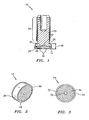
- FIGURE 1 is schematic cross section view of a door stop pin assembly for use in accordance with an embodiment of the invention
- FIGURE 2 is a perspective view of a base pad for use in accordance with an embodiment of the invention.
- FIGURE 3 a bottom plan view of the base pad for use in accordance with an embodiment of the invention.
- the door stop pin assembly 10 comprises a pin 12 and a mating base pad 14.
- the base pad 14 is able to misalign in all directions relative to the pin 12 while providing a positive stop between a door assembly (not shown) and a doorframe support structure (not shown).
- the misalignment capability of the base pad 14 reduces the onset of galling and also minimizes contact stresses between the door stop pin assembly 10 and the doorframe support structure.
- the disclosed pin 12 and base pad 14 configuration provides many significant advantages over conventional configurations including a reduced base pad height 16, which allows the use of the door stop pin assembly 10 in smaller design envelopes, and a conductive path between the pin 12 and the base pad 14, which eliminates the need for separate wires to be connected between the two.
- the pin 12 has a threaded end 18, for engagement with the door assembly, and a concave end 20, opposite the threaded end 18, which mates with the base pad 14.
- the concave end 20 further includes a concave spherical recess 22, which accepts a complementary mating shape of the base pad 14.
- the base pad 14 has a closed end 24, which in one embodiment may be a flat planar surface, providing a contact surface with the doorframe support structure, and an open end 26, within which is included a complementary convex spherical portion 28 which mates with the concave spherical recess of the pin 12.
- the base pad 14 is mechanically retained to the concave end 20 of the pin 12. In one embodiment the retention may be performed by swaging, for example, the base pad 14 to the pin 12 in a manner allowing the base pad 14 to freely rotate on the complementary spherical surfaces between the pin 12 and the base pad 14.
- the disclosed configuration of the pin 12, having a concave end 20, and the base pad 14, having a convex portion 28, provides a reduced base height 16 over conventional configurations by containing the mating surfaces between the pin 12 and the base pad 14 within the recess on the concave end 20 of the pin 12.
- Conventional configurations, which have a convex pin and a concave base pad, require the base pad to have a height capable of containing the concave portion.
- the base pad height in the conventional configuration is required to be greater than the depth of the concave portion of the base pad.
- the concave spherical recess 22 is contained within the pin 12, and the base pad 14 height may be sized pursuant to specific applications.
- the height 16 of the base pad 14 is not dependent on either the concave or convex spherical portions, as the convex spherical portion 28 is located on the base pad 14, and the outer edges of the convex spherical portion 28 are within the open end 26 of the base pad 14, therefore maintaining the contact surfaces within the concave end 20 of the pin 12.
- This disclosed configuration thus allows the base pad height 16 to be reduced significantly.
- Prototypes of the disclosed door stop pin assembly 10 have been successfully fabricated and exhibit a significant reduction in the base pad height 16 of about 30%, when compared to conventional base pad configurations having the same size pin.
- a reduced base height 16 provides for the use of the door stop pin assembly 10 in applications where tight clearance conditions have previously not allowed. The ability to reduce the base pad 14 height therefore results in smaller, lighter door assemblies, which is particularly advantageous for aerospace applications where weight restrictions and/or size and space constraints are a significant consideration.
- the base pad 14 may, in one embodiment, be fabricated from a non-galling material such as, but not limited to, Toughmet®(CuNiSn), aluminum nickel bronze, nitronic 60, copper beryllium, 660 bronze, aluminum bronze, high-lead tin bronze, copper casting alloys, plastics, composites, etc.
- the non-galling material allows the pin 12 and base pad 14 to be assembled without the use of lubrication, or with just a one-time light application of grease, between the concave and convex mating spherical surfaces.
- the use of the non-galling material may further provide a conductive path between the base pad 14 and the pin 12, as lubrication is not required between the two.
- the base pad 14 in one embodiment, may also include a conductive path between the non-galling base pad 14 and the doorframe support structure by use of, but not limited to, a "ring" 30 (having exposed material along the outer periphery of the closed end 24 as in a ring shape) or "bull's-eye" 32 (having exposed material in a ring shape along the outer periphery of the closed end 24, with the addition of a center portion of exposed material at the ring center point) configuration on the closed end 24 of the base pad 14 (illustrated in Figures 2 and 3 ).
- the disclosed door stop pin assembly 10 provides a conductive path through the entire assembly for static discharge and/or lightning strikes without additional jumper wires, grounding straps, and/or any additional electrically conductive devices.
- the closed end of the base pad 14, which contacts the doorframe support structure, may, in one embodiment, further utilize a suitable low-friction and/or wear resistant material containing a solid lubricant 34.
- the solid lubricant wear resistant material is a coating which provides wear resistance and low friction and is typically referred to in the industry as a wear resistant material, self-lubricating material, solid lubricant material, anti-fretting material, anti-galling material, solid film lubricant, or dry film lubricant.
- the lubricant material may also be in a thermosetting or thermoplastic resin system which acts as a self lubricating liner system.
- Representative solid lubricants 34 include, but are not limited to, polytetrafluoroethylene, polyetheretherketone, polyamide-imide, graphite, molybdenum disulfide, tungsten disulfide, boron nitride, mixtures of these constituent materials, and composite materials which contain these materials imbedded in a host matrix polymeric, metallic, or ceramic material.
- the wear resistant material provides anti-fretting and anti-galling protection for both the base pad 14 and the doorframe support structure.
- the low-friction characteristics of the solid lubricant 34 material greatly reduce the bending and fatigue loads imposed on door stop pin assembly 10 by allowing relative motion between and the doorframe support structure and the door stop pin assembly 10.
- the reduced bending and fatigue stresses provide an advantage in that it allows for the reduced size of the pin assembly in applications where space and weight restrictions are a concern.
Landscapes
- Engineering & Computer Science (AREA)
- Mechanical Engineering (AREA)
- Aviation & Aerospace Engineering (AREA)
- Specific Sealing Or Ventilating Devices For Doors And Windows (AREA)
- Pivots And Pivotal Connections (AREA)
- Patch Boards (AREA)
- Closing And Opening Devices For Wings, And Checks For Wings (AREA)
- Elevator Door Apparatuses (AREA)
- Special Wing (AREA)
Claims (15)
- Türanschlagstiftanordnung (10), umfassend:einen Stift (12) mit einer konkaven kugelförmigen Ausnehmung (22); undein Basispad (14) mit einem offenen Ende (26) und einen geschlossenen Ende (24), wobei das offene Ende (26) einen konvexen kugelförmigen Abschnitt (28) aufweist, dadurch gekennzeichnet, dass der konvexe kugelförmige Abschnitt (28) im offenen Ende (26) des Basispads (14) zur Gänze aufgenommen ist.
- Türanschlagstiftanordnung (10) nach Anspruch 1, wobei die Kontaktflächen der konkaven kugelförmigen Ausnehmung (22) und des konvexen kugelförmigen Abschnitts (28) ohne Schmierung oder mit einer einmaligen leichten Anwendung von Schmierfett zwischen diesen kontaktiert werden.
- Türanschlagstiftanordnung (10) nach Anspruch 1, ferner umfassend einen elektrisch leitfähigen Pfad zwischen dem Stift (12) und dem Basispad (14).
- Türanschlagsstiftanordnung (10) nach Anspruch 1, wobei das geschlossene Ende (24) des Basispads (14) ferner einen Festschmierstoff (34) oder ein Schmiermittel in einem System aus wärmehärtbarem oder thermoplastischem Harz umfasst, das als selbstschmierendes Auskleidungssystem agiert.
- Türanschlagstiftanordnung (10) nach Anspruch 1, wobei das Basispad (14) ferner einen elektrisch leitfähigen Pfad zwischen dem geschlossenen Ende (24) und einer Gegenstruktur umfasst.
- Türanschlagstiftanordnung (10) nach Anspruch 5, wobei das Basispad (14) ferner exponiertes Material mit einer ringförmigen Gestalt am geschlossenen Ende (24) umfasst.
- Türanschlagstiftanordnung (10) nach Anspruch 5, wobei das Basispad (14) ferner exponiertes Material mit einer Konfiguration in Form eines Bullenauges (32) am geschlossenen Ende (24) umfasst.
- Türanschlagstiftanordnung (10) nach Anspruch 1, wobei der Stift (12) ferner ein mit Gewinde versehenes Ende (18) umfasst.
- Türanschlagstiftanordnung (10) nach Anspruch 1, wobei das Basispad (14) aus einem abreibungsverschleißfesten Material hergestellt ist.
- Türanschlagstiftanordnung (10) nach Anspruch 1, wobei das Basispad (14) um die kugelförmigen Flächen drehbar ist, um eine Verlagerungsmöglichkeit ("misalignment capability") zwischen dem Stift (12) und dem Basispad (14) zu schaffen.
- Türanschlagstiftanordnung (10) nach Anspruch 1, wobei der Stift (12) ein Gewindestift ist; und
das Basispad (14) einen komplementären konvexen, kugelförmigen Abschnitt (28) aufweist, wobei der Stift (12) und das Basispad (14) in elektrisch leitfähiger Kommunikation miteinander stehen. - Türanschlagstiftanordnung (10) nach Anspruch 11, wobei die elektrisch leitfähige Kommunikation zwischen dem Stift (12) und dem Basispad (14) keines Schaltdrahts zwischen dem Stift (12) und dem Basispad (14) bedarf.
- Türanschlagstiftanordnung (10) nach Anspruch 11, wobei das Basispad (14) um die kugelförmigen Flächen zwischen dem Stift (12) und dem Basispad (14) drehbar ist.
- Türanschlagstiftanordnung (10) nach Anspruch 11, wobei das Basispad (14) aus einem abreibungsverschleißfesten Material hergestellt ist.
- Türanschlagstiftanordnung (10) nach Anspruch 11, wobei das Basispad (14) ferner einen elektrisch leitfähigen Pfad zwischen dem Basispad (14) und einer Gegenstruktur umfasst.
Priority Applications (1)
| Application Number | Priority Date | Filing Date | Title |
|---|---|---|---|
| PL07753770T PL2002076T3 (pl) | 2006-04-03 | 2007-03-22 | Zespół bolca odboju drzwiowego |
Applications Claiming Priority (2)
| Application Number | Priority Date | Filing Date | Title |
|---|---|---|---|
| US11/396,983 US7536746B2 (en) | 2006-04-03 | 2006-04-03 | Door stop pin assembly |
| PCT/US2007/007168 WO2007126684A1 (en) | 2006-04-03 | 2007-03-22 | Door stop pin assembly |
Publications (2)
| Publication Number | Publication Date |
|---|---|
| EP2002076A1 EP2002076A1 (de) | 2008-12-17 |
| EP2002076B1 true EP2002076B1 (de) | 2011-02-23 |
Family
ID=38462440
Family Applications (1)
| Application Number | Title | Priority Date | Filing Date |
|---|---|---|---|
| EP07753770A Active EP2002076B1 (de) | 2006-04-03 | 2007-03-22 | Türstopp-stiftanordnung |
Country Status (11)
| Country | Link |
|---|---|
| US (1) | US7536746B2 (de) |
| EP (1) | EP2002076B1 (de) |
| JP (1) | JP5144642B2 (de) |
| KR (1) | KR101302715B1 (de) |
| CN (1) | CN101410584B (de) |
| AT (1) | ATE499506T1 (de) |
| DE (1) | DE602007012671D1 (de) |
| ES (1) | ES2360256T3 (de) |
| PL (1) | PL2002076T3 (de) |
| RU (1) | RU2008143295A (de) |
| WO (1) | WO2007126684A1 (de) |
Families Citing this family (8)
| Publication number | Priority date | Publication date | Assignee | Title |
|---|---|---|---|---|
| DE102008055666B4 (de) * | 2008-11-03 | 2017-07-27 | Airbus Helicopters Deutschland GmbH | Stoppbeschlag für Flugzeugtüren |
| US8991008B2 (en) * | 2009-11-20 | 2015-03-31 | Rexnord Industries Llc | Door stop pin and related assembly |
| US8567831B2 (en) * | 2010-06-07 | 2013-10-29 | Joseph R. Roti | Fold away magnetic door stop |
| US9970480B1 (en) | 2013-04-30 | 2018-05-15 | The United States Of America As Represented By The Secretary Of The Navy | Periscope universal hull packing |
| EP3351307B1 (de) * | 2017-01-18 | 2021-06-23 | Beckman Coulter Inc. | Ausschwingzentrifuge |
| CA3061161C (en) * | 2017-04-19 | 2025-04-22 | No Slam Ltd. | DOOR STOP AND FRAME |
| US10519714B2 (en) * | 2017-06-23 | 2019-12-31 | The Boeing Company | Methods and devices for electrostatic discharge of a workpiece |
| CN120331585B (zh) * | 2025-06-12 | 2025-08-29 | 中国商用飞机有限责任公司 | 门挡装置和飞行器舱门布置系统 |
Family Cites Families (19)
| Publication number | Priority date | Publication date | Assignee | Title |
|---|---|---|---|---|
| US1394889A (en) * | 1920-08-16 | 1921-10-25 | Charles O Foedisch | Door-stop |
| US1871566A (en) * | 1930-08-30 | 1932-08-16 | Stephens Edwarde Earle | Doorcheck |
| US2073149A (en) * | 1933-10-26 | 1937-03-09 | Gen Motors Corp | Automobile door lock |
| US2140002A (en) * | 1935-12-18 | 1938-12-13 | Arthur N Dion | Door holder |
| US2496691A (en) | 1948-06-19 | 1950-02-07 | Harold H Pelzer | Doorstop and holder |
| US2885719A (en) * | 1957-08-19 | 1959-05-12 | American Seating Co | Furniture glide |
| US3187372A (en) | 1963-02-18 | 1965-06-08 | Stanley Works | Door stop |
| US3683450A (en) * | 1970-06-22 | 1972-08-15 | Rixson Inc | Friction door holder |
| US3734553A (en) * | 1971-09-13 | 1973-05-22 | Sugatsune Kogyo | Stopper for holding a door open |
| US3780345A (en) * | 1972-09-14 | 1973-12-18 | E Earman | Static electricity deshocker |
| GB2042060B (en) | 1979-02-09 | 1983-01-06 | Boeing Co | Folding plug type aircraft door |
| JPS59133191U (ja) * | 1983-02-28 | 1984-09-06 | 株式会社東芝 | 乾燥機の扉装置 |
| FR2626822B1 (fr) | 1988-02-10 | 1993-04-23 | Peugeot | Butee elastique notamment pour un element de carrosserie de vehicule automobile, et ouvrant de vehicule automobile equipe d'au moins une butee |
| JPH0728378Y2 (ja) * | 1988-08-08 | 1995-06-28 | リョービ株式会社 | 旋回兼傾倒窓のコーナーピボット |
| US5173837A (en) * | 1990-10-15 | 1992-12-22 | Compaq Computer Corporation | Hinge with two-towed clutch spring for suppressing electromagnetic interference for laptop personal computers |
| US5241725A (en) | 1992-06-26 | 1993-09-07 | The Boeing Company | Self-aligning aircraft door stop pin assembly |
| JP2594015B2 (ja) * | 1993-09-17 | 1997-03-26 | 株式会社ムラコシ精工 | 扉開閉装置 |
| US5575514A (en) * | 1995-01-05 | 1996-11-19 | Troy; Robert F. | Door-holding door stop |
| JP4331669B2 (ja) * | 2004-11-15 | 2009-09-16 | 株式会社ニシムラ | 三次元調整型ピボットヒンジ |
-
2006
- 2006-04-03 US US11/396,983 patent/US7536746B2/en active Active
-
2007
- 2007-03-22 WO PCT/US2007/007168 patent/WO2007126684A1/en not_active Ceased
- 2007-03-22 AT AT07753770T patent/ATE499506T1/de active
- 2007-03-22 KR KR1020087023305A patent/KR101302715B1/ko active Active
- 2007-03-22 ES ES07753770T patent/ES2360256T3/es active Active
- 2007-03-22 CN CN2007800115713A patent/CN101410584B/zh active Active
- 2007-03-22 RU RU2008143295/12A patent/RU2008143295A/ru unknown
- 2007-03-22 JP JP2009504199A patent/JP5144642B2/ja active Active
- 2007-03-22 DE DE602007012671T patent/DE602007012671D1/de active Active
- 2007-03-22 EP EP07753770A patent/EP2002076B1/de active Active
- 2007-03-22 PL PL07753770T patent/PL2002076T3/pl unknown
Also Published As
| Publication number | Publication date |
|---|---|
| DE602007012671D1 (de) | 2011-04-07 |
| HK1128946A1 (en) | 2009-11-13 |
| KR20090017473A (ko) | 2009-02-18 |
| CN101410584B (zh) | 2013-07-31 |
| WO2007126684A1 (en) | 2007-11-08 |
| KR101302715B1 (ko) | 2013-08-30 |
| PL2002076T3 (pl) | 2011-09-30 |
| EP2002076A1 (de) | 2008-12-17 |
| RU2008143295A (ru) | 2010-05-10 |
| ES2360256T3 (es) | 2011-06-02 |
| US7536746B2 (en) | 2009-05-26 |
| ATE499506T1 (de) | 2011-03-15 |
| CN101410584A (zh) | 2009-04-15 |
| JP5144642B2 (ja) | 2013-02-13 |
| US20070234511A1 (en) | 2007-10-11 |
| JP2009532275A (ja) | 2009-09-10 |
Similar Documents
| Publication | Publication Date | Title |
|---|---|---|
| EP2002076A1 (de) | Türstopp-stiftanordnung | |
| US10464685B2 (en) | Aircraft engine mount | |
| US20070269152A1 (en) | Truck Pivot Joint Bearing And Method Of Lubricating | |
| WO2010076306A1 (de) | Gleitelement | |
| US11906050B2 (en) | Radial shaft sealing ring | |
| WO2010129293A2 (en) | Multilayered canted coil springs and associated methods | |
| EP2787227B1 (de) | Gleitelement und lager | |
| CN105276007B (zh) | 导电轴承系统及形成导电轴承的方法 | |
| GB2384033A (en) | Crosshead bearing comprising resin layer | |
| EP2876314A1 (de) | Befestigungselement von Teilen einer Montageanordnung | |
| US4579712A (en) | Composite material for sliding member having graphite-containing phosphor bronze sintered layer and method of manufacturing the same | |
| GB2448067A (en) | Sliding member | |
| US5241725A (en) | Self-aligning aircraft door stop pin assembly | |
| EP4155581A1 (de) | Polymergewindeeinsatz für hochlast-leitspindel und -mutter | |
| HK1128946B (zh) | 门挡销组件 | |
| EP3486501A1 (de) | Aktuatoranordnung mit selbstschmierenden komponenten | |
| EP3943764B1 (de) | Lager, kupplungsmechanismus zur verwendung darin und verfahren zur anwendung einer vorspannung zur verwendung im kupplungsmechanismus | |
| CN111164317A (zh) | 滑动轴承 | |
| KR20220112695A (ko) | 감속기 | |
| EP3543322B1 (de) | Gleitelement | |
| DE102020208821A1 (de) | Kippsegmentlager | |
| US6568906B2 (en) | Conformal sliding bearing | |
| EP3543295A1 (de) | Harzzusammensetzung und gleitelement | |
| CN109115055A (zh) | 一种固体助推器连接解锁装置 | |
| DE102010042074B3 (de) | Lagergehäuse und Lageranordnung |
Legal Events
| Date | Code | Title | Description |
|---|---|---|---|
| PUAI | Public reference made under article 153(3) epc to a published international application that has entered the european phase |
Free format text: ORIGINAL CODE: 0009012 |
|
| 17P | Request for examination filed |
Effective date: 20080902 |
|
| AK | Designated contracting states |
Kind code of ref document: A1 Designated state(s): AT BE BG CH CY CZ DE DK EE ES FI FR GB GR HU IE IS IT LI LT LU LV MC MT NL PL PT RO SE SI SK TR |
|
| 17Q | First examination report despatched |
Effective date: 20090720 |
|
| GRAP | Despatch of communication of intention to grant a patent |
Free format text: ORIGINAL CODE: EPIDOSNIGR1 |
|
| DAX | Request for extension of the european patent (deleted) | ||
| GRAS | Grant fee paid |
Free format text: ORIGINAL CODE: EPIDOSNIGR3 |
|
| GRAA | (expected) grant |
Free format text: ORIGINAL CODE: 0009210 |
|
| AK | Designated contracting states |
Kind code of ref document: B1 Designated state(s): AT BE BG CH CY CZ DE DK EE ES FI FR GB GR HU IE IS IT LI LT LU LV MC MT NL PL PT RO SE SI SK TR |
|
| REG | Reference to a national code |
Ref country code: GB Ref legal event code: FG4D |
|
| REG | Reference to a national code |
Ref country code: CH Ref legal event code: EP |
|
| REG | Reference to a national code |
Ref country code: IE Ref legal event code: FG4D |
|
| REF | Corresponds to: |
Ref document number: 602007012671 Country of ref document: DE Date of ref document: 20110407 Kind code of ref document: P |
|
| REG | Reference to a national code |
Ref country code: DE Ref legal event code: R096 Ref document number: 602007012671 Country of ref document: DE Effective date: 20110407 |
|
| REG | Reference to a national code |
Ref country code: ES Ref legal event code: FG2A Ref document number: 2360256 Country of ref document: ES Kind code of ref document: T3 Effective date: 20110602 |
|
| REG | Reference to a national code |
Ref country code: NL Ref legal event code: VDEP Effective date: 20110223 |
|
| LTIE | Lt: invalidation of european patent or patent extension |
Effective date: 20110223 |
|
| PG25 | Lapsed in a contracting state [announced via postgrant information from national office to epo] |
Ref country code: SE Free format text: LAPSE BECAUSE OF FAILURE TO SUBMIT A TRANSLATION OF THE DESCRIPTION OR TO PAY THE FEE WITHIN THE PRESCRIBED TIME-LIMIT Effective date: 20110223 Ref country code: LT Free format text: LAPSE BECAUSE OF FAILURE TO SUBMIT A TRANSLATION OF THE DESCRIPTION OR TO PAY THE FEE WITHIN THE PRESCRIBED TIME-LIMIT Effective date: 20110223 Ref country code: PT Free format text: LAPSE BECAUSE OF FAILURE TO SUBMIT A TRANSLATION OF THE DESCRIPTION OR TO PAY THE FEE WITHIN THE PRESCRIBED TIME-LIMIT Effective date: 20110623 Ref country code: GR Free format text: LAPSE BECAUSE OF FAILURE TO SUBMIT A TRANSLATION OF THE DESCRIPTION OR TO PAY THE FEE WITHIN THE PRESCRIBED TIME-LIMIT Effective date: 20110524 Ref country code: LV Free format text: LAPSE BECAUSE OF FAILURE TO SUBMIT A TRANSLATION OF THE DESCRIPTION OR TO PAY THE FEE WITHIN THE PRESCRIBED TIME-LIMIT Effective date: 20110223 |
|
| PG25 | Lapsed in a contracting state [announced via postgrant information from national office to epo] |
Ref country code: FI Free format text: LAPSE BECAUSE OF FAILURE TO SUBMIT A TRANSLATION OF THE DESCRIPTION OR TO PAY THE FEE WITHIN THE PRESCRIBED TIME-LIMIT Effective date: 20110223 Ref country code: CY Free format text: LAPSE BECAUSE OF FAILURE TO SUBMIT A TRANSLATION OF THE DESCRIPTION OR TO PAY THE FEE WITHIN THE PRESCRIBED TIME-LIMIT Effective date: 20110223 Ref country code: NL Free format text: LAPSE BECAUSE OF FAILURE TO SUBMIT A TRANSLATION OF THE DESCRIPTION OR TO PAY THE FEE WITHIN THE PRESCRIBED TIME-LIMIT Effective date: 20110223 Ref country code: BE Free format text: LAPSE BECAUSE OF FAILURE TO SUBMIT A TRANSLATION OF THE DESCRIPTION OR TO PAY THE FEE WITHIN THE PRESCRIBED TIME-LIMIT Effective date: 20110223 Ref country code: SI Free format text: LAPSE BECAUSE OF FAILURE TO SUBMIT A TRANSLATION OF THE DESCRIPTION OR TO PAY THE FEE WITHIN THE PRESCRIBED TIME-LIMIT Effective date: 20110223 Ref country code: BG Free format text: LAPSE BECAUSE OF FAILURE TO SUBMIT A TRANSLATION OF THE DESCRIPTION OR TO PAY THE FEE WITHIN THE PRESCRIBED TIME-LIMIT Effective date: 20110523 |
|
| REG | Reference to a national code |
Ref country code: PL Ref legal event code: T3 |
|
| PG25 | Lapsed in a contracting state [announced via postgrant information from national office to epo] |
Ref country code: EE Free format text: LAPSE BECAUSE OF FAILURE TO SUBMIT A TRANSLATION OF THE DESCRIPTION OR TO PAY THE FEE WITHIN THE PRESCRIBED TIME-LIMIT Effective date: 20110223 Ref country code: MC Free format text: LAPSE BECAUSE OF NON-PAYMENT OF DUE FEES Effective date: 20110331 Ref country code: DK Free format text: LAPSE BECAUSE OF FAILURE TO SUBMIT A TRANSLATION OF THE DESCRIPTION OR TO PAY THE FEE WITHIN THE PRESCRIBED TIME-LIMIT Effective date: 20110223 |
|
| REG | Reference to a national code |
Ref country code: CH Ref legal event code: PL |
|
| PG25 | Lapsed in a contracting state [announced via postgrant information from national office to epo] |
Ref country code: SK Free format text: LAPSE BECAUSE OF FAILURE TO SUBMIT A TRANSLATION OF THE DESCRIPTION OR TO PAY THE FEE WITHIN THE PRESCRIBED TIME-LIMIT Effective date: 20110223 Ref country code: RO Free format text: LAPSE BECAUSE OF FAILURE TO SUBMIT A TRANSLATION OF THE DESCRIPTION OR TO PAY THE FEE WITHIN THE PRESCRIBED TIME-LIMIT Effective date: 20110223 |
|
| PG25 | Lapsed in a contracting state [announced via postgrant information from national office to epo] |
Ref country code: MT Free format text: LAPSE BECAUSE OF FAILURE TO SUBMIT A TRANSLATION OF THE DESCRIPTION OR TO PAY THE FEE WITHIN THE PRESCRIBED TIME-LIMIT Effective date: 20110223 |
|
| PLBE | No opposition filed within time limit |
Free format text: ORIGINAL CODE: 0009261 |
|
| STAA | Information on the status of an ep patent application or granted ep patent |
Free format text: STATUS: NO OPPOSITION FILED WITHIN TIME LIMIT |
|
| REG | Reference to a national code |
Ref country code: IE Ref legal event code: MM4A |
|
| PG25 | Lapsed in a contracting state [announced via postgrant information from national office to epo] |
Ref country code: CH Free format text: LAPSE BECAUSE OF NON-PAYMENT OF DUE FEES Effective date: 20110331 Ref country code: IE Free format text: LAPSE BECAUSE OF NON-PAYMENT OF DUE FEES Effective date: 20110322 Ref country code: LI Free format text: LAPSE BECAUSE OF NON-PAYMENT OF DUE FEES Effective date: 20110331 |
|
| 26N | No opposition filed |
Effective date: 20111124 |
|
| REG | Reference to a national code |
Ref country code: DE Ref legal event code: R097 Ref document number: 602007012671 Country of ref document: DE Effective date: 20111124 |
|
| PG25 | Lapsed in a contracting state [announced via postgrant information from national office to epo] |
Ref country code: LU Free format text: LAPSE BECAUSE OF NON-PAYMENT OF DUE FEES Effective date: 20110322 |
|
| PG25 | Lapsed in a contracting state [announced via postgrant information from national office to epo] |
Ref country code: IS Free format text: LAPSE BECAUSE OF FAILURE TO SUBMIT A TRANSLATION OF THE DESCRIPTION OR TO PAY THE FEE WITHIN THE PRESCRIBED TIME-LIMIT Effective date: 20110223 |
|
| PG25 | Lapsed in a contracting state [announced via postgrant information from national office to epo] |
Ref country code: TR Free format text: LAPSE BECAUSE OF FAILURE TO SUBMIT A TRANSLATION OF THE DESCRIPTION OR TO PAY THE FEE WITHIN THE PRESCRIBED TIME-LIMIT Effective date: 20110223 |
|
| PG25 | Lapsed in a contracting state [announced via postgrant information from national office to epo] |
Ref country code: HU Free format text: LAPSE BECAUSE OF FAILURE TO SUBMIT A TRANSLATION OF THE DESCRIPTION OR TO PAY THE FEE WITHIN THE PRESCRIBED TIME-LIMIT Effective date: 20110223 |
|
| REG | Reference to a national code |
Ref country code: FR Ref legal event code: PLFP Year of fee payment: 10 |
|
| REG | Reference to a national code |
Ref country code: FR Ref legal event code: PLFP Year of fee payment: 11 |
|
| REG | Reference to a national code |
Ref country code: FR Ref legal event code: PLFP Year of fee payment: 12 |
|
| P01 | Opt-out of the competence of the unified patent court (upc) registered |
Effective date: 20230530 |
|
| PGFP | Annual fee paid to national office [announced via postgrant information from national office to epo] |
Ref country code: AT Payment date: 20250225 Year of fee payment: 19 |
|
| PGFP | Annual fee paid to national office [announced via postgrant information from national office to epo] |
Ref country code: PL Payment date: 20250117 Year of fee payment: 19 Ref country code: CZ Payment date: 20250228 Year of fee payment: 19 |
|
| PGFP | Annual fee paid to national office [announced via postgrant information from national office to epo] |
Ref country code: IT Payment date: 20250211 Year of fee payment: 19 |
|
| PGFP | Annual fee paid to national office [announced via postgrant information from national office to epo] |
Ref country code: ES Payment date: 20250404 Year of fee payment: 19 |
|
| PGFP | Annual fee paid to national office [announced via postgrant information from national office to epo] |
Ref country code: FR Payment date: 20251231 Year of fee payment: 20 |
|
| PGFP | Annual fee paid to national office [announced via postgrant information from national office to epo] |
Ref country code: GB Payment date: 20260106 Year of fee payment: 20 |
|
| PGFP | Annual fee paid to national office [announced via postgrant information from national office to epo] |
Ref country code: DE Payment date: 20260102 Year of fee payment: 20 |