EP2002146B1 - Power-shift transmission for a commercial vehicle - Google Patents
Power-shift transmission for a commercial vehicle Download PDFInfo
- Publication number
- EP2002146B1 EP2002146B1 EP07723690A EP07723690A EP2002146B1 EP 2002146 B1 EP2002146 B1 EP 2002146B1 EP 07723690 A EP07723690 A EP 07723690A EP 07723690 A EP07723690 A EP 07723690A EP 2002146 B1 EP2002146 B1 EP 2002146B1
- Authority
- EP
- European Patent Office
- Prior art keywords
- gears
- power
- gear
- shift transmission
- input
- Prior art date
- Legal status (The legal status is an assumption and is not a legal conclusion. Google has not performed a legal analysis and makes no representation as to the accuracy of the status listed.)
- Ceased
Links
Images




Classifications
-
- F—MECHANICAL ENGINEERING; LIGHTING; HEATING; WEAPONS; BLASTING
- F16—ENGINEERING ELEMENTS AND UNITS; GENERAL MEASURES FOR PRODUCING AND MAINTAINING EFFECTIVE FUNCTIONING OF MACHINES OR INSTALLATIONS; THERMAL INSULATION IN GENERAL
- F16H—GEARING
- F16H37/00—Combinations of mechanical gearings, not provided for in groups F16H1/00 - F16H35/00
- F16H37/02—Combinations of mechanical gearings, not provided for in groups F16H1/00 - F16H35/00 comprising essentially only toothed or friction gearings
- F16H37/04—Combinations of toothed gearings only
- F16H37/042—Combinations of toothed gearings only change gear transmissions in group arrangement
- F16H37/046—Combinations of toothed gearings only change gear transmissions in group arrangement with an additional planetary gear train, e.g. creep gear, overdrive
-
- F—MECHANICAL ENGINEERING; LIGHTING; HEATING; WEAPONS; BLASTING
- F16—ENGINEERING ELEMENTS AND UNITS; GENERAL MEASURES FOR PRODUCING AND MAINTAINING EFFECTIVE FUNCTIONING OF MACHINES OR INSTALLATIONS; THERMAL INSULATION IN GENERAL
- F16H—GEARING
- F16H37/00—Combinations of mechanical gearings, not provided for in groups F16H1/00 - F16H35/00
- F16H37/02—Combinations of mechanical gearings, not provided for in groups F16H1/00 - F16H35/00 comprising essentially only toothed or friction gearings
- F16H37/04—Combinations of toothed gearings only
- F16H37/042—Combinations of toothed gearings only change gear transmissions in group arrangement
-
- F—MECHANICAL ENGINEERING; LIGHTING; HEATING; WEAPONS; BLASTING
- F16—ENGINEERING ELEMENTS AND UNITS; GENERAL MEASURES FOR PRODUCING AND MAINTAINING EFFECTIVE FUNCTIONING OF MACHINES OR INSTALLATIONS; THERMAL INSULATION IN GENERAL
- F16H—GEARING
- F16H3/00—Toothed gearings for conveying rotary motion with variable gear ratio or for reversing rotary motion
- F16H3/02—Toothed gearings for conveying rotary motion with variable gear ratio or for reversing rotary motion without gears having orbital motion
- F16H3/08—Toothed gearings for conveying rotary motion with variable gear ratio or for reversing rotary motion without gears having orbital motion exclusively or essentially with continuously meshing gears, that can be disengaged from their shafts
- F16H3/12—Toothed gearings for conveying rotary motion with variable gear ratio or for reversing rotary motion without gears having orbital motion exclusively or essentially with continuously meshing gears, that can be disengaged from their shafts with means for synchronisation not incorporated in the clutches
- F16H2003/123—Toothed gearings for conveying rotary motion with variable gear ratio or for reversing rotary motion without gears having orbital motion exclusively or essentially with continuously meshing gears, that can be disengaged from their shafts with means for synchronisation not incorporated in the clutches using a brake
-
- F—MECHANICAL ENGINEERING; LIGHTING; HEATING; WEAPONS; BLASTING
- F16—ENGINEERING ELEMENTS AND UNITS; GENERAL MEASURES FOR PRODUCING AND MAINTAINING EFFECTIVE FUNCTIONING OF MACHINES OR INSTALLATIONS; THERMAL INSULATION IN GENERAL
- F16H—GEARING
- F16H2200/00—Transmissions for multiple ratios
- F16H2200/003—Transmissions for multiple ratios characterised by the number of forward speeds
- F16H2200/0065—Transmissions for multiple ratios characterised by the number of forward speeds the gear ratios comprising nine forward speeds
-
- F—MECHANICAL ENGINEERING; LIGHTING; HEATING; WEAPONS; BLASTING
- F16—ENGINEERING ELEMENTS AND UNITS; GENERAL MEASURES FOR PRODUCING AND MAINTAINING EFFECTIVE FUNCTIONING OF MACHINES OR INSTALLATIONS; THERMAL INSULATION IN GENERAL
- F16H—GEARING
- F16H3/00—Toothed gearings for conveying rotary motion with variable gear ratio or for reversing rotary motion
- F16H3/006—Toothed gearings for conveying rotary motion with variable gear ratio or for reversing rotary motion power being selectively transmitted by parallel flow paths, e.g. dual clutch transmissions
-
- F—MECHANICAL ENGINEERING; LIGHTING; HEATING; WEAPONS; BLASTING
- F16—ENGINEERING ELEMENTS AND UNITS; GENERAL MEASURES FOR PRODUCING AND MAINTAINING EFFECTIVE FUNCTIONING OF MACHINES OR INSTALLATIONS; THERMAL INSULATION IN GENERAL
- F16H—GEARING
- F16H3/00—Toothed gearings for conveying rotary motion with variable gear ratio or for reversing rotary motion
- F16H3/02—Toothed gearings for conveying rotary motion with variable gear ratio or for reversing rotary motion without gears having orbital motion
- F16H3/08—Toothed gearings for conveying rotary motion with variable gear ratio or for reversing rotary motion without gears having orbital motion exclusively or essentially with continuously meshing gears, that can be disengaged from their shafts
- F16H3/087—Toothed gearings for conveying rotary motion with variable gear ratio or for reversing rotary motion without gears having orbital motion exclusively or essentially with continuously meshing gears, that can be disengaged from their shafts characterised by the disposition of the gears
- F16H3/091—Toothed gearings for conveying rotary motion with variable gear ratio or for reversing rotary motion without gears having orbital motion exclusively or essentially with continuously meshing gears, that can be disengaged from their shafts characterised by the disposition of the gears including a single countershaft
- F16H3/0915—Toothed gearings for conveying rotary motion with variable gear ratio or for reversing rotary motion without gears having orbital motion exclusively or essentially with continuously meshing gears, that can be disengaged from their shafts characterised by the disposition of the gears including a single countershaft with coaxial input and output shafts
-
- F—MECHANICAL ENGINEERING; LIGHTING; HEATING; WEAPONS; BLASTING
- F16—ENGINEERING ELEMENTS AND UNITS; GENERAL MEASURES FOR PRODUCING AND MAINTAINING EFFECTIVE FUNCTIONING OF MACHINES OR INSTALLATIONS; THERMAL INSULATION IN GENERAL
- F16H—GEARING
- F16H3/00—Toothed gearings for conveying rotary motion with variable gear ratio or for reversing rotary motion
- F16H3/02—Toothed gearings for conveying rotary motion with variable gear ratio or for reversing rotary motion without gears having orbital motion
- F16H3/08—Toothed gearings for conveying rotary motion with variable gear ratio or for reversing rotary motion without gears having orbital motion exclusively or essentially with continuously meshing gears, that can be disengaged from their shafts
- F16H3/087—Toothed gearings for conveying rotary motion with variable gear ratio or for reversing rotary motion without gears having orbital motion exclusively or essentially with continuously meshing gears, that can be disengaged from their shafts characterised by the disposition of the gears
- F16H3/093—Toothed gearings for conveying rotary motion with variable gear ratio or for reversing rotary motion without gears having orbital motion exclusively or essentially with continuously meshing gears, that can be disengaged from their shafts characterised by the disposition of the gears with two or more countershafts
- F16H3/095—Toothed gearings for conveying rotary motion with variable gear ratio or for reversing rotary motion without gears having orbital motion exclusively or essentially with continuously meshing gears, that can be disengaged from their shafts characterised by the disposition of the gears with two or more countershafts with means for ensuring an even distribution of torque between the countershafts
-
- Y—GENERAL TAGGING OF NEW TECHNOLOGICAL DEVELOPMENTS; GENERAL TAGGING OF CROSS-SECTIONAL TECHNOLOGIES SPANNING OVER SEVERAL SECTIONS OF THE IPC; TECHNICAL SUBJECTS COVERED BY FORMER USPC CROSS-REFERENCE ART COLLECTIONS [XRACs] AND DIGESTS
- Y10—TECHNICAL SUBJECTS COVERED BY FORMER USPC
- Y10T—TECHNICAL SUBJECTS COVERED BY FORMER US CLASSIFICATION
- Y10T74/00—Machine element or mechanism
- Y10T74/19—Gearing
- Y10T74/19167—In series plural interchangeably locked nonplanetary units
-
- Y—GENERAL TAGGING OF NEW TECHNOLOGICAL DEVELOPMENTS; GENERAL TAGGING OF CROSS-SECTIONAL TECHNOLOGIES SPANNING OVER SEVERAL SECTIONS OF THE IPC; TECHNICAL SUBJECTS COVERED BY FORMER USPC CROSS-REFERENCE ART COLLECTIONS [XRACs] AND DIGESTS
- Y10—TECHNICAL SUBJECTS COVERED BY FORMER USPC
- Y10T—TECHNICAL SUBJECTS COVERED BY FORMER US CLASSIFICATION
- Y10T74/00—Machine element or mechanism
- Y10T74/19—Gearing
- Y10T74/19219—Interchangeably locked
- Y10T74/19233—Plurality of counter shafts
Definitions
- the invention relates to a power shift transmission for a commercial vehicle with a split group, a main group and a range group.
- WO 00/39484 discloses a sequentially and traction interruption-free switchable transmission for a motor vehicle, in particular a passenger car, with six forward gears.
- a motor vehicle in particular a passenger car
- six forward gears In order to enable a large variability in terms of traction interruption-free switching operations, even with multiple upshifts or downshifts, the same gears in the transmission for different power flows through different switching elements and different input shafts associated with a dual clutch are possible.
- a loose wheel mounted on an input shaft gear of an input constant on both sides of the idler gear acting switching elements can be selectively coupled to each input shaft, so that this idler gear is driven by both clutches and two input shafts.
- the transmission further has two countershafts, each driven by a Einganskonstanten, wherein one of the countershafts is formed as a hollow shaft, which is arranged coaxially to the other countershaft and is mounted radially inwardly relative to the other countershaft. From the countershafts an output to an output shaft is possible in three respective forward gears associated gear levels and a gear associated with a reverse gear level with interposition further switching elements.
- the transmission has a direct gear, for which an input shaft can be coupled to the output shaft of the transmission without the interposition of rolling gear connections.
- the present invention has for its object to provide a usable for a commercial vehicle powershift transmission, which is improved in terms of design effort, in particular the switching elements to be used, the bearings and the installation space, the sequential powershifting, while enabling multiple upshifts or multiple downshifts without interruption of traction.
- Such a transmission is initially characterized by the series connection of a split group, a main group and a range group, whereby a high variability of the possible gears is given under reasonable construction costs, over which even heavy commercial vehicles with varying driving conditions are finely driven.
- the present invention is based on the basic idea WO 00/39484 in view of enabling connection of a loose wheel of an input constant with both input shafts.
- a loose wheel can be both a rotatably mounted idler gear relative to the input shafts, ie a drive wheel of the input constants, as well as a loose gear assigned to the countershaft, ie an output-side gear of the input constants act.
- the creation a possibility of connecting the idler gear with both input shafts and thus both clutches leads for a given number of gear pairs and tooth planes to ensure many different power shift options, even for double high and double downshifts under load, without additional gear pairs are provided.
- the selectively drivable input constant can be brought into operative connection with the two input shafts and couplings in a structurally simple, space-saving manner and with high efficiency or with low losses due to tooth engagement.
- a gear and a change in these can be done either via one of the two clutches.
- a suitable control of an overload of a clutch for example during a start-up, a different wear of the clutches and any impairments of a clutch, bill be taken into account. This can also lead to an extension of maintenance intervals.
- one of the two input shafts can be connected in a rotationally fixed manner to a main shaft of the main group via a switching element, so that a direct drive through split group and main group takes place with an optimum efficiency.
- a range group By connecting a range group, such an advantageous operation can be used for a plurality of different transmission gears depending on the switching state of the range group.
- the range group also has a direct gear, in which no rolling gears are interposed in the power flow in the range group.
- the overall transmission has gears with good efficiency, in which a direct drive through the split group and main group takes place, and a gear with further improved efficiency, in which a direct course is given by split group, main group and range group.
- the or a countershaft associated gears may all be formed as fixed wheels, whereby switching elements and additional space in the countershaft can be saved. Furthermore, under certain circumstances, an actuation of the switching elements is all possible in the region of the common axis of the input shafts and the output shaft, whereby compact, "centralized” actuators and electrical control units for this are possible.
- all switching elements or sleeves can be arranged so that they are arranged exclusively coaxially with the input shafts.
- the actuator for the operation of the switching elements can be designed to be particularly compact and inexpensive.
- only a countershaft can be provided, which then carries only fixed wheels.
- Such a use of a single countershaft has cost, weight and space advantages, which preclude the disadvantage of high shaft deflection and high bearing forces, since the toothing forces on the force-transmitting teeth are anxious to push the two parallel spaced waves away from each other.
- Such a high shaft deflection can, for example, by use of a rolling bearing according to DE 10332210 A1 be prevented.
- Another advantageous possibility for preventing high shaft deflections and bearing loads is the use of two countershafts, at least partially made equal, whose forces can cancel each other out.
- the two countershafts may also be provided exclusively with fixed wheels and / or wear no shift sleeves.
- the input-side gears of the input constants are not used only for transferring the drive movement to the countershaft. Rather, the drive torque is first transmitted from an input shaft to the countershaft via a first input constant transfer. In this first input constant, the idler gear which can be selectively connected to both input shafts is effective. Via a further "input constant", the power is fed back from the countershaft to the other input shaft, which is connected in a rotationally fixed manner to the main shaft of the main gear in a "reverse” power flow. Gear pairs of the main group are thus not used for this gear.
- a particularly compact design of the transmission results in the case when the connection between the input shaft (or associated gear for power return) and the main shaft of the main group is made via the switching element, which causes a connection of the input shaft to the main shaft in the direct gear.
- a further improvement of the efficiency can be achieved in that in the direct gear part or all of the input constants are not in drive connection with the input shafts.
- the input constants have input-side gears, which represent idler gears on the input shafts and thus can be decoupled from the input shafts in the direct gear.
- the range group is designed as a planetary gear, which is characterized by simple coaxial design, low radial space, favorable torque and speed ratios.
- a direct gear can be for such a Planetary gear can be formed by the fact that in such a direct gear, the planetary gear rotates in the block.
- Another switching state of the planetary gear for example, in a braked with respect to the housing gear element of the planetary gear, for example, in a braked ring, consist.
- the ride comfort of the powershift transmission can be further increased according to the invention in that a top group of sequentially powershift transmission gears comprises five gears for which thus comfortable at high speeds, the switching state of the transmission to the operating conditions is customizable.
- the invention proposes to form at least one switching element as an unsynchronized switching element.
- a synchronization of one or more switching elements in single or multiple gears can be done via a central synchronizer, which may be a central brake or a drive unit for gears or transmission shafts.
- such a central synchronizer is designed as a countershaft brake.
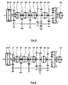
- Fig. 1 shows a powershift transmission 1 with a dual clutch 2 with two clutches K1 and K2, a split group 3, a main group 4 and a range group. 5
- the splitter group 3 has two input shafts 6, 7 which can be brought into drive connection with a transmission input shaft 8 selectively via the clutches K1, K2 or with the use of an overlap control.
- a drive of a countershaft 12 with different ratios is possible via input constants E1, E2 and E3 with assigned gear levels.
- the input constants E1, E2, E3 have drive-side gears 13 to 15, which are in constant meshing connection with output-side gears 16 to 18 of the input constants E1, E2 and E3.
- the gears 13 to 15 are designed as loose wheels, wherein the gear 13 is rotatably mounted relative to the input shaft 7, while the gears 14, 15 are rotatably mounted relative to the input shaft 6.
- the input shaft 7 is formed as a hollow shaft and surrounds the input shaft 6 with the interposition of a storage.
- a switching element S2 connects in a switching position S2 (E2) rotatably the gear 14 with the input shaft 6 and in a switching position S2 (E3), the gear 15 rotatably with the input shaft 6, while in the sketched central neutral position of the switching element S2 no connection of the gears 13, 14 is given to the input shaft 6 via the switching element S2.
- the countershaft 12 carries drive-side gears 19, 20, 21, which constantly mesh with output-side gears 22, 23, 24 in toothing planes H1, HR, H2, wherein between the gears 20 and 23, a reverse gear 25 is interposed ,
- the gears 22-24 are each mounted as loose wheels relative to a main shaft 26 of the main group 4, which in turn is mounted via a pilot bearing relative to the input shaft 6.
- the switching element S3 By means of a switching element S3, the main shaft 26 in a left shift position S3 (1) rotatably connected to the input shaft 6 and in a right shift position S3 (H1) rotatably connected to the gear 22, while in the sketched central neutral position, the switching element S3 is ineffective.
- a in the sketched central neutral position inactive switching element S4 connects in a switching position S4 (HR) the gear 23 to the main shaft 26, while in a switching position S4 (H2) a rotationally fixed connection between the gear 24 and main shaft 26 is provided.
- the range group has gear elements in the form of a rotatably connected to the main shaft 26 sun gear 27, of planets 28 which are rotatably supported by a web 29, and a ring gear 30, by means of which in known manner, a planetary gear 31 is formed.
- the jetty 29 is rotatably connected to an output shaft 32 or transmission output shaft.
- a switching element S5 is ineffective in the illustrated central neutral position, while this in a left shift position S5 (1) the ring gear 30 rotatably connected to the housing or brakes against this, while in a right shift position S5 (2) the ring gear 30 rotatably connected to the output shaft 32 is connected so that the planetary gear set 31 rotates in the block.
- Table 1 shows for the gears 1 to 18 and the reverse gears R1 to R6, the clutch and switching states for the clutches K2, K1 and the switching elements S1 to S5, with three corners, the respective closed clutch is indicated, while with filled circles the switching position of the switching elements is indicated, which are effective and are marked with empty circles switching elements, which are in a neutral position.
- Table 1 is characterized by the combination of groups of lines and by the division by the double strokes, which gears are sequentially switchable and traction interruption free, namely gears 1 to 3, gears 4 to 8, gears 10 to 12, gears 13 to 17.
- the power flow in the individual gears shows Fig. 2 , from which it can be seen that the 16th gear is designed as a direct gear, in which the power flow through the transmission input shaft 8, clutch K2, input shaft 6, switching element S3, main shaft 26 extends over the blocked planetary gear set 31 to the output shaft 32.
- a similar direct transmission of the drive torque takes place in the 7th gear in the split group 3 and the main group 4, in which case the switching element S5 is in the switching position S5 (1), so that the planetary gear set 31 a translation i> 1 causes.
- the input constants E2, E3, E1 are used in the above order, in the gears 1 to 3 in the main group 4 gear level H1 is used in the Gear ratios 4 to 6 gear level H2, in gear ratios 10 to 12 gear level H1 and in gear ratios 13 to 15 gear level H2.
- gear ratios 8 and 9 as well as 17 and 18, no powers are transmitted via the gear levels H1, HR, H2, since the power is returned in the range of the input constants E2 (gears 9, 18) and the input constants E3 (gears 8, 17) , each preceded by the input constant E1.
- the gears 17 and 18 form overdrive gears with a total ratio of i ⁇ 1. Between the two overdrive gears 17 and 18 can not be switched without traction interruption. However, an action on the overdrive gear 18 of the direct gear 16 from without interruption of traction possible.
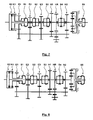
- Fig. 3 shows the gearbox for an activated 12th gear.
- this runs the power flow through the clutch K1, switching element S1 in shift position S1 (E1), gears 13, 16, countershaft 12, gears 19, 22, switching element S3 in Shift position S3 (H1) main shaft 26 and as a result of switching element S5 in shift position S5 (2) interlocked planetary gear set 31 to the output shaft 32nd
- the torque is then transferred from the clutch K1 to the clutch K2, so that the power flow from the transmission input shaft 8 via the clutch K2, shift element S2 in shift position S2 (E2), gears 14, 17, countershaft 12, gears 19, 22, switching element S3 in shift position S3 (H1), main shaft 26 and the blocked planetary gear set 31 runs ( Fig. 5 ).
- Fig. 6 is subsequently the gear 13 of the input constant E1 decoupled from the input shaft 7 in that the switching element S1 is moved from the switching position S1 (E1) in the neutral position.
- the gear 14 is coupled to the transmission shaft 7 in that the switching element S1 and the switching position S1 (E2) is spent.
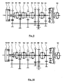
- FIG. 12 An activation of the 11th gear is done according to Fig. 12 by transferring the drive torque from the clutch K1 to the clutch K2.
- the in Fig. 12 shown switching state corresponds to the specified in Table 1 for the gear 11 switching state.
- the gear 14 of the input constant E2 must be rotatably connected to the input shaft 6 starting from the gear 10, which is the case in the switching position S2 (E2).
- the gear 14 is also connected via the switching element S1 in the switching position S1 (E2) to the input shaft 7.
- this connection is achieved in which the gear 14 is decoupled from the input shaft 7 by transferring the switching element S1 to the position S1 (N).
- This is followed by a connection of the gear 13 with the input shaft 7 in that the switching element S1 is transferred to the switching position S1 (E1).
- the double upshift is complete as soon as clutch K2 is fully opened and clutch K1 is completely closed.
- a shift strategy can be used in which the gear 14 of the input constant E2 is connected in advance to the input shaft 6, so that the previous described "change" of the rotationally fixed connection from the input shaft 6 to the input shaft 7 in the need of Mehrfachrochscnies can be avoided.
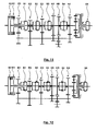
- Fig. 13 shows a further embodiment of the transmission 1a according to the invention, which substantially the transmission 1 according to the FIGS. 1 to 12 equivalent.
- an additional countershaft 12a is provided, which is arranged with respect to the rolling connections and on the countershaft 12a Gears of the countershaft 12 corresponds.
- Fig. 14 shows at otherwise Fig. 13 corresponding configuration of the transmission 1b, an arrangement of a countershaft brake 33 via which the speed of the countershaft 12 is variable for synchronization during a switching operation at at least partially unsynchronized switching elements.
- a transmission with 20 forward gears possible In an additional 7th gear and an additional 17th gear, a combination of the input constants E2 and E3 to form a translation with i> 1 can be used. Deviating from the embodiments according to Fig. 1 to 14 In this case, a top group of power-shiftable adjacent gears no longer comprises 5 gears, but only 3 gears.
- the input shafts 6, 7 are designed to be comparatively long for the exemplary embodiments shown, whereby due to the meshing of the input constants E1, E2, E3 relatively large radial forces and thus caused moments can be effected, which can be absorbed by additional bearings of the input shafts 6, 7.
- Another additional or alternative remedy is the described division and mutual compensation of forces and moments by using two countershafts 12, 12a according to Fig. 13 possible.
Landscapes
- Engineering & Computer Science (AREA)
- General Engineering & Computer Science (AREA)
- Mechanical Engineering (AREA)
- Structure Of Transmissions (AREA)
Description
Die Erfindung betrifft ein lastschaltbares Getriebe für ein Nutzfahrzeug mit einer Splitgruppe, einer Hauptgruppe und einer Rangegruppe.The invention relates to a power shift transmission for a commercial vehicle with a split group, a main group and a range group.
Aus der nicht vorveröffentlichten Anmeldung der Anmelderin mit dem internen Aktenzeichen P807553/DE/1 und dem Titel "Lastschaltbares Gruppengetriebe" ist ein Getriebe für ein Nutzfahrzeug bekannt, welches eine Splitgruppe, eine Hauptgruppe und eine Rangegruppe aufweist und 12, 16 oder 20 Vorwärtsgänge besitzt. Auch zur Gewährleistung einer Leistungsverzweigung in einzelnen Getriebegängen treiben die mit der Doppelkupplung verbundenen Eingangswellen jeweils über eine Eingangskonstante zwei koaxial zueinander angeordnete Vorgelegewellen an.From the not previously published application of the applicant with the internal file number P807553 / DE / 1 and the title "Lastschaltbares group transmission" a transmission for a commercial vehicle is known, which has a split group, a main group and a range group and has 12, 16 or 20 forward gears. Also, to ensure a power split in individual transmission gears connected to the dual clutch input shafts each drive via an input constant to two coaxially arranged countershafts.
Aus der nicht vorveröffentlichten Anmeldung der Anmelderin mit dem internen Aktenzeichen der Anmelderin P807447/DE/1 mit dem Titel "Automatisiertes Lastschaltgetriebe" ist ein Getriebe für ein Nutzfahrzeug bekannt mit einer Splitgruppe, einer Hauptgruppe und einer Rangegruppe, wobei in diesem Fall mit Ausnahme eines eventuell vorhandenen Direktgangs die Leistungspfade in sämtlichen Vorwärts-Getriebegängen über dieselbe Vorgelegewelle verlaufen. Im Umgebungsbereich eines Direktgangs sind bis zu vier sequentiell lastschaltbare Getriebegänge möglich. Die Eingangskonstanten sind selektiv jeweils mit einer zugeordneten Eingangswelle und Kupplung der Doppelkupplung verbindbar. Mehrfach Hoch- und Rückschaltungen sowie eine Übergabe eines Antriebsmomentes von einer Kupplung auf eine andere Kupplung für denselben Getriebegang sind in dieser Druckschrift nicht angesprochen.From the unpublished application of the applicant with the internal file number of the Applicant P807447 / DE / 1 entitled "Automated powershift transmission" a transmission for a commercial vehicle is known with a split group, a main group and a range group, in which case with the exception of one existing direct gear the power paths in all forward gears pass over the same countershaft. In the vicinity of a direct gear, up to four sequentially power-shiftable gearings are possible. The input constants are selectively connectable to an associated input shaft and clutch of the dual clutch. Multiple upshifts and downshifts and a transfer of a drive torque from one clutch to another clutch for the same gear are not addressed in this document.
Weitere Getriebe, bei denen Eingangskonstanten jeweils einer einzelnen Kupplung einer Doppelkupplung zugeordnet sind und je nach beaufschlagter Kupplung der Leistungspfad über eine von zwei koaxialen Vorgelegewellen verläuft, sind aus
Der vorliegenden Erfindung liegt die Aufgabe zugrunde, ein für ein Nutzfahrzeug einsetzbares lastschaltbares Getriebe vorzuschlagen, welches hinsichtlich des konstruktiven Aufwands, insbesondere der einzusetzenden Schaltelemente, der Lagerungen und des Bauraumes, der sequentiellen Lastschaltbarkeit, bei gleichzeitiger Ermöglichung von Mehrfachhochschaltungen oder Mehrfachrückschaltungen ohne Zugkraftunterbrechung verbessert ist.The present invention has for its object to provide a usable for a commercial vehicle powershift transmission, which is improved in terms of design effort, in particular the switching elements to be used, the bearings and the installation space, the sequential powershifting, while enabling multiple upshifts or multiple downshifts without interruption of traction.
Die der Erfindung zugrunde liegende Aufgabe wird gelöst durch ein lastschaltbares Getriebe gemäß den Merkmalen des Anspruchs 1.The object underlying the invention is achieved by a power shift transmission according to the features of
Ein derartiges Getriebe zeichnet sich zunächst durch Hintereinanderschaltung einer Splitgruppe, einer Hauptgruppe und einer Rangegruppe aus, wodurch eine hohe Variabilität der möglichen Getriebegänge unter vertretbaren Bauaufwand gegeben ist, über die auch schwere Nutzfahrzeuge mit variierenden Fahrbedingungen feinstufig antreibbar sind.Such a transmission is initially characterized by the series connection of a split group, a main group and a range group, whereby a high variability of the possible gears is given under reasonable construction costs, over which even heavy commercial vehicles with varying driving conditions are finely driven.
Weiterhin sind selektiv über die Doppelkupplung antreibbare Eingangswellen koaxial zu einer Abtriebswelle des Getriebes angeordnet, wodurch sich eine gute Integration in einen Antriebsstrang eines Nutzfahrzeuges ergibt.Furthermore, selectively driven via the double clutch input shafts coaxial with an output shaft of the transmission, resulting in a good integration into a drive train of a commercial vehicle results.
Die vorliegende Erfindung baut auf dem Grundgedanken gemäß
Weiterhin kann durch die selektive Verbindbarkeit des Losrades ermöglicht werden, dass ein Getriebegang und ein Wechsel in diesen wahlweise über eine der beiden Kupplungen erfolgen kann. Somit kann erfindungsgemäß beispielsweise mit einer geeigneten Steuerung einer Überlastung einer Kupplung, beispielsweise während eines Anfahrvorgangs, einem unterschiedlichen Verschleiß der Kupplungen und etwaigen Beeinträchtigungen einer Kupplung, Rechnung getragen werden. Dies kann auch zu einer Verlängerung von Wartungsintervallen führen.Furthermore, it can be made possible by the selective connectivity of the idler gear that a gear and a change in these can be done either via one of the two clutches. Thus, according to the invention, for example, with a suitable control of an overload of a clutch, for example during a start-up, a different wear of the clutches and any impairments of a clutch, bill be taken into account. This can also lead to an extension of maintenance intervals.
Erfindungsgemäß ist eine der beiden Eingangswellen über ein Schaltelement drehfest mit einer Hauptwelle der Hauptgruppe verbindbar, so dass ein direkter Durchtrieb durch Splitgruppe und Hauptgruppe mit einem optimalen Wirkungsgrad erfolgt. Durch Nachschaltung einer Rangegruppe kann ein derart vorteilhafter Betrieb für eine Mehrzahl unterschiedlicher Getriebegänge je nach Schaltzustand der Rangegruppe genutzt werden. Hierbei ist von besonderem Vorteil, dass die Rangegruppe ebenfalls einen Direktgang aufweist, in dem in den Leistungsfluss in der Rangegruppe keine wälzenden Zahnräder zwischengeschaltet sind. Damit besitzt das Gesamtgetriebe Getriebegänge mit gutem Wirkungsgrad, in denen ein direkter Durchtrieb durch die Splitgruppe und Hauptgruppe erfolgt, sowie einen Getriebegang mit weiter verbessertem Wirkungsgrad, in dem ein Direktgang durch Splitgruppe, Hauptgruppe und Rangegruppe gegeben ist.According to the invention, one of the two input shafts can be connected in a rotationally fixed manner to a main shaft of the main group via a switching element, so that a direct drive through split group and main group takes place with an optimum efficiency. By connecting a range group, such an advantageous operation can be used for a plurality of different transmission gears depending on the switching state of the range group. It is of particular advantage that the range group also has a direct gear, in which no rolling gears are interposed in the power flow in the range group. Thus, the overall transmission has gears with good efficiency, in which a direct drive through the split group and main group takes place, and a gear with further improved efficiency, in which a direct course is given by split group, main group and range group.
Während gemäß
Weitere Vorteile hinsichtlich des Bauaufwands ergeben sich infolge der erfindungsgemäß geschaffenen Möglichkeit, dass die der oder einer Vorgelegewelle zugeordneten Zahnräder sämtlich als Festräder ausgebildet sein können, wodurch Schaltelemente und zusätzlicher Bauraum im Bereich der Vorgelegewelle eingespart werden können. Weiterhin ist unter Umständen eine Betätigung der Schaltelemente sämtlich im Bereich der gemeinsamen Achse der Eingangswellen und der Abtriebswelle möglich, wodurch kompakte, "zentralisierte" Aktuatoren und elektrische Steuereinheiten für diese möglich sind.Further advantages in terms of construction costs arise as a result of inventively created possibility that the or a countershaft associated gears may all be formed as fixed wheels, whereby switching elements and additional space in the countershaft can be saved. Furthermore, under certain circumstances, an actuation of the switching elements is all possible in the region of the common axis of the input shafts and the output shaft, whereby compact, "centralized" actuators and electrical control units for this are possible.
Trotz eines Verzichts auf die Ausbildung des Getriebes mit zwei Teilgetrieben gemäß P807553/DE/1 können die in dieser nicht vorveröffentlichten Anmeldung beschriebenen Vorteile erzielt werden, insbesondere Doppelrück- oder Doppelhochschaltungen ohne Unterbrechung der Zugkraft sowie auch Dreifachrück- oder Dreifachhochschaltungen realisiert werden. Andererseits ist gemäß P807447/DE/1 ein Verlauf sämtlicher Getriebegänge ausschließlich eines Direktgangs über eine einzige Vorgelegewelle bekannt - für diese bekannte Ausgestaltung ist jedoch nicht der Antrieb einer Eingangskonstanten von beiden Kupplungen und Eingangswellen möglich, wodurch sich eine verringerte Variabilität insbesondere hinsichtlich zugkraftunterbrechungsfreier Mehrfachhochschaltungen und Mehrfachrückschaltungen ergibt.Despite a waiver of the design of the transmission with two partial transmissions according to P807553 / DE / 1 the advantages described in this non-prepublished application can be achieved, in particular Doppelrück- or double upshifts without interruption of the traction and also Dreifachrück- or triple upshifts can be realized. On the other hand, according to P807447 / DE / 1 a course of all gears exclusively a direct gear on a single countershaft known - for this known embodiment, however, is not the drive of an input constant of both clutches and input shafts possible, resulting in a reduced variability in particular with regard to traction interruption-free Mehrfachhochschaltungen and multiple downshifts results.
In besonders vorteilhafter Weise können sämtliche Schaltelemente bzw. -muffen so angeordnet sein, dass diese ausschließlich koaxial zu den Eingangswellen angeordnet sind. In diesem Fall kann die Aktuatorik zur Betätigung der Schaltelemente besonders kompakt und kostengünstig ausgeführt sein. In diesem Fall kann ausschließlich eine Vorgelegewelle vorgesehen sein, die dann ausschließlich Festräder trägt. Eine derartige Verwendung einer einzigen Vorgelegewelle hat Kosten-, Gewichts- und Bauraumvorteile, die den Nachteil einer hohen Wellendurchbiegung und hohen Lagerkräften entgegenstehen, da die Verzahnungskräfte an den Kraft übertragenden Verzahnungen bestrebt sind, die beiden parallel beabstandeten Wellen voneinander weg zu drücken. Eine derartige hohe Wellendurchbiegung kann beispielsweise mittels Einsatzes einer Wälzlagerung gemäß
Gemäß einem weiteren Vorschlag der Erfindung sind die eingangsseitigen Zahnräder der Eingangskonstanten nicht lediglich zur Übergabe der Antriebsbewegung auf die Vorgelegewelle genutzt. Vielmehr wird über eine erste Eingangskonstante das Antriebsmoment zunächst von einer Eingangswelle zu der Vorgelegewelle übertragen. In dieser ersten Eingangskonstanten ist das selektiv mit beiden Eingangswellen verbindbare Losrad wirksam. Über eine weitere "Eingangskonstante" wird in "umgekehrtem" Leistungsfluss die Leistung von der Vorgelegewelle zu der anderen Eingangswelle zurückgeführt, die über ein Schaltelement drehfest mit der Hauptwelle des Hauptgetriebes verbunden ist. Für diesen Getriebegang sind damit Zahnradpaare der Hauptgruppe nicht genutzt.According to a further proposal of the invention, the input-side gears of the input constants are not used only for transferring the drive movement to the countershaft. Rather, the drive torque is first transmitted from an input shaft to the countershaft via a first input constant transfer. In this first input constant, the idler gear which can be selectively connected to both input shafts is effective. Via a further "input constant", the power is fed back from the countershaft to the other input shaft, which is connected in a rotationally fixed manner to the main shaft of the main gear in a "reverse" power flow. Gear pairs of the main group are thus not used for this gear.
Eine besonders kompakte Ausgestaltung des Getriebes ergibt sich in dem Fall, wenn die Verbindung zwischen Eingangswelle (oder zugeordnetem Zahnrad für die Leistungsrückführung) und der Hauptwelle der Hauptgruppe über das Schaltelement hergestellt wird, welches auch in dem Direktgang eine Verbindung der Eingangswelle mit der Hauptwelle herbeiführt.A particularly compact design of the transmission results in the case when the connection between the input shaft (or associated gear for power return) and the main shaft of the main group is made via the switching element, which causes a connection of the input shaft to the main shaft in the direct gear.
Die in den nicht vorveröffentlichten Anmeldungen P807447 und P807553 beschriebenen Vorteile können erfindungsgemäß ebenfalls genutzt werden, wenn Gruppen von Getriebegängen sequentiell schaltbar sind.The advantages described in the non-prepublished applications P807447 and P807553 can also be used according to the invention when groups of gears are sequentially switchable.
Ein verbesserter Komfort und eine verbesserte Leistungscharakteristik ergeben sich, wenn zugkraftunterbrechungsfreie Doppelhoch- oder Doppelrückschaltungen oder Mehrfachhochschaltungen oder Mehrfachrückschaltungen möglich sind, über die der Schaltzustand des Getriebes noch individueller an die jeweiligen Fahrbedingungen anpassbar sind.An improved comfort and an improved performance result when traction interruption-free double-up or double-downshifts or multiple upshifts or multiple downshifts are possible over which the switching state of the transmission are even more individually adaptable to the respective driving conditions.
Während üblicherweise benachbarte Gänge jeweils über unterschiedliche Kupplungen aktivierbar und deaktivierbar sind, was zur Folge hat, dass um eine Zahl 2 verschiedene Getriebegänge über dieselbe Kupplungen aktiviert werden, ist durch die selektive Verbindbarkeit des Losrades mit beiden Kupplungen die Möglichkeit gegeben, bei einer Doppelhoch- oder Doppelrückschaltung beide Kupplungen zu verwenden, wodurch diese erst zugkraftunterbrechungsfrei gestaltet werden können. Soll nach einer derartigen Doppelhoch- oder Doppelrückschaltung ein sequentieller Schaltvorgang zu einem benachbarten Getriebegang erfolgen, kann sich das Problem ergeben, dass dieser benachbarte Getriebegang über die für die Doppelhoch- oder Doppelrückschaltung genutzte Kupplung erfolgen muss. Hierzu schlägt die Erfindung vor, dass in einem derartigen Fall eine Übergabe von einer Kupplung der Doppelkupplung und der hiermit verbundenen Eingangswelle auf die andere Kupplung der Doppelkupplung und die hiermit verbundene Eingangswelle zur Vorbereitung der sequentiellen Schaltung erfolgt. Somit kann sowohl die Doppelhoch- oder Doppelrückschaltung als auch eine anschließende sequentielle Schaltung zugkraftunterbrechungsfrei gestaltet werden.While usually adjacent gears can be activated and deactivated in each case via different clutches, which has the consequence that a
Erfindungsgemäß kann eine weitere Verbesserung des Wirkungsgrades dadurch erzielt werden, dass in dem Direktgang ein Teil oder sämtliche Eingangskonstanten nicht in Antriebsverbindung mit den Eingangswellen stehen. Hierdurch können eine Lagerreibung, etwaige Planschverluste und die in dem Direktgang bewegte träge Masse reduziert werden. Besonders vorteilhaft ist hierbei, wenn die Eingangskonstanten eingangsseitige Zahnräder aufweisen, die Losräder auf den Eingangswellen darstellen und somit in dem Direktgang von den Eingangswellen entkoppelbar sind.According to the invention, a further improvement of the efficiency can be achieved in that in the direct gear part or all of the input constants are not in drive connection with the input shafts. As a result, a bearing friction, any splashing losses and moving in the direct gear inertial mass can be reduced. In this case, it is particularly advantageous if the input constants have input-side gears, which represent idler gears on the input shafts and thus can be decoupled from the input shafts in the direct gear.
Für die Gestaltung des Getriebes für maximale Fahrgeschwindigkeiten kann es von Vorteil sein, wenn zumindest ein Overdrive-Getriebegang (Übersetzung i<1) vorgesehen ist. Ein vergrößerter Fahrkomfort ergibt sich in diesem Fall, wenn der Schaltvorgang von dem Direktgang zu dem mindestens einen Overdrive-Getriebegang (und umgekehrt) zugkraftunterbrechungsfrei möglich ist.For the design of the transmission for maximum travel speeds, it may be advantageous if at least one overdrive transmission gear ratio (ratio i <1) is provided. An increased ride comfort results in this case, when the switching operation of the direct gear to the at least one overdrive gear (and vice versa) traction interruption-free is possible.
Gemäß einer erfindungsgemäßen Weiterbildung des lastschaltbaren Getriebes ist die Rangegruppe als Planetengetriebe ausgebildet, die sich durch einfache koaxiale Gestaltung, geringen radialen Bauraum, günstige Drehmomenten- und Drehzahlverhältnisse auszeichnet. Ein Direktgang kann für ein derartiges Planetengetriebe dadurch ausgebildet werden, dass in einem derartigen Direktgang das Planetengetriebe im Block umläuft. Ein anderer Schaltzustand des Planetengetriebes kann beispielsweise in einem gegenüber dem Gehäuse gebremsten Getriebeelement des Planetengetriebes, beispielsweise in einem gebremsten Hohlrad, bestehen.According to a development of the power shift transmission according to the invention, the range group is designed as a planetary gear, which is characterized by simple coaxial design, low radial space, favorable torque and speed ratios. A direct gear can be for such a Planetary gear can be formed by the fact that in such a direct gear, the planetary gear rotates in the block. Another switching state of the planetary gear, for example, in a braked with respect to the housing gear element of the planetary gear, for example, in a braked ring, consist.
Der Fahrkomfort des lastschaltbaren Getriebes kann erfindungsgemäß dadurch weiter erhöht werden, dass eine oberste Gruppe sequentiell lastschaltbarer Getriebegänge fünf Getriebegänge umfasst, für die damit komfortabel bei großen Geschwindigkeiten der Schaltzustand des Getriebes an die Betriebsbedingungen anpassbar ist.The ride comfort of the powershift transmission can be further increased according to the invention in that a top group of sequentially powershift transmission gears comprises five gears for which thus comfortable at high speeds, the switching state of the transmission to the operating conditions is customizable.
Zur Reduzierung des Bauaufwandes für einzelne oder sämtliche Schaltelemente schlägt die Erfindung vor, zumindest ein Schaltelement als unsynchronisiertes Schaltelement auszubilden. In einem derartigen Fall kann eine Synchronisierung eines oder mehrerer Schaltelemente in einzelnen oder mehreren Getriebegängen über eine zentrale Synchronisiereinrichtung erfolgen, bei der es sich um eine zentrale Bremse oder ein Antriebsaggregat für Zahnräder oder Getriebewellen handeln kann.To reduce the construction costs for individual or all switching elements, the invention proposes to form at least one switching element as an unsynchronized switching element. In such a case, a synchronization of one or more switching elements in single or multiple gears can be done via a central synchronizer, which may be a central brake or a drive unit for gears or transmission shafts.
In besonderer Ausgestaltung des lastschaltbaren erfindungsgemäßen Getriebes ist eine derartige zentrale Synchronisiereinrichtung als Vorgelegewellenbremse ausgebildet.In a particular embodiment of the power shift transmission according to the invention such a central synchronizer is designed as a countershaft brake.
Vorteilhafte Weiterbildungen ergeben sich aus den Unteransprüchen, der Beschreibung und den Zeichnungen. Weitere Merkmale sind der Zeichnung, insbesondere den dargestellten Geometrien der Bauteile, den relativen Abmessungen mehrerer dargestellter Maße gleicher oder unterschiedlicher Bauteile, der relativen Anordnung der Bauteile zueinander und deren Wirkverbindungen miteinander, zu entnehmen. Die Kombination von Merkmalen unterschiedlicher in verschiedenen Figuren dargestellter Ausgestaltungen, Merkmalen unterschiedlicher Ansprüche und/oder der vorgenannten Merkmale mit Merkmalen der Ausgestaltungen des genannten Standes der Technik ist ebenfalls möglich und wird hiermit angeregt.Advantageous developments emerge from the subclaims, the description and the drawings. Further features of the drawing, in particular the illustrated geometries of the components, the relative dimensions of several illustrated dimensions of the same or different components, the relative arrangement of the components to each other and their operative connections with each other, refer. The combination of features of different embodiments shown in different figures, features different claims and / or the aforementioned features with features of the embodiments of said prior art is also possible and is hereby stimulated.
Ein bevorzugtes Ausführungsbeispiel der erfindungsgemäßen Vorrichtung wird nachfolgend anhand der Zeichnung näher erläutert. In der Zeichnung zeigt:
- Fig. 1
- einen Räderplan eines erfindungsgemäßen last- schaltbaren Getriebes für
ein Nutzfahrzeug mit 18 oder 20 Vorwärtsgängen, - Fig. 2
- den Leistungsfluss in 18 Vorwärtsgängen für das Getriebe gemäß
Fig. 1 , - Fig. 3 - 12
- die Abfolge der Schaltzustände der Schaltele- mente des Getriebes gemäß
Fig. 1 für eine Doppelrückschaltung von einem 12. Getriebe-gang zu einem 10. Getriebegang mit anschlie- ßender sequentiellerLastschaltung von dem 10. Getriebegang ineinen 11. Getriebegang, - Fig. 13
- eine alternative Ausgestaltung eines Räder- plans für ein erfindungsgemäßes lastschaltba- res Getriebe, bei dem der Leistungsfluss auf zwei im Wesentlichen übereinstimmend ausge- bildete Vorgelegewellen aufgeteilt wird,
- Fig. 14
- eine alternative Ausgestaltung eines Räder- plans eines erfindungsgemäßen lastschaltbaren Getriebes mit einer Vorgelegewellenbremse zur Synchronisierung bei Schaltvorgängen und
- Fig. 15
- die Leistungsflüsse für das in
Fig. 1 darge- stellte Ausführungsbeispiel eines lastschalt- baren Getriebes beiEinsatz von 20 Vorwärts- Getriebegängen.
- Fig. 1
- a wheel plan of a load-shiftable transmission according to the invention for a commercial vehicle with 18 or 20 forward gears,
- Fig. 2
- the power flow in 18 forward gears for the transmission according to
Fig. 1 . - Fig. 3 - 12
- the sequence of switching states of the Schaltele- elements of the transmission according to
Fig. 1 for a double downshift from a 12th gear to a 10th gear with subsequent sequential load shifting from the 10th gear to an 11th gear, - Fig. 13
- an alternative embodiment of a wheel plan for a power-shiftable transmission according to the invention, in which the power flow is divided into two substantially matching countershafts,
- Fig. 14
- an alternative embodiment of a wheels plan of a power shift transmission according to the invention with a countershaft brake for synchronization in switching operations and
- Fig. 15
- the power flows for the in
Fig. 1 illustrated embodiment of a power shift Baren gearbox when using 20 forward gears.
Die Splitgruppe 3 besitzt zwei Eingangswellen 6, 7, die über die Kupplungen K1, K2 selektiv oder mit Einsatz einer Überschneidungssteuerung in Antriebsverbindung mit einer Getriebeeingangswelle 8 bringbar sind. In der Splitgruppe 3 ist über Eingangskonstanten E1, E2 und E3 mit zugeordneten Zahnradebenen ein Antrieb einer Vorgelegewelle 12 mit unterschiedlichen Übersetzungen möglich. Die Eingangskonstanten E1, E2, E3 besitzen antriebsseitige Zahnräder 13 bis 15, die in ständig kämmender Verbindung mit abtriebsseitigen Zahnrädern 16 bis 18 der Eingangskonstanten E1, E2 und E3 stehen. Die Zahnräder 13 bis 15 sind als Losräder ausgeführt, wobei das Zahnrad 13 drehbar gegenüber der Eingangswelle 7 gelagert ist, während die Zahnräder 14, 15 drehbar gegenüber der Eingangswelle 6 gelagert sind. Die Eingangswelle 7 ist als Hohlwelle ausgebildet und umgibt die Eingangswelle 6 unter Zwischenschaltung einer Lagerung.The
Über ein Schaltelement S1 ist die Eingangswelle 7 in einer Schaltstellung S1 (E1) drehfest mit dem Zahnrad 13 verbindbar sowie in einer Schaltstellung S1 (E2) drehfest mit dem Zahnrad 14 verbindbar, während in der dargestellten mittigen Neutralstellung über das Schaltelement S1 keine Verbindung zwischen den Zahnrädern 13, 14 und der Eingangswelle 7 geschaffen ist.About a switching element S1, the
Ein Schaltelement S2 verbindet in einer Schaltstellung S2 (E2) drehfest das Zahnrad 14 mit der Eingangswelle 6 und in einer Schaltstellung S2 (E3) das Zahnrad 15 drehfest mit der Eingangswelle 6, während in der skizzierten mittigen Neutralstellung des Schaltelements S2 keine Verbindung der Zahnräder 13, 14 mit der Eingangswelle 6 über das Schaltelement S2 gegeben ist.A switching element S2 connects in a switching position S2 (E2) rotatably the
Im Bereich der Hauptgruppe 4 trägt die Vorgelegewelle 12 antriebsseitige Zahnräder 19, 20, 21, die ständig mit abtriebsseitigen Zahnrädern 22, 23, 24 in Verzahnungsebenen H1, HR, H2 kämmen, wobei zwischen die Zahnräder 20 und 23 ein Rückwärtsgang-Zahnrad 25 zwischengeschaltet ist. Die Zahnräder 22-24 sind jeweils als Losräder gegenüber einer Hauptwelle 26 der Hauptgruppe 4 gelagert, die wiederum über eine Pilotlagerung gegenüber der Eingangswelle 6 gelagert ist.In the area of the
Mittels eines Schaltelements S3 ist die Hauptwelle 26 in einer linken Schaltstellung S3 (1) mit der Eingangswelle 6 drehfest verbindbar sowie in einer rechten Schaltstellung S3 (H1) drehfest mit dem Zahnrad 22 verbindbar, während in der skizzierten mittigen Neutralstellung das Schaltelement S3 unwirksam ist.By means of a switching element S3, the
Ein in der skizzierten mittigen Neutralstellung unwirksames Schaltelement S4 verbindet in einer Schaltstellung S4 (HR) das Zahnrad 23 mit der Hauptwelle 26, während in einer Schaltstellung S4 (H2) eine drehfeste Verbindung zwischen Zahnrad 24 und Hauptwelle 26 geschaffen ist.A in the sketched central neutral position inactive switching element S4 connects in a switching position S4 (HR) the
Die Rangegruppe besitzt Getriebeelemente in Form eines drehfest mit der Hauptwelle 26 verbundenen Sonnenrades 27, von Planeten 28, die über einen Steg 29 drehbar gelagert sind, sowie eines Hohlrades 30, mittels welchen auf an sich bekannte Weise ein Planetengetriebe 31 gebildet ist. Der Steg 29 ist drehfest mit einer Abtriebswelle 32 oder Getriebeausgangswelle verbunden.The range group has gear elements in the form of a rotatably connected to the
Ein Schaltelement S5 ist in der dargestellten mittigen Neutralstellung wirkungslos, während dieses in einer linken Schaltstellung S5(1) das Hohlrad 30 drehfest mit dem Gehäuse verbindet oder gegenüber diesem bremst, während in einer rechten Schaltstellung S5(2) das Hohlrad 30 drehfest mit der Abtriebswelle 32 verbunden ist, so dass der Planetensatz 31 im Block umläuft.A switching element S5 is ineffective in the illustrated central neutral position, while this in a left shift position S5 (1) the
Die folgende Tabelle 1 zeigt für die Getriebegänge 1 bis 18 sowie die Rückwärts-Getriebegänge R1 bis R6 die Kupplungs- und Schaltzustände für die Kupplungen K2, K1 und die Schaltelemente S1 bis S5, wobei mit drei Ecken die jeweils geschlossene Kupplung indiziert ist, während mit ausgefüllten Kreisen die Schaltstellung der Schaltelemente indiziert ist, die wirksam sind und mit leeren Kreisen Schaltelemente gekennzeichnet sind, die sich in einer Neutralstellung befinden.
Darüber hinaus ist Tabelle 1 durch die Zusammenfassung von Gruppen von Zeilen und durch die Trennung durch die Doppelstriche gekennzeichnet, welche Getriebegänge sequentiell und zugkraftunterbrechungsfrei schaltbar sind, nämlich Getriebegänge 1 bis 3, Getriebegänge 4 bis 8, Getriebegänge 10 bis 12, Getriebegänge 13 bis 17.In addition, Table 1 is characterized by the combination of groups of lines and by the division by the double strokes, which gears are sequentially switchable and traction interruption free, namely gears 1 to 3, gears 4 to 8, gears 10 to 12, gears 13 to 17.
Den Leistungsfluss in den einzelnen Getriebegängen zeigt
Für die Getriebegänge 1 bis 3 sowie 4 bis 6 sowie 10 bis 12 sowie 13 bis 15 finden die Eingangskonstanten E2, E3, E1 in der vorgenannten Reihenfolge Einsatz, wobei in den Getriebegängen 1 bis 3 in der Hauptgruppe 4 Zahnradebene H1 Einsatz findet, in den Getriebegängen 4 bis 6 Zahnradebene H2, in Getriebegängen 10 bis 12 Zahnradebene H1 und in Getriebegängen 13 bis 15 Zahnradebene H2. In den Getriebegängen 8 und 9 sowie 17 und 18 wird über die Zahnradebenen H1, HR, H2 keine Leistungen übertragen, da eine Rückführung der Leistung im Bereich der Eingangskonstanten E2 (Getriebegänge 9, 18) und der Eingangskonstanten E3 (Getriebegänge 8, 17) erfolgt, jeweils unter Vorschaltung der Eingangskonstanten E1.For the
An dem rechten Rand der
Die Getriebegänge 17 und 18 bilden Overdrive-Getriebegänge mit einer Gesamtübersetzung von i<1. Zwischen den beiden Overdrive-Getriebegängen 17 und 18 kann nicht ohne Zugkraftunterbrechung geschaltet werden. Allerdings ist eine Beaufschlagung des Overdrive-Getriebeganges 18 von dem Direktgang 16 aus ohne Zugkraftunterbrechung möglich.The
Für eine Doppelrückschaltung aus dem Getriebegang 12 zum Getriebegang 10 wird zunächst das Zahnrad 14 über Schaltelement S2, welches in die Schaltstellung S2(E2) verbracht wird, mit der Eingangswelle 6 verbunden, ohne dass die Kupplung K2 geschlossen ist, siehe
Durch geeignete Überschneidungssteuerung wird dann das Moment von der Kupplung K1 auf die Kupplung K2 übergeben, so dass der Leistungsfluss von der Getriebeeingangswelle 8 über die Kupplung K2, Schaltelement S2 in Schaltstellung S2(E2), Zahnräder 14, 17, Vorgelegewelle 12, Zahnräder 19, 22, Schaltelement S3 in Schaltstellung S3 (H1), Hauptwelle 26 und den geblockten Planetensatz 31 verläuft (
Gemäß
Gemäß
Mittels einer geeigneten Überschneidungssteuerung wird gemäß
Gemäß
Hieran anschließend wird das Zahnrad 14 von der Eingangswelle 6 dadurch entkoppelt, dass das Schaltelement S2 gemäß
Für eine sequentielle Schaltung in den Getriebegang 11 wird gemäß
Eine Aktivierung des 11. Getriebeganges erfolgt gemäß
Mehrfachgangwechsel sind für das dargestellte Getriebe 1 möglich zwischen den Getriebegängen 3 und 7, 4 und 7, 7 und 9, 12 und 16, 13 und 16 sowie 16 und 18. Infolge der erfindungsgemäßen selektiven Verbindbarkeit des Zahnrades 14 sowohl mit der Eingangswelle 6 als auch mit der Eingangswelle 7 sind zusätzliche zugkraftunterbrechungsfreie Doppelschaltungen möglich, nämlich zwischen den Getriebegängen 1 und 3, 4 und 6, 10 und 12 sowie 13 und 15. Allgemein gesprochen bedeutet dies, dass eine Doppelhoch- oder Doppelrückschaltung generell jeweils zwischen zwei nicht direkt benachbarten Splitgängen mit identischer Übersetzung in der Hauptgruppe möglich ist. Die jeweils "mittlere Übersetzung" in der Splitgruppe wird dabei in der Schaltabfolge ausgelassen.Multiple speed changes are possible for the illustrated
Für eine Doppelhochschaltung von dem Getriebegang 10 in den Getriebegang 12 muss ausgehend vom Getriebegang 10 das Zahnrad 14 der Eingangskonstanten E2 drehfest mit der Eingangswelle 6 verbunden werden, was in der Schaltstellung S2(E2) der Fall ist. Das Zahnrad 14 ist allerdings auch über das Schaltelement S1 in Schaltstellung S1(E2) mit der Eingangswelle 7 verbunden. In einem nächsten Schritt wird diese Verbindung gelöst, in dem durch Überführung des Schaltelementes S1 in die Stellung S1(N) das Zahnrad 14 von der Eingangswelle 7 entkoppelt wird. Hieran anschließend erfolgt eine Verbindung des Zahnrades 13 mit der Eingangswelle 7 dadurch, dass das Schaltelement S1 in die Schaltstellung S1(E1) überführt wird. Im nächsten Schritt kann das Antriebsmoment von der Kupplung K2, die mit der Eingangswelle 6 verbunden ist, auf die Kupplung K1, die mit der Eingangswelle 7 verbunden ist, übergeben werden. Der Doppelhochschaltvorgang ist abgeschlossen, sobald Kupplung K2 komplett geöffnet und Kupplung K1 komplett geschlossen ist.For a double upshift of the
Wenn in einer Fahrsituation, beispielsweise in einem unteren Getriebegang, abzusehen ist, dass bei einem Hochschalten Getriebegänge ausgelassen werden können, kann eine Schaltstrategie angewendet werden, bei der das Zahnrad 14 der Eingangskonstanten E2 von vornherein mit der Eingangswelle 6 verbunden wird, so dass der zuvor beschriebene "Wechsel" der drehfesten Verbindung von der Eingangswelle 6 auf die Eingangswelle 7 bei der Notwendigkeit der Mehrfachhochschaltung vermieden werden kann.If, in a driving situation, for example in a lower gear, it can be foreseen that gearshifts can be omitted in an upshift, a shift strategy can be used in which the
Gemäß dem in
Die Eingangswellen 6, 7 sind für die dargestellten Ausführungsbeispiele verhältnismäßig lang ausgebildet, wobei infolge der Zahneingriffe der Eingangskonstanten E1, E2, E3 verhältnismäßig große Radialkräfte und hierdurch bewirkte Momente bewirkt werden können, die durch zusätzliche Lagerungen der Eingangswellen 6, 7 aufgefangen werden können. Eine weitere zusätzliche oder alternative Abhilfemöglichkeit ist durch die beschriebene Aufteilung und gegenseitige Kompensation der Kräfte und Momente durch Verwendung von zwei Vorgelegewellen 12, 12a gemäß
Claims (16)
- Power-shift transmission (1) for a commercial vehicle, comprising a splitter group (3), a main group (4) and a range change group (5), whereina) the splitter group (3) is provided with two input shafts (6, 7) activated by way of a twin clutch (2) and selectively connectable via a plurality of input constants (E1, E2, E3) to the same layshaft (12; 12a) which, with the exception of a direct drive (gear 16), is interposed into the power flow in all gears (gears 1 to 15, 17, 18),b) at least one idler gear (14) of an input constant (E2) can be non-rotatably connected to both input shafts (6, 7) via at least one shifting component (S1, S2),c) for direct drive (gear 16), one of the two input shafts (6) is non-rotatably connectable to a main shaft (26) of the main group (4) via a shifting component (S3),d) the main shaft (26) is connectable to the output shaft (32) via the range change group (5), the range change group (5) having a shifting position (S5) with direct drive connection without the interposition of rolling gears into the power flow, ande) the input shafts (6, 7) are arranged coaxial with the output shaft (32).
- Power-shift transmission according to claim 1,
characterised in that
in at least one gear (gears 9, 18), the idler gear (14) of an input constant (E2), which is non-rotatably connectable to the two input shafts (6, 7) via at least one shifting component (S2), returns a power supplied to the layshaft (12) by one input shaft (7) to the other input shaft (8), which is non-rotatably connected to the main shaft (26) of the main group (4) via a shifting component (S3). - Power-shift transmission according to any of the preceding claims,
characterised in that
groups of gears (gears 1 to 3; 4 to 8; 10 to 12; 13 to 18) are sequentially power-shiftable. - Power-shift transmission according to any of the preceding claims,
characterised in that
double upshifting or double downshifting (gears 1 <==> 3; 4 <==> 6; 7 <==> 9; 10 <==> 12; 13 <==> 15; 16 <==> 18) is possible from individual gears without any interruption to traction. - Power-shift transmission according to any of the preceding claims,
characterised in that
multiple upshifting or multiple downshifting (gears 3 <==> 7; 4 <==> 7; 12 <==> 16; 13 <==> 16) is possible from individual gears without any interruption to traction. - Power-shift transmission according to any of the preceding claims,
characterised in that
following a double or multiple upshift or a double or multiple downshift (gears 12 <==> 10) without any interruption to traction, a transfer is possible in the same gear (gear 10) from one clutch (K2) of the twin clutch (2) and the input shaft (6) connected thereto to the other clutch (K1) of the twin clutch (2) and the input shaft (7) connected thereto. - Power-shift transmission according to any of the preceding claims,
characterised in that
the input constants (E1, E2, E3) are not in drive connection with the input shafts (6, 7) in direct drive (gear 16). - Power-shift transmission according to any of the preceding claims,
characterised in that
at least one overdrive, in particular two overdrives (gears 17, 18) is/are provided and shifting is possible without any interruption to traction from direct drive (gear 16) to the overdrive or overdrives (gears 17, 18). - Power-shift transmission according to any of the preceding claims,
characterised in that
the splitter group (3) and the main group (4) each has three gear levels (E1, E2, E3), resulting in nine sub-gears depending on the shifting state of the splitter group (3) and the main group (4). - Power-shift transmission according to any of the preceding claims,
characterised in that
the range change group (5) is designed as a planetary transmission revolving in the block in one shifting state (S5). - Power-shift transmission according to any of the preceding claims,
characterised in that
the topmost group of sequentially shiftable gears includes five gears (gears 13 to 17). - Power-shift transmission according to any of the preceding claims,
characterised in that
at least one unsynchronised shifting component and a central synchroniser are provided. - Power-shift transmission according to claim 12,
characterised in that
the central synchroniser is a layshaft brake (33). - Power-shift transmission according to any of the preceding claims,
characterised in that
the power flow in the gears is split between two parallel layshafts (12, 12a). - Power-shift transmission according to any of the preceding claims,
characterised in that
all shifting components (S1 to S5) are arranged coaxially. - Power-shift transmission according to claim 15,
characterised in that
all shifting components (S1 to S5), the input shafts (6, 7) and the output shaft (32) are arranged coaxially.
Applications Claiming Priority (2)
| Application Number | Priority Date | Filing Date | Title |
|---|---|---|---|
| DE102006015661A DE102006015661A1 (en) | 2006-04-04 | 2006-04-04 | Powershift transmission for a commercial vehicle |
| PCT/EP2007/002744 WO2007115687A1 (en) | 2006-04-04 | 2007-03-28 | Power-shift transmission for a commercial vehicle |
Publications (2)
| Publication Number | Publication Date |
|---|---|
| EP2002146A1 EP2002146A1 (en) | 2008-12-17 |
| EP2002146B1 true EP2002146B1 (en) | 2010-06-09 |
Family
ID=38131650
Family Applications (1)
| Application Number | Title | Priority Date | Filing Date |
|---|---|---|---|
| EP07723690A Ceased EP2002146B1 (en) | 2006-04-04 | 2007-03-28 | Power-shift transmission for a commercial vehicle |
Country Status (5)
| Country | Link |
|---|---|
| US (1) | US7914412B2 (en) |
| EP (1) | EP2002146B1 (en) |
| CN (1) | CN101415967B (en) |
| DE (2) | DE102006015661A1 (en) |
| WO (1) | WO2007115687A1 (en) |
Cited By (2)
| Publication number | Priority date | Publication date | Assignee | Title |
|---|---|---|---|---|
| US9546721B2 (en) | 2013-11-06 | 2017-01-17 | Zf Friedrichshafen Ag | Transmission for vehicle and method for operation of a transmission |
| EP2195552B2 (en) † | 2007-08-28 | 2017-02-22 | Daimler AG | Variable-speed gear wheel transmission comprising two input shafts and two clutches |
Families Citing this family (49)
| Publication number | Priority date | Publication date | Assignee | Title |
|---|---|---|---|---|
| DE102005050067A1 (en) * | 2005-10-19 | 2007-05-03 | Zf Friedrichshafen Ag | Automated gearbox and method for switching control of such a gearbox |
| DE102006054281A1 (en) | 2006-11-17 | 2008-06-12 | Zf Friedrichshafen Ag | Double clutch winding transmission |
| US8011261B2 (en) | 2007-01-29 | 2011-09-06 | GM Global Technology Operations LLC | Multi-speed transmission with countershaft gearing arrangement |
| DE102008042320A1 (en) * | 2008-09-24 | 2010-04-01 | Zf Friedrichshafen Ag | Gear arrangement and method for load balancing in a gear arrangement |
| DE102008054477A1 (en) | 2008-12-10 | 2010-06-17 | Zf Friedrichshafen Ag | Automated multi-group transmission of a motor vehicle |
| DE102009020550B4 (en) * | 2009-05-06 | 2018-12-20 | Iav Gmbh Ingenieurgesellschaft Auto Und Verkehr | Power shift dual-clutch transmission |
| DE102009024240B4 (en) | 2009-05-29 | 2019-10-10 | Dr. Ing. H.C. F. Porsche Aktiengesellschaft | transmission assembly |
| DE102009046345A1 (en) * | 2009-11-03 | 2011-05-05 | Zf Friedrichshafen Ag | Switching device for a multi-group transmission |
| DE102009046620A1 (en) | 2009-11-11 | 2011-05-19 | Zf Friedrichshafen Ag | Switching device and method for switching control of an automated group transmission |
| DE102010003924A1 (en) | 2010-04-13 | 2011-10-13 | Zf Friedrichshafen Ag | Dual-clutch transmission and method of operating a dual-clutch transmission |
| DE102010041303A1 (en) * | 2010-09-24 | 2012-03-29 | Zf Friedrichshafen Ag | Method for the characteristic adaptation of clutches in a partial double clutch transmission of a vehicle |
| AU2010362658B2 (en) * | 2010-10-18 | 2014-12-04 | Volvo Truck Corporation | Heavy duty truck transmission with triple overdrive |
| DE102010052262B4 (en) | 2010-11-23 | 2013-11-07 | Hofer-Pdc Gmbh | Powershift transmission and hybrid arrangement with power split |
| CN103703277B (en) * | 2011-04-01 | 2017-02-15 | Dti集团有限公司 | Transmission unit, as well as method for shifting between gears in transmission unit while retaining torque transfer |
| US8597149B2 (en) | 2011-05-11 | 2013-12-03 | Zf Friedrichshafen Ag | Split axis transmission architecture |
| DE102011076390A1 (en) * | 2011-05-24 | 2012-11-29 | Zf Friedrichshafen Ag | Parallel gearbox of a motor vehicle |
| DE112011105576B4 (en) | 2011-08-30 | 2019-01-03 | Volvo Lastvagnar Ab | Multi-clutch transmission for a motor vehicle |
| DE102011088396A1 (en) * | 2011-12-13 | 2013-06-13 | Zf Friedrichshafen Ag | Double clutch |
| WO2013104374A1 (en) * | 2012-01-13 | 2013-07-18 | Volvo Lastvagnar Ab | Multi-clutch transmission for a heavy duty vehicle |
| DE102012213516A1 (en) | 2012-08-01 | 2014-02-06 | Zf Friedrichshafen Ag | Gear selector member |
| DE102012213517A1 (en) | 2012-08-01 | 2014-02-06 | Zf Friedrichshafen Ag | Dual-clutch transmission for commercial vehicles |
| DE102012213711A1 (en) * | 2012-08-02 | 2014-02-06 | Zf Friedrichshafen Ag | Transmission for a motor vehicle |
| DE102012019071B4 (en) | 2012-09-27 | 2022-08-25 | Man Truck & Bus Se | Multi-group transmission, preferably dual-clutch transmission |
| DE102012021293B4 (en) | 2012-10-30 | 2019-02-28 | Audi Ag | Switching arrangement for a dual-clutch transmission |
| DE102012021599B4 (en) | 2012-10-30 | 2018-10-04 | Audi Ag | Switching device for a dual-clutch transmission |
| DE102012021598B4 (en) | 2012-10-30 | 2017-12-07 | Audi Ag | Switching device for a dual-clutch transmission |
| DE102013200196A1 (en) | 2013-01-09 | 2014-07-10 | Zf Friedrichshafen Ag | Transmission for a motor vehicle |
| DE102013225527A1 (en) * | 2013-12-11 | 2015-06-11 | Zf Friedrichshafen Ag | Dual-clutch gearbox in countershaft design |
| CN103697118A (en) * | 2013-12-26 | 2014-04-02 | 天津市松正电动汽车技术股份有限公司 | Multipurpose transmission |
| DE102014003391A1 (en) * | 2014-03-06 | 2015-09-10 | Man Truck & Bus Ag | Dual-clutch transmission, in particular for a commercial vehicle |
| SE1450970A1 (en) * | 2014-08-21 | 2016-02-22 | Scania Cv Ab | Transmission for vehicles, vehicles comprising such a transmission and method for controlling a transmission |
| SE539019C2 (en) | 2014-08-21 | 2017-03-21 | Scania Cv Ab | Procedure for changing an auxiliary gearbox |
| JP2016053378A (en) * | 2014-09-03 | 2016-04-14 | いすゞ自動車株式会社 | Dual clutch transmission |
| JP2016056894A (en) * | 2014-09-10 | 2016-04-21 | いすゞ自動車株式会社 | Dual clutch transmission |
| DE102014222888A1 (en) | 2014-11-10 | 2016-05-12 | Zf Friedrichshafen Ag | Dual-clutch transmission, for example for commercial vehicles |
| US10920857B2 (en) | 2015-02-13 | 2021-02-16 | Eaton Cummins Automated Transmission Technologies Llc | Twin countershaft transmission with spline |
| DE102015003407A1 (en) | 2015-03-10 | 2016-09-15 | Audi Ag | Motor vehicle with a dual-clutch transmission |
| CN104989798B (en) * | 2015-07-02 | 2017-10-31 | 北京理工大学 | A kind of ten speed double-clutch gearboxes |
| DE102015218022A1 (en) * | 2015-09-18 | 2017-03-23 | Zf Friedrichshafen Ag | Double gear with countershaft |
| DE102015219723A1 (en) * | 2015-10-12 | 2017-04-13 | Zf Friedrichshafen Ag | Transmission and method for operating an automatic transmission |
| DE102016110975B3 (en) * | 2016-06-15 | 2017-09-07 | Alexander Michael Faller | manual transmission |
| DE102016223243A1 (en) * | 2016-11-24 | 2018-05-24 | Zf Friedrichshafen Ag | Automated group transmission and method for switching control of an automated group transmission |
| CN106763549B (en) * | 2016-12-30 | 2023-08-25 | 中国第一汽车股份有限公司 | Novel ten-gear double-clutch type automatic transmission |
| SE540701C2 (en) * | 2017-02-08 | 2018-10-16 | Scania Cv Ab | A gearbox for vehicles |
| SE540703C2 (en) * | 2017-02-08 | 2018-10-16 | Scania Cv Ab | A gearbox for vehicles |
| DE102017007762B4 (en) * | 2017-08-16 | 2020-03-26 | Daimler Ag | Group transmission device |
| RU2686417C1 (en) * | 2018-06-21 | 2019-04-25 | Федеральное государственное унитарное предприятие "Центральный ордена Трудового Красного Знамени научно-исследовательский автомобильный и автомоторный институт "НАМИ" (ФГУП "НАМИ") | Nine-way gearbox with two clutches and planetary mechanism |
| RU2686416C1 (en) * | 2018-06-21 | 2019-04-25 | Федеральное государственное унитарное предприятие "Центральный ордена Трудового Красного Знамени научно-исследовательский автомобильный и автомоторный институт "НАМИ" (ФГУП "НАМИ") | Gearbox with planetary demultiplicator |
| DE102021212363B3 (en) | 2021-11-03 | 2022-10-20 | Zf Friedrichshafen Ag | Power shift transmission of a motor vehicle |
Family Cites Families (19)
| Publication number | Priority date | Publication date | Assignee | Title |
|---|---|---|---|---|
| DE807447C (en) | 1948-04-30 | 1951-06-28 | Otto Grigar | Housing for piston engines |
| DE807553C (en) | 1950-01-03 | 1951-07-02 | Willy Gill | Tool for the optional processing of hardenable and thermoplastic plastics in the injection molding process |
| US2739487A (en) * | 1952-02-19 | 1956-03-27 | Eaton Mfg Co | Multiple speed transmission |
| DE3546454C2 (en) | 1985-08-22 | 1994-11-03 | Porsche Ag | Gear shift transmission for a motor vehicle with a double clutch |
| US4966048A (en) * | 1989-08-17 | 1990-10-30 | Eaton Corporation | Manual transmission and shift control therefor |
| CN1024213C (en) * | 1992-09-25 | 1994-04-13 | 余安邦 | Multi-speed-ratio small-tooth-difference speed changer |
| DE4330170C2 (en) | 1993-09-07 | 2001-03-15 | Getrag Getriebe Zahnrad | Six-speed dual clutch transmission |
| CN1053953C (en) * | 1994-10-31 | 2000-06-28 | 格特拉格传动机构和齿轮厂黑曼·哈根梅尔有限公司 | Mehrgang-stufengetriebe a stepper motor vehicle transmission |
| US6595077B1 (en) * | 1998-12-24 | 2003-07-22 | Daimlerchrysler Ag | Gear wheel variable transmission with two sub-gears arranged parallel to each other in the power flow |
| DE19906559C1 (en) | 1999-02-15 | 2000-04-20 | Karlsruhe Forschzent | Digital-electronic calculation method for increasing calculation accuracy of non-linear function includes format conversion between floating point and fixed point formats |
| AU2001237226A1 (en) | 2000-02-15 | 2001-08-27 | Luk Lamellen Und Kupplungsbau Beteiligungs Kg | Torque transmission device, in particular with double clutch drive mechanism |
| JP2003533658A (en) * | 2000-05-17 | 2003-11-11 | ルーク ラメレン ウント クツプルングスバウ ベタイリグングス コマンディートゲゼルシャフト | Transmission with clutch and method for operation of clutch |
| US6460425B1 (en) | 2001-01-10 | 2002-10-08 | New Venture Gear, Inc. | Twin clutch automated transmission |
| DE10332210A1 (en) | 2003-07-16 | 2005-02-17 | Daimlerchrysler Ag | Double clutch |
| DE10338355A1 (en) | 2003-08-21 | 2005-03-17 | Bayerische Motoren Werke Ag | Dual clutch transmission with state holding function |
| DE102005033027A1 (en) * | 2005-07-15 | 2007-01-25 | Daimlerchrysler Ag | Automated powershift transmission |
| DE102005044068A1 (en) * | 2005-09-15 | 2007-03-29 | Daimlerchrysler Ag | Power shiftable group transmission |
| US7621839B2 (en) * | 2007-02-05 | 2009-11-24 | Eaton Corporation | Dual clutch transmission with multiple range gearing |
| DE102007047671A1 (en) * | 2007-10-05 | 2009-04-09 | Daimler Ag | Dual clutch transmission device |
-
2006
- 2006-04-04 DE DE102006015661A patent/DE102006015661A1/en not_active Withdrawn
-
2007
- 2007-03-28 DE DE502007004075T patent/DE502007004075D1/en active Active
- 2007-03-28 WO PCT/EP2007/002744 patent/WO2007115687A1/en not_active Ceased
- 2007-03-28 EP EP07723690A patent/EP2002146B1/en not_active Ceased
- 2007-03-28 CN CN200780012325.XA patent/CN101415967B/en not_active Expired - Fee Related
-
2008
- 2008-09-29 US US12/286,437 patent/US7914412B2/en not_active Expired - Fee Related
Cited By (3)
| Publication number | Priority date | Publication date | Assignee | Title |
|---|---|---|---|---|
| EP2195552B2 (en) † | 2007-08-28 | 2017-02-22 | Daimler AG | Variable-speed gear wheel transmission comprising two input shafts and two clutches |
| US9546721B2 (en) | 2013-11-06 | 2017-01-17 | Zf Friedrichshafen Ag | Transmission for vehicle and method for operation of a transmission |
| DE102013222510B4 (en) * | 2013-11-06 | 2020-07-09 | Zf Friedrichshafen Ag | Gearbox for a motor vehicle and method for operating a gearbox |
Also Published As
| Publication number | Publication date |
|---|---|
| CN101415967A (en) | 2009-04-22 |
| CN101415967B (en) | 2014-01-08 |
| US20090095101A1 (en) | 2009-04-16 |
| DE102006015661A1 (en) | 2007-10-11 |
| EP2002146A1 (en) | 2008-12-17 |
| DE502007004075D1 (en) | 2010-07-22 |
| US7914412B2 (en) | 2011-03-29 |
| WO2007115687A1 (en) | 2007-10-18 |
Similar Documents
| Publication | Publication Date | Title |
|---|---|---|
| EP2002146B1 (en) | Power-shift transmission for a commercial vehicle | |
| EP0195452B1 (en) | Contunuously variable compound power shift transmission of the range-speed type with multiple power path | |
| EP2681464B1 (en) | Dual clutch gearbox | |
| EP2087257B1 (en) | Double clutch winding transmission | |
| EP2558745B1 (en) | Dual-clutch group transmission, and method for actuating a dual-clutch group transmission | |
| EP2577097B1 (en) | Gear assembly | |
| EP1013965B1 (en) | Toothed speed-changing gearing with two parallel transmission paths | |
| DE602004010659T2 (en) | Double clutch transmission for a motor vehicle | |
| EP2899427B1 (en) | Transmission for a motor vehicle | |
| EP2162635B1 (en) | Toothed-wheel variable-speed transmission | |
| DE102006028798A1 (en) | Double clutch | |
| EP1846669A1 (en) | Twin clutch transmission | |
| WO2011157479A1 (en) | Double-clutch transmission | |
| DE102006061515B4 (en) | Double clutch | |
| EP3259499A1 (en) | Dual clutch transmission for a motor vehicle | |
| DE10250480A1 (en) | Automated multi-speed manual transmission | |
| EP2655924B1 (en) | Double clutch winding transmission | |
| EP3126710A1 (en) | Gearshift transmission for a motor vehicle | |
| AT512917B1 (en) | Method for operating a dual-clutch transmission | |
| DE112011105576B4 (en) | Multi-clutch transmission for a motor vehicle | |
| DE202021101598U1 (en) | 9-speed multi-clutch transmission as a winding transmission with a parking lock wheel, in particular on one of the two countershafts, and preferably a reverse gear shaft | |
| DE202021101600U1 (en) | 9-speed multi-clutch transmission as a winding transmission with a parking lock gear, especially on one of the two countershafts | |
| DE202021101596U1 (en) | 9-speed multi-clutch transmission as a winding transmission with idler gears evenly distributed on two countershafts | |
| DE102016218781A1 (en) | Transmission for a motor vehicle | |
| DE102015202351B4 (en) | Double clutch transmission and method for operating a double clutch transmission |
Legal Events
| Date | Code | Title | Description |
|---|---|---|---|
| PUAI | Public reference made under article 153(3) epc to a published international application that has entered the european phase |
Free format text: ORIGINAL CODE: 0009012 |
|
| 17P | Request for examination filed |
Effective date: 20080909 |
|
| AK | Designated contracting states |
Kind code of ref document: A1 Designated state(s): DE FR GB |
|
| RBV | Designated contracting states (corrected) |
Designated state(s): DE FR GB |
|
| 17Q | First examination report despatched |
Effective date: 20090615 |
|
| GRAP | Despatch of communication of intention to grant a patent |
Free format text: ORIGINAL CODE: EPIDOSNIGR1 |
|
| RIC1 | Information provided on ipc code assigned before grant |
Ipc: F16H 3/00 20060101AFI20091103BHEP Ipc: F16H 3/093 20060101ALI20091103BHEP Ipc: F16H 3/091 20060101ALI20091103BHEP Ipc: F16H 37/04 20060101ALI20091103BHEP |
|
| DAX | Request for extension of the european patent (deleted) | ||
| RAP1 | Party data changed (applicant data changed or rights of an application transferred) |
Owner name: DAIMLER AG |
|
| GRAS | Grant fee paid |
Free format text: ORIGINAL CODE: EPIDOSNIGR3 |
|
| GRAA | (expected) grant |
Free format text: ORIGINAL CODE: 0009210 |
|
| AK | Designated contracting states |
Kind code of ref document: B1 Designated state(s): DE FR GB |
|
| REF | Corresponds to: |
Ref document number: 502007004075 Country of ref document: DE Date of ref document: 20100722 Kind code of ref document: P |
|
| PLBE | No opposition filed within time limit |
Free format text: ORIGINAL CODE: 0009261 |
|
| STAA | Information on the status of an ep patent application or granted ep patent |
Free format text: STATUS: NO OPPOSITION FILED WITHIN TIME LIMIT |
|
| REG | Reference to a national code |
Ref country code: DE Ref legal event code: R097 Ref document number: 502007004075 Country of ref document: DE Effective date: 20110309 |
|
| REG | Reference to a national code |
Ref country code: FR Ref legal event code: PLFP Year of fee payment: 10 |
|
| REG | Reference to a national code |
Ref country code: FR Ref legal event code: PLFP Year of fee payment: 11 |
|
| PGFP | Annual fee paid to national office [announced via postgrant information from national office to epo] |
Ref country code: FR Payment date: 20170327 Year of fee payment: 11 |
|
| PGFP | Annual fee paid to national office [announced via postgrant information from national office to epo] |
Ref country code: GB Payment date: 20170330 Year of fee payment: 11 |
|
| GBPC | Gb: european patent ceased through non-payment of renewal fee |
Effective date: 20180328 |
|
| PG25 | Lapsed in a contracting state [announced via postgrant information from national office to epo] |
Ref country code: GB Free format text: LAPSE BECAUSE OF NON-PAYMENT OF DUE FEES Effective date: 20180328 |
|
| PG25 | Lapsed in a contracting state [announced via postgrant information from national office to epo] |
Ref country code: FR Free format text: LAPSE BECAUSE OF NON-PAYMENT OF DUE FEES Effective date: 20180331 |
|
| PGFP | Annual fee paid to national office [announced via postgrant information from national office to epo] |
Ref country code: DE Payment date: 20200528 Year of fee payment: 14 |
|
| REG | Reference to a national code |
Ref country code: DE Ref legal event code: R082 Ref document number: 502007004075 Country of ref document: DE Representative=s name: JENSEN & SON, GB Ref country code: DE Ref legal event code: R081 Ref document number: 502007004075 Country of ref document: DE Owner name: DAIMLER AG, DE Free format text: FORMER OWNER: DAIMLER AG, 70327 STUTTGART, DE Ref country code: DE Ref legal event code: R082 Ref document number: 502007004075 Country of ref document: DE Representative=s name: JENSENS IP LIMITED, IE |
|
| REG | Reference to a national code |
Ref country code: DE Ref legal event code: R082 Ref document number: 502007004075 Country of ref document: DE Representative=s name: JENSENS IP LIMITED, IE |
|
| REG | Reference to a national code |
Ref country code: DE Ref legal event code: R119 Ref document number: 502007004075 Country of ref document: DE |
|
| PG25 | Lapsed in a contracting state [announced via postgrant information from national office to epo] |
Ref country code: DE Free format text: LAPSE BECAUSE OF NON-PAYMENT OF DUE FEES Effective date: 20211001 |