EP2002535B1 - Elektromechanischer wandler - Google Patents
Elektromechanischer wandler Download PDFInfo
- Publication number
- EP2002535B1 EP2002535B1 EP06828476.9A EP06828476A EP2002535B1 EP 2002535 B1 EP2002535 B1 EP 2002535B1 EP 06828476 A EP06828476 A EP 06828476A EP 2002535 B1 EP2002535 B1 EP 2002535B1
- Authority
- EP
- European Patent Office
- Prior art keywords
- filaments
- particles
- semiconductive
- electrical
- sna
- Prior art date
- Legal status (The legal status is an assumption and is not a legal conclusion. Google has not performed a legal analysis and makes no representation as to the accuracy of the status listed.)
- Not-in-force
Links
Images



Classifications
-
- H—ELECTRICITY
- H02—GENERATION; CONVERSION OR DISTRIBUTION OF ELECTRIC POWER
- H02N—ELECTRIC MACHINES NOT OTHERWISE PROVIDED FOR
- H02N11/00—Generators or motors not provided for elsewhere; Alleged perpetua mobilia obtained by electric or magnetic means
- H02N11/006—Motors
-
- B—PERFORMING OPERATIONS; TRANSPORTING
- B81—MICROSTRUCTURAL TECHNOLOGY
- B81B—MICROSTRUCTURAL DEVICES OR SYSTEMS, e.g. MICROMECHANICAL DEVICES
- B81B3/00—Devices comprising flexible or deformable elements, e.g. comprising elastic tongues or membranes
- B81B3/0018—Structures acting upon the moving or flexible element for transforming energy into mechanical movement or vice versa, i.e. actuators, sensors, generators
- B81B3/0021—Transducers for transforming electrical into mechanical energy or vice versa
-
- F—MECHANICAL ENGINEERING; LIGHTING; HEATING; WEAPONS; BLASTING
- F03—MACHINES OR ENGINES FOR LIQUIDS; WIND, SPRING, OR WEIGHT MOTORS; PRODUCING MECHANICAL POWER OR A REACTIVE PROPULSIVE THRUST, NOT OTHERWISE PROVIDED FOR
- F03G—SPRING, WEIGHT, INERTIA OR LIKE MOTORS; MECHANICAL-POWER PRODUCING DEVICES OR MECHANISMS, NOT OTHERWISE PROVIDED FOR OR USING ENERGY SOURCES NOT OTHERWISE PROVIDED FOR
- F03G7/00—Mechanical-power-producing mechanisms, not otherwise provided for or using energy sources not otherwise provided for
- F03G7/008—Mechanical-power-producing mechanisms, not otherwise provided for or using energy sources not otherwise provided for characterised by the actuating element
-
- F—MECHANICAL ENGINEERING; LIGHTING; HEATING; WEAPONS; BLASTING
- F03—MACHINES OR ENGINES FOR LIQUIDS; WIND, SPRING, OR WEIGHT MOTORS; PRODUCING MECHANICAL POWER OR A REACTIVE PROPULSIVE THRUST, NOT OTHERWISE PROVIDED FOR
- F03G—SPRING, WEIGHT, INERTIA OR LIKE MOTORS; MECHANICAL-POWER PRODUCING DEVICES OR MECHANISMS, NOT OTHERWISE PROVIDED FOR OR USING ENERGY SOURCES NOT OTHERWISE PROVIDED FOR
- F03G7/00—Mechanical-power-producing mechanisms, not otherwise provided for or using energy sources not otherwise provided for
- F03G7/025—Mechanical-power-producing mechanisms, not otherwise provided for or using energy sources not otherwise provided for characterised by its use
-
- B—PERFORMING OPERATIONS; TRANSPORTING
- B81—MICROSTRUCTURAL TECHNOLOGY
- B81B—MICROSTRUCTURAL DEVICES OR SYSTEMS, e.g. MICROMECHANICAL DEVICES
- B81B2203/00—Basic microelectromechanical structures
- B81B2203/05—Type of movement
- B81B2203/051—Translation according to an axis parallel to the substrate
Definitions
- An electromechanical transducer is a device which transforms electrical energy into mechanical work (e.g. as the product of generated force and shift). Transducers are applied extensively in all spheres of our environment. They are well established in classical engineering as electrical motors, electromagnets, electro-mechanical systems with pneumatic or hydraulic cylinders, etc. In microelectronics, the electromechanical transducers are called actuators that link the information-processing component of electronic control circuitry with technical processes. They are exploited in a number of applications including medical, space, robotic, microelectronic machines, etc., and can be found in CD players and cameras, washing machines, heating and air-conditioning systems, machining equipment, automobiles, boats and aircraft and even respiratory equipment and artificial limbs.
- the methods of electrical energy transformation into the force and shift are various.
- the actuators in microelectronics are based on the transducers properties of new or improved solid-state materials. They may offer advantages over conventional electromechanical transducers in that they lack moving parts.
- the input of the actuator should be driven electrically with low losses, currents, and voltages that are compatible with microelectronics whenever possible.
- the low voltages and currents also meet the requirements of low interference of the induced electrical or magnetic fields.
- the actuators have to induce needful and often high mechanical forces and large displacements at low voltages and currents. So, the most important aim is the design of the smallest possible actuators driven by low voltages and currents with low losses and high enough output of mechanical work.
- the piezoelectric effect is based on the elastic deformation and orientation of electric dipoles in a crystal structure. Applying an electrical field causes the deformation of the dipoles, leading to a strain on the crystal.
- Many current materials used are based on alloys of lead, zirconate and titanate (PZT ceramics) or piezoelectric films on the basis of polyvinylidenfluoride (PVDF). They have been used successfully for many years to solve demanding problems in the field of precision positioning and active vibration control.
- Piezoelectric actuators are characterized by high output actuation forces, short reaction times (or high operating frequency), and positioning accuracy of the order of a few nanometers - but only at low strains. Contemporary, rather high voltages are not directly compatible with voltages in microelectronics.
- GMAs Rare-earth-iron
- Tb-Dy-Fe Rare-earth-iron
- GMAs Giant Magnetostrictive Alloys
- the static magnetostrain of the GMAs permits the building of linear actuators offering small displacements and large forces.
- Magnetoresistive tranducers have some specific advantages over piezoelecztric actuators - low hysteresis, higher operating temperature, lower voltage driving signal, the probability of current control and the probability to separate the driving coil from the magnetoresistive rod. Although piezoelectric and magnetostrictive transducers are exchangeable in many applications - piezoelectric transducers have established a greater presence, particularly because of the greater variety of commercially available piezoelectric ceramics and ready-made actuators.
- shape memory refers to the ability of certain materials to recover a predefined shape.
- the SM effect is based on a solid-solid phase transition of the shape memory alloy that takes place within a specific temperature interval. Above the transition temperature, the crystal structure takes on the so-called austenitic state.
- the martensitic crystalline structure will be more stable for thermodynamic resons if the temperature of the material drops below the transition temperature. Boundaries of twinned martensite can easily be moved; for that reason SM elements can be deformed with quite low forces in the martensitic state. When heated up, the austenitic structure will be established again. At the same time, the SM material will return to its original shape.
- Nickel-titanium (NiTi) and nickel-titanium-copper (NiTiCu) have the best properties for actuator purposes. Its transformation is limited to approximately 100°C.
- the element may exert high forces when recovering its predefined shape. Heating up the SM element is relatively simple. When conducting an electrical current, heat is generated because of Joule losses. During the cooling process, rather slow spontaneous processes remove heat. However, small actuators offer a much higher surface-to-volume ratio. Hence, heat transfer to the surrounding medium is strongly improved, resulting in faster response times of the actuators. Sputtering is a typical fabrication process employed. The very high work-per-volume ratio is higly valued if the space is limited. The disadvantage of low efficiency below 2% is determined by thermodynamics. Because of the low efficiency and low speed, electrical shape memory actuators offer a good choice for very special applications.
- Ferroelectric polymers such as polyvinylidenfluoride (PVDF), exhibit spontaneous electric polarization.
- PVDF polyvinylidenfluoride
- a large applied alternating current field (-200 MV/m) can induce electrostrictive (nonlinear] strains of nearly 2%.
- Electrets are polymers that retain their electric polarization after being subjected to a strong electric field.
- Current applications of electrets include electrostatic microphones.
- Dielectric EAP also known as electrostatically stricted polymers can be represented by a parallel plate capacitor.
- the observed response of the film is caused primarily by the interaction between the electrostatic charges on the electrodes (Maxwell effect). The opposite charges on the two electrodes attract each other, while the identical charges on each electrode repel each other.
- An electrostrictive graft polymer consists of two components, a flexible backbone macromolecule and a grafted polymer that can form a crystalline structure.
- the grafted crystalline polar phase provides moieties in response to an applied electric field and cross-linking sites for the elastomer system. This material offers a high electric-field-induced strain ⁇ 4%.
- Liquid-crystal elastomer materials can be electrically activated by inducing Joule heating.
- the actuation mechanism of these materials involves the phase transition between nematic and isotropic phases over a period of less than a second. The reverse process is slower, taking about 10 seconds.
- IPG Ionic Polymer Gel
- Ionic Polymer-Metal Composites form a subgroup of IPG. They consist typically of a thin (about 200 ⁇ m) polymer membrane with thin metal electrodes (about 10 ⁇ m). The polyelectrolyte matrix is neutralized with an amount of counter-cations, balancing the charge of anions covalently fixed to the membrane (e.g. Nafion, DuPont, neutralized with alkali metals).
- anions covalently fixed to the membrane e.g. Nafion, DuPont, neutralized with alkali metals.
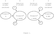
- Conductive polymers are chemically characterized by the so-called conjugation in which carbon double bonds periodically alternate with carbon single bonds along the polymer backbone (polypyrole, polyaniline, polyacetylene). Conductive polymers have a rather high electrical conductivity when doped with ions. Unlike in silicone, the dopants can be easily inserted and removed from the spaces they occupy between the polymer chains. In comparison with other semiconducting materials, the doping level can be very high: approximately one dopant counterion per four monomers. Construction of the actuators is possible due to the volume changes that take place in these materials during the changes in the doping level.
- the most studied conductive polymer actuators are based on a "conductive polymer film/no volume change film", where the conductive polymer is the only electromechanically active material.
- the conductive polymer film is connected as a working-electrode in an electromechanical cell; an additional counter-electrode and an electrolytic solution are necessary.
- the actuation mechanism of a conductive polymer actuator is based on an ionic exchange between the conductive polymer film and the electrolytic medium (either an electrolytic solution or a dry/wet polymer electrolyte). This is the most important factor that controls and limits the rather long response time of this kind of actuator.
- the low linear strain of the conductive polymer impedes the construction of the effective linear actuators working in the same way as natural muscles. This fact is an important limitation that has to be overcome looking for either new polymers or a new configuration where longitudinal changes should be amplified.
- Carbon nanotubes have exciting electrical and mechanical properties derived from their structure that consist of hollow cylinders of covalently bonded carbon. Double-layer charge injection seems to be the most promising actuation mechanism. This mechanism is quite distinct from that observed for conducting polymers. The ion flows, and consequently the electromechanical actuation behavior can be quite complex and is determined by the relative mobility of the polymer counter-ion and the ions in the electrolyte.
- the carbon nanotube acts as an electrochemical capacitor with the charge injected into the nanotube balanced by the electrical double-layer formed by movement of the electrolyte ions to the nanotube surface.
- the charge injection causes quantum chemically based dimensional changes in the carbon-carbon covalent bond length of the surface atoms close to the double layer. Short response times and high force density are expected from this mechanism based on the function of strong covalent bonds. However, the problem with a small low linear strain remains to be solved.
- Electrostatic repulsion between different tubes in the nanotube "forest” would cause repulsion between these tubes.
- An inter-tube electrostatic actuator mechanism may also be scientifically interesting.
- the stimulus-induced conformational change within the single molecule is the foundation of most biological molecular actuators.
- An example of the molecular actuator is the transport system powered by the motor protein kinesin.
- the random coil-to-helix transformation is among the most powerful conformational changes.
- the common principal disadvantage of biomolecular motors is their limited lifetime in vitro, and the narrow range of environmental conditions that they are able to tolerate.
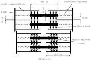
- Mammalian skeletal muscles are considered highly optimized systems evolved over more than 600 million years. They are made up of individual muscle fibers - single cells, which are up to several centimeters long, cylindrical with diameters about 10 ⁇ m, and surrounded by a cell membrane. The muscle cells are made up of parallel myofibrils. Myofibrils are built up from several micrometer axial long contractile units called sarcomeres, which contain three filament types: thin, thick and connecting ( Figure 2 ). Thick (myosin) and thin (actin) protein filaments inside the sarcomere are recognized to play a central role in contraction. The actin and myosin proteins have a contractile mechanism, which can be interpreted as both sliding and folding.
- the purpose of the present invention is to provide an electromechanical transducer capable of overcoming the drawbacks of the contemporary actuators.
- the surface of the particles, disks and filaments has the same electric charge, for instance, a negative one.
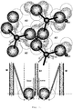
- the positions of the particles and filaments in the relaxation state are controlled by electrostatic repulsion forces in regular arrangement ( Figure 3 - Top).
- the filaments A1, A2, N, M, disks, and solid particles are placed in a liquid or gaseous medium.
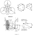
- the particles are arranged in a hexagonal lattice with the closest arrangement (hcp), according to Figures 5 and 6 .
- filaments A1 and A2 are surrounded by a layer of ions with an opposite charge to the charge on the surface of the whole part of the SNA.
- the layer of ions is advantageously made up of multivalent ions. For example, in the case of a negative charge on the filaments surface, an electrical field forces the ions to pass along filaments A1 and A2 from the disks. A high concentration of ions causes the collapse of the electrical double layer on the particles and filaments A1 and A2. The collapse subsequently causes local neutralization of their electrostatic repulsion.
- Constant influence of van der Waal's attractive forces in the area of filaments A1 and A2 causes mutual attraction of the particles and their contact with filaments A1 and A2.
- Contact of the particles with filaments A1 and A2 and the continuing attraction of the particles result in the tilt of the particles that drive filaments A1 and A2 toward the center, thereby shortening both the key elements of the SNA and the whole SNA.
- the SNA contracts by one single twitch, for instance 15 nm.
- the changes of the polarization of the disks force the ions to be cyclically transported to the particles and back to the disks.
- the main part of the energy supply is consumed by the ions return to the disks.
- the total contraction of the key element of the SNA is the product of the summation of the single twitches.
- the single twitches result from the alternating tillting of the particles and their return to the original positions.
- 100 twitches over 15 nm can induce a total contraction of a single element of up to 1.5 micrometers.
- the key elements of the actuator can be connected in series and/or parallel reaching the desired resulting movement and/or force.
- the total internal energy E 1 of the single particle in the three particle system is the sum of the mean kinetic energy of the thermal movement of the particle (3/2) kT and the potential energy of van der Waal's attractive bond in the direction of the bonds.
- k Boltzmann's constant 1.38E-23 (J/K)
- T the thermodynamic temperature (K).
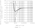
- Equation (3) substituting E1 for Equation (2), d for the smallest possible approach of the particles d 0 , and n for Equation (4), one obtains the dependence of the volume density energy ⁇ on the radius of the spherical particle R .
- Figure 4 demonstrates Equation (5).
- the course of the graph shows a distinct minimum.
- the minimum represents the lowest possible decrease of the volume density energy ⁇ at the radius of the particles R*.
- Equations (7) and (8) follow the basic rules for the construction of the single element of the SNA with the maximum transformed energy per volume unit and one single twitch;
- the surface of all components of the key element of the SNA is charged with the electrical charge of the same sign (for instance negative by specific absorption from the environment, by dissociation of the surface layers of particles, by electrical charges from outside the electrical circuit or by some other mechanism).
- the omnipresent same charge results in the omnipresent repulsion of all the components.
- the repulsion interaction between components results in the formation of a regular structure resembling the crystalline lattice.
- Distance d R determines the regular arrangement of the functional particles according to Figure 6 .
- the key element uses an array of triads to induce a powerful total force by multiplication of forces F A .
- SNA can provide engineering science with a simple analogy to the technical actuators of high performance; in comparison with the contemporary actuators in Table 1, the relevant sliding nanoactuators (SNA) have substantially smaller dimensions, larger deformation, shorter response time, higher wattage density, better positioning accuracy, and lower input voltage.
- Medicine and industry can primarily apply the sliding nanoactuator. Medicine can use such actuators for drug transportation, diagnostics, active biocompactible polymer implants instead of muscles with a driving voltage comparable to the action potentials, orthopedics, surgery and so on.
- the coming, electronics and micro (nano)-electro-mechanical-systems (MEMS, NEMS) will use the small size of the key element with short response time, low driving voltage, and large displacement with an exellent positioning accuracy. Large compound sytems with high performance can be built using the modular design from the nanometric size of the key elements.
- the SNA can be applied extensively for many control tasks in natural and artificial environments. Its microelectronic compatible input signals can be generated by the electronic control circuitry.
Landscapes
- Engineering & Computer Science (AREA)
- Chemical & Material Sciences (AREA)
- Combustion & Propulsion (AREA)
- Mechanical Engineering (AREA)
- General Engineering & Computer Science (AREA)
- Analytical Chemistry (AREA)
- Computer Hardware Design (AREA)
- Microelectronics & Electronic Packaging (AREA)
- Micromachines (AREA)
- Prostheses (AREA)
- Inert Electrodes (AREA)
Claims (2)
- Elektromechanischer wandler, hier wie sliding nanoactuator SNA gennant, enthaltend die grundlegende Elemente, aus denen jede besteht aus• bestimmte Menge von elektrisch halbleitende Fasern (A1), die mit dem ersten elektrisch halbleitend Disk verbunden sind;• bestimmte Menge von zweiten elektrisch halbleitend Fasern (A2), die mit dem zweiten elektrisch halbleitend Disk verbunden sind;• wo die ersten halbleitenden Fasern (A1) auf den zweiten halbleitenden Disk und die zweiten halbleitenden Fasern (A2) auf den ersten halbleitenden Disk gerichtet sind, wobei die beide halbleitende Diske die entgegensetzte Ende von SNA definieren;• wo gibt es die symmetrische Distribution von mindestens drei Partikeln die rund der ersten und zweiten halbleitenden Fasern (A1 und A2) sind, sind diese Partikeln auf den dritten Fasern verankert (N), die dritten Fasern in einem Bündel verbünded sind und eine stärkere Faser zusammen bilden (M), die zwischen den ersten und zweiten halbleitenden Faser (A1 und A2) eingelagert ist;• wo die Oberfläche von den Partikeln, Disken und Fasern die selbe elektrische Ladung haben, die mit dem Einfluss von abstossend elektrostatich Kräfte die Stellung von den Partikeln und Fasern in einem entspannend Stand richtet;• wo im Kontraktion Stand die ersten und zweiten halbleitenden Fasern (A1 und A2) mit der Ionschicht umgegeben sind, diese Ionschicht hat eine entgegensetzte Ladung als die Ladung auf der ganzen Oberfläche des SNA, was ruft eine lokale Neutralization der elektrostatischen Abstossung hervor;• wo der ständig Einfluss von den van der Waals anziennd Kräfte im Bereich von den ersten und zweiten halbleitenden Fasern (A1 und A2) ruft die gegenseitige Anziehung von den Partikeln und ihren Kontakt mit den schon erwähnten ersten und zweiten Fasern (A1 und A2) heraus, die fortgesetzte Anziehung von den Partikeln führt zu ihre Neigung und die Schubbewegung von den schon erwähnten ersten und zweiten Fasern (A1 und A2) zu der Mitte von SNA, wodurch führt der erste und zweite halbleitende Disk zu der gegenseitige Annäherung und Kontraktion von dem ganzen SNA;• wo die Partikeln mit Hilfe von eine Gleichung optimal Messungen haben R* = 27kTd0/H, wo Sphären mit der Radius R* vorstellen die Grösse von die Partikeln, k die Boltzmann Konstante, T die thermodynamisch Temperature, d0 mindest möglich Näherung von Particles, H Hammaker Konstante von Material von Particles haben zur Erreichung des maximal Rückgangs von der inneren Energie,• wo die wiederholten kleinen Verschiebungen zwischen die Fasern (A1 und A2) sich kumulieren und relativ gross Verschiebungen verursachen.
- Elektromechaniser wandler SNA nach dem Anspruch 1, wo seine grosse gesamte Kontraktion bildet sich von Summation der Kontraktionen der schon erwähnten grundlegenden Elemente in einer Serienanordnung heraus und die gesamte Kraft des elektromechaniser wandler bildet sich von die Summation der Kräfte der grundlegenden Elemente in einer parallelanordnung heraus.
Applications Claiming Priority (2)
| Application Number | Priority Date | Filing Date | Title |
|---|---|---|---|
| CZ2005-828A CZ307391B6 (cs) | 2005-12-30 | 2005-12-30 | Elektromechanický měnič |
| PCT/CZ2006/000094 WO2007076732A2 (en) | 2005-12-30 | 2006-12-21 | Electromechanical transducer |
Publications (2)
| Publication Number | Publication Date |
|---|---|
| EP2002535A2 EP2002535A2 (de) | 2008-12-17 |
| EP2002535B1 true EP2002535B1 (de) | 2019-05-15 |
Family
ID=38227710
Family Applications (1)
| Application Number | Title | Priority Date | Filing Date |
|---|---|---|---|
| EP06828476.9A Not-in-force EP2002535B1 (de) | 2005-12-30 | 2006-12-21 | Elektromechanischer wandler |
Country Status (6)
| Country | Link |
|---|---|
| US (1) | US7994685B2 (de) |
| EP (1) | EP2002535B1 (de) |
| JP (1) | JP5380076B2 (de) |
| CZ (1) | CZ307391B6 (de) |
| EA (1) | EA013443B1 (de) |
| WO (1) | WO2007076732A2 (de) |
Families Citing this family (3)
| Publication number | Priority date | Publication date | Assignee | Title |
|---|---|---|---|---|
| KR101903632B1 (ko) | 2017-03-29 | 2018-10-04 | 한국과학기술연구원 | 인공 근절 구조체 |
| CN109356963B (zh) * | 2017-11-07 | 2020-04-07 | 北京航空航天大学 | 一种电磁铁与sma板耦合的可变主动调节多胞元阻尼器 |
| CN114501964B (zh) * | 2022-04-02 | 2022-08-30 | 浙大城市学院 | 一种基于压电激振的动态壁面换热装置 |
Family Cites Families (9)
| Publication number | Priority date | Publication date | Assignee | Title |
|---|---|---|---|---|
| IT1235887B (it) * | 1989-06-14 | 1992-11-23 | Consiglio Nazionale Ricerche | Materiale composito contrattile e dispositivi elettromeccanochimici che lo utilizzano, in particolare muscoli artificiali e dispositivi sensori |
| JP3515134B2 (ja) * | 1992-03-04 | 2004-04-05 | 正喜 江刺 | 静電マイクロアクチュエーター |
| DE60040226D1 (de) * | 1999-08-03 | 2008-10-23 | Us Gov Health & Human Serv | Molekularer motor |
| JP2001189051A (ja) * | 1999-12-28 | 2001-07-10 | Pioneer Electronic Corp | コード判定装置及び方法、記録媒体判別装置及び方法並びに情報記録装置及び方法 |
| JP2002330598A (ja) * | 2001-05-02 | 2002-11-15 | National Institute Of Advanced Industrial & Technology | 積層型高分子アクチュエータ |
| AU2003284274A1 (en) * | 2002-10-18 | 2004-05-04 | Florida State University | Biomolecular-based actuator |
| JP4250536B2 (ja) * | 2004-01-16 | 2009-04-08 | パナソニック株式会社 | 導電性高分子アクチュエータ |
| JP2005230957A (ja) * | 2004-02-18 | 2005-09-02 | Institute Of Physical & Chemical Research | 直動人工筋アクチュエータ |
| WO2009084323A1 (ja) * | 2007-12-27 | 2009-07-09 | Murata Manufacturing Co., Ltd. | アクチュエータ |
-
2005
- 2005-12-30 CZ CZ2005-828A patent/CZ307391B6/cs not_active IP Right Cessation
-
2006
- 2006-12-21 EA EA200801609A patent/EA013443B1/ru not_active IP Right Cessation
- 2006-12-21 US US12/087,261 patent/US7994685B2/en not_active Expired - Fee Related
- 2006-12-21 EP EP06828476.9A patent/EP2002535B1/de not_active Not-in-force
- 2006-12-21 WO PCT/CZ2006/000094 patent/WO2007076732A2/en not_active Ceased
- 2006-12-21 JP JP2008547844A patent/JP5380076B2/ja not_active Expired - Fee Related
Non-Patent Citations (1)
| Title |
|---|
| None * |
Also Published As
| Publication number | Publication date |
|---|---|
| CZ2005828A3 (cs) | 2007-07-11 |
| EP2002535A2 (de) | 2008-12-17 |
| WO2007076732A3 (en) | 2007-09-20 |
| JP5380076B2 (ja) | 2014-01-08 |
| EA200801609A1 (ru) | 2009-02-27 |
| US7994685B2 (en) | 2011-08-09 |
| JP2009522115A (ja) | 2009-06-11 |
| US20090179520A1 (en) | 2009-07-16 |
| WO2007076732A2 (en) | 2007-07-12 |
| EA013443B1 (ru) | 2010-04-30 |
| CZ307391B6 (cs) | 2018-07-25 |
Similar Documents
| Publication | Publication Date | Title |
|---|---|---|
| Mirvakili et al. | Artificial muscles: mechanisms, applications, and challenges | |
| Shahinpoor | Artificial muscles: applications of advanced polymeric nanocomposites | |
| Carpi et al. | Electroactive polymer actuators as artificial muscles: are they ready for bioinspired applications? | |
| Bar-Cohen et al. | Electroactive polymer actuators and sensors | |
| Brochu et al. | Dielectric elastomers for actuators and artificial muscles | |
| Mirfakhrai et al. | Polymer artificial muscles | |
| Martins et al. | Polymer-based actuators: back to the future | |
| Shankar et al. | Dielectric elastomers as next-generation polymeric actuators | |
| Bar-Cohen | Electroactive polymers as artificial muscles-reality and challenges | |
| Hines et al. | Soft actuators for small‐scale robotics | |
| CN1910810B (zh) | 促动器及促动器用平板状电极支撑体的制造方法 | |
| Bar-Cohen | Electroactive polymer actuators as artificial muscles | |
| Wax et al. | Electroactive polymer actuators and devices | |
| Shahinpoor et al. | Ionic polymer-metal composites (IPMCs) as biomimetic sensors, actuators and artificial muscles-a review | |
| Wu et al. | Extraordinary electromechanical actuation of Ti2C MXene | |
| Samatham et al. | Active polymers: an overview | |
| Akle | Characterization and modeling of the ionomer-conductor interface in ionic polymer transducers | |
| JP2005051949A (ja) | アクチュエータ及びそれを用いた関節駆動機構 | |
| Fu et al. | Recent progress of morphable 3D mesostructures in advanced materials | |
| US7994685B2 (en) | Electromechanical transducer—artificial muscle | |
| Shabani et al. | Nanomaterials in Actuators—A Review | |
| Madden et al. | Dielectric elastomers as high-performance electroactive polymers | |
| Shahinpoor | Artificial muscles | |
| Citérin et al. | Electro-active polymer actuators for tactile displays | |
| Carpi et al. | Electroactive polymer artificial muscles: an overview |
Legal Events
| Date | Code | Title | Description |
|---|---|---|---|
| PUAI | Public reference made under article 153(3) epc to a published international application that has entered the european phase |
Free format text: ORIGINAL CODE: 0009012 |
|
| 17P | Request for examination filed |
Effective date: 20080723 |
|
| AK | Designated contracting states |
Kind code of ref document: A2 Designated state(s): AT BE BG CH CY CZ DE DK EE ES FI FR GB GR HU IE IS IT LI LT LU LV MC NL PL PT RO SE SI SK TR |
|
| 17Q | First examination report despatched |
Effective date: 20090202 |
|
| DAX | Request for extension of the european patent (deleted) | ||
| STAA | Information on the status of an ep patent application or granted ep patent |
Free format text: STATUS: EXAMINATION IS IN PROGRESS |
|
| RIC1 | Information provided on ipc code assigned before grant |
Ipc: F03G 7/06 20060101ALI20181107BHEP Ipc: H02N 11/00 20060101AFI20181107BHEP Ipc: B81B 3/00 20060101ALI20181107BHEP Ipc: F03G 7/00 20060101ALI20181107BHEP Ipc: B82B 1/00 20060101ALI20181107BHEP |
|
| GRAP | Despatch of communication of intention to grant a patent |
Free format text: ORIGINAL CODE: EPIDOSNIGR1 |
|
| STAA | Information on the status of an ep patent application or granted ep patent |
Free format text: STATUS: GRANT OF PATENT IS INTENDED |
|
| INTG | Intention to grant announced |
Effective date: 20190108 |
|
| GRAJ | Information related to disapproval of communication of intention to grant by the applicant or resumption of examination proceedings by the epo deleted |
Free format text: ORIGINAL CODE: EPIDOSDIGR1 |
|
| STAA | Information on the status of an ep patent application or granted ep patent |
Free format text: STATUS: EXAMINATION IS IN PROGRESS |
|
| GRAP | Despatch of communication of intention to grant a patent |
Free format text: ORIGINAL CODE: EPIDOSNIGR1 |
|
| STAA | Information on the status of an ep patent application or granted ep patent |
Free format text: STATUS: GRANT OF PATENT IS INTENDED |
|
| INTC | Intention to grant announced (deleted) | ||
| GRAS | Grant fee paid |
Free format text: ORIGINAL CODE: EPIDOSNIGR3 |
|
| GRAA | (expected) grant |
Free format text: ORIGINAL CODE: 0009210 |
|
| STAA | Information on the status of an ep patent application or granted ep patent |
Free format text: STATUS: THE PATENT HAS BEEN GRANTED |
|
| INTG | Intention to grant announced |
Effective date: 20190318 |
|
| AK | Designated contracting states |
Kind code of ref document: B1 Designated state(s): AT BE BG CH CY CZ DE DK EE ES FI FR GB GR HU IE IS IT LI LT LU LV MC NL PL PT RO SE SI SK TR |
|
| REG | Reference to a national code |
Ref country code: CH Ref legal event code: EP Ref country code: GB Ref legal event code: FG4D |
|
| REG | Reference to a national code |
Ref country code: DE Ref legal event code: R096 Ref document number: 602006057992 Country of ref document: DE |
|
| REG | Reference to a national code |
Ref country code: IE Ref legal event code: FG4D |
|
| REG | Reference to a national code |
Ref country code: NL Ref legal event code: MP Effective date: 20190515 |
|
| REG | Reference to a national code |
Ref country code: LT Ref legal event code: MG4D |
|
| PG25 | Lapsed in a contracting state [announced via postgrant information from national office to epo] |
Ref country code: FI Free format text: LAPSE BECAUSE OF FAILURE TO SUBMIT A TRANSLATION OF THE DESCRIPTION OR TO PAY THE FEE WITHIN THE PRESCRIBED TIME-LIMIT Effective date: 20190515 Ref country code: SE Free format text: LAPSE BECAUSE OF FAILURE TO SUBMIT A TRANSLATION OF THE DESCRIPTION OR TO PAY THE FEE WITHIN THE PRESCRIBED TIME-LIMIT Effective date: 20190515 Ref country code: LT Free format text: LAPSE BECAUSE OF FAILURE TO SUBMIT A TRANSLATION OF THE DESCRIPTION OR TO PAY THE FEE WITHIN THE PRESCRIBED TIME-LIMIT Effective date: 20190515 Ref country code: ES Free format text: LAPSE BECAUSE OF FAILURE TO SUBMIT A TRANSLATION OF THE DESCRIPTION OR TO PAY THE FEE WITHIN THE PRESCRIBED TIME-LIMIT Effective date: 20190515 Ref country code: NL Free format text: LAPSE BECAUSE OF FAILURE TO SUBMIT A TRANSLATION OF THE DESCRIPTION OR TO PAY THE FEE WITHIN THE PRESCRIBED TIME-LIMIT Effective date: 20190515 Ref country code: PT Free format text: LAPSE BECAUSE OF FAILURE TO SUBMIT A TRANSLATION OF THE DESCRIPTION OR TO PAY THE FEE WITHIN THE PRESCRIBED TIME-LIMIT Effective date: 20190915 |
|
| PG25 | Lapsed in a contracting state [announced via postgrant information from national office to epo] |
Ref country code: GR Free format text: LAPSE BECAUSE OF FAILURE TO SUBMIT A TRANSLATION OF THE DESCRIPTION OR TO PAY THE FEE WITHIN THE PRESCRIBED TIME-LIMIT Effective date: 20190816 Ref country code: LV Free format text: LAPSE BECAUSE OF FAILURE TO SUBMIT A TRANSLATION OF THE DESCRIPTION OR TO PAY THE FEE WITHIN THE PRESCRIBED TIME-LIMIT Effective date: 20190515 Ref country code: BG Free format text: LAPSE BECAUSE OF FAILURE TO SUBMIT A TRANSLATION OF THE DESCRIPTION OR TO PAY THE FEE WITHIN THE PRESCRIBED TIME-LIMIT Effective date: 20190815 |
|
| REG | Reference to a national code |
Ref country code: AT Ref legal event code: MK05 Ref document number: 1134606 Country of ref document: AT Kind code of ref document: T Effective date: 20190515 |
|
| PG25 | Lapsed in a contracting state [announced via postgrant information from national office to epo] |
Ref country code: CZ Free format text: LAPSE BECAUSE OF FAILURE TO SUBMIT A TRANSLATION OF THE DESCRIPTION OR TO PAY THE FEE WITHIN THE PRESCRIBED TIME-LIMIT Effective date: 20190515 Ref country code: RO Free format text: LAPSE BECAUSE OF FAILURE TO SUBMIT A TRANSLATION OF THE DESCRIPTION OR TO PAY THE FEE WITHIN THE PRESCRIBED TIME-LIMIT Effective date: 20190515 Ref country code: AT Free format text: LAPSE BECAUSE OF FAILURE TO SUBMIT A TRANSLATION OF THE DESCRIPTION OR TO PAY THE FEE WITHIN THE PRESCRIBED TIME-LIMIT Effective date: 20190515 Ref country code: DK Free format text: LAPSE BECAUSE OF FAILURE TO SUBMIT A TRANSLATION OF THE DESCRIPTION OR TO PAY THE FEE WITHIN THE PRESCRIBED TIME-LIMIT Effective date: 20190515 Ref country code: EE Free format text: LAPSE BECAUSE OF FAILURE TO SUBMIT A TRANSLATION OF THE DESCRIPTION OR TO PAY THE FEE WITHIN THE PRESCRIBED TIME-LIMIT Effective date: 20190515 Ref country code: SK Free format text: LAPSE BECAUSE OF FAILURE TO SUBMIT A TRANSLATION OF THE DESCRIPTION OR TO PAY THE FEE WITHIN THE PRESCRIBED TIME-LIMIT Effective date: 20190515 |
|
| PGFP | Annual fee paid to national office [announced via postgrant information from national office to epo] |
Ref country code: DE Payment date: 20190912 Year of fee payment: 14 |
|
| REG | Reference to a national code |
Ref country code: DE Ref legal event code: R097 Ref document number: 602006057992 Country of ref document: DE |
|
| PG25 | Lapsed in a contracting state [announced via postgrant information from national office to epo] |
Ref country code: IT Free format text: LAPSE BECAUSE OF FAILURE TO SUBMIT A TRANSLATION OF THE DESCRIPTION OR TO PAY THE FEE WITHIN THE PRESCRIBED TIME-LIMIT Effective date: 20190515 |
|
| PLBE | No opposition filed within time limit |
Free format text: ORIGINAL CODE: 0009261 |
|
| STAA | Information on the status of an ep patent application or granted ep patent |
Free format text: STATUS: NO OPPOSITION FILED WITHIN TIME LIMIT |
|
| PG25 | Lapsed in a contracting state [announced via postgrant information from national office to epo] |
Ref country code: TR Free format text: LAPSE BECAUSE OF FAILURE TO SUBMIT A TRANSLATION OF THE DESCRIPTION OR TO PAY THE FEE WITHIN THE PRESCRIBED TIME-LIMIT Effective date: 20190515 |
|
| 26N | No opposition filed |
Effective date: 20200218 |
|
| PG25 | Lapsed in a contracting state [announced via postgrant information from national office to epo] |
Ref country code: PL Free format text: LAPSE BECAUSE OF FAILURE TO SUBMIT A TRANSLATION OF THE DESCRIPTION OR TO PAY THE FEE WITHIN THE PRESCRIBED TIME-LIMIT Effective date: 20190515 |
|
| PG25 | Lapsed in a contracting state [announced via postgrant information from national office to epo] |
Ref country code: SI Free format text: LAPSE BECAUSE OF FAILURE TO SUBMIT A TRANSLATION OF THE DESCRIPTION OR TO PAY THE FEE WITHIN THE PRESCRIBED TIME-LIMIT Effective date: 20190515 |
|
| REG | Reference to a national code |
Ref country code: CH Ref legal event code: PL |
|
| REG | Reference to a national code |
Ref country code: BE Ref legal event code: MM Effective date: 20191231 |
|
| PG25 | Lapsed in a contracting state [announced via postgrant information from national office to epo] |
Ref country code: MC Free format text: LAPSE BECAUSE OF FAILURE TO SUBMIT A TRANSLATION OF THE DESCRIPTION OR TO PAY THE FEE WITHIN THE PRESCRIBED TIME-LIMIT Effective date: 20190515 |
|
| GBPC | Gb: european patent ceased through non-payment of renewal fee |
Effective date: 20191221 |
|
| PG25 | Lapsed in a contracting state [announced via postgrant information from national office to epo] |
Ref country code: FR Free format text: LAPSE BECAUSE OF NON-PAYMENT OF DUE FEES Effective date: 20191231 Ref country code: IE Free format text: LAPSE BECAUSE OF NON-PAYMENT OF DUE FEES Effective date: 20191221 Ref country code: LU Free format text: LAPSE BECAUSE OF NON-PAYMENT OF DUE FEES Effective date: 20191221 Ref country code: GB Free format text: LAPSE BECAUSE OF NON-PAYMENT OF DUE FEES Effective date: 20191221 |
|
| PG25 | Lapsed in a contracting state [announced via postgrant information from national office to epo] |
Ref country code: LI Free format text: LAPSE BECAUSE OF NON-PAYMENT OF DUE FEES Effective date: 20191231 Ref country code: BE Free format text: LAPSE BECAUSE OF NON-PAYMENT OF DUE FEES Effective date: 20191231 Ref country code: CH Free format text: LAPSE BECAUSE OF NON-PAYMENT OF DUE FEES Effective date: 20191231 |
|
| PG25 | Lapsed in a contracting state [announced via postgrant information from national office to epo] |
Ref country code: CY Free format text: LAPSE BECAUSE OF FAILURE TO SUBMIT A TRANSLATION OF THE DESCRIPTION OR TO PAY THE FEE WITHIN THE PRESCRIBED TIME-LIMIT Effective date: 20190515 |
|
| PG25 | Lapsed in a contracting state [announced via postgrant information from national office to epo] |
Ref country code: IS Free format text: LAPSE BECAUSE OF FAILURE TO SUBMIT A TRANSLATION OF THE DESCRIPTION OR TO PAY THE FEE WITHIN THE PRESCRIBED TIME-LIMIT Effective date: 20190915 |
|
| REG | Reference to a national code |
Ref country code: DE Ref legal event code: R119 Ref document number: 602006057992 Country of ref document: DE |
|
| PG25 | Lapsed in a contracting state [announced via postgrant information from national office to epo] |
Ref country code: HU Free format text: LAPSE BECAUSE OF FAILURE TO SUBMIT A TRANSLATION OF THE DESCRIPTION OR TO PAY THE FEE WITHIN THE PRESCRIBED TIME-LIMIT; INVALID AB INITIO Effective date: 20061221 |
|
| PG25 | Lapsed in a contracting state [announced via postgrant information from national office to epo] |
Ref country code: DE Free format text: LAPSE BECAUSE OF NON-PAYMENT OF DUE FEES Effective date: 20210701 |