EP2002665B1 - Dispositif répartiteur d'une installation de télécommunication, pourvu d'un dispositif de compensation - Google Patents
Dispositif répartiteur d'une installation de télécommunication, pourvu d'un dispositif de compensation Download PDFInfo
- Publication number
- EP2002665B1 EP2002665B1 EP07722897A EP07722897A EP2002665B1 EP 2002665 B1 EP2002665 B1 EP 2002665B1 EP 07722897 A EP07722897 A EP 07722897A EP 07722897 A EP07722897 A EP 07722897A EP 2002665 B1 EP2002665 B1 EP 2002665B1
- Authority
- EP
- European Patent Office
- Prior art keywords
- contact
- connection
- compensation
- cable cores
- functional element
- Prior art date
- Legal status (The legal status is an assumption and is not a legal conclusion. Google has not performed a legal analysis and makes no representation as to the accuracy of the status listed.)
- Not-in-force
Links
- 210000002105 tongue Anatomy 0.000 claims description 7
- 230000000694 effects Effects 0.000 claims description 2
- 230000010363 phase shift Effects 0.000 claims description 2
- 230000002708 enhancing effect Effects 0.000 claims 1
- 230000002123 temporal effect Effects 0.000 claims 1
- 230000005540 biological transmission Effects 0.000 description 8
- 238000012856 packing Methods 0.000 description 2
- 230000015572 biosynthetic process Effects 0.000 description 1
- 230000034303 cell budding Effects 0.000 description 1
- 230000001419 dependent effect Effects 0.000 description 1
- 230000001771 impaired effect Effects 0.000 description 1
- 238000003780 insertion Methods 0.000 description 1
- 230000037431 insertion Effects 0.000 description 1
Images

Classifications
-
- H—ELECTRICITY
- H04—ELECTRIC COMMUNICATION TECHNIQUE
- H04Q—SELECTING
- H04Q1/00—Details of selecting apparatus or arrangements
- H04Q1/02—Constructional details
- H04Q1/14—Distribution frames
- H04Q1/142—Terminal blocks for distribution frames
-
- H—ELECTRICITY
- H04—ELECTRIC COMMUNICATION TECHNIQUE
- H04M—TELEPHONIC COMMUNICATION
- H04M3/00—Automatic or semi-automatic exchanges
- H04M3/18—Automatic or semi-automatic exchanges with means for reducing interference or noise; with means for reducing effects due to line faults with means for protecting lines
-
- H—ELECTRICITY
- H04—ELECTRIC COMMUNICATION TECHNIQUE
- H04Q—SELECTING
- H04Q2201/00—Constructional details of selecting arrangements
- H04Q2201/02—Details of frames
-
- H—ELECTRICITY
- H04—ELECTRIC COMMUNICATION TECHNIQUE
- H04Q—SELECTING
- H04Q2201/00—Constructional details of selecting arrangements
- H04Q2201/80—Constructional details of selecting arrangements in specific systems
- H04Q2201/802—Constructional details of selecting arrangements in specific systems in data transmission systems
Definitions
- the DE 100 29 870 A1 discloses a distribution block designed as a distribution device of a telecommunications system with a receptacle in which a plurality of distribution strips and wire guide elements are positioned in a sandwich over each other.
- Each distributor strip has a functional element which preferably has contact elements designed as IDC contacts on one front side for connecting incoming and outgoing cable cores.
- the wire guide elements have wire guide levels forming wire guide channels for guiding the cable core.
- the distribution strips and the wire guide elements are sandwiched over one another such that at least one wire guide plane with wire guide channels is positioned between two adjacent distribution strips.
- the high-frequency data signal from the cable core on which the combined voice-data signal is transmitted, bypassing an xDSL splitter device, can jump over to the cable core on which only the low-frequency voice signal is to be transmitted.
- the present invention is based on the problem to provide a novel distribution device of a telecommunications system.
- the compensation devices are integrated in the electrical signal path between contact elements for the connection of incoming cable cores and contact elements for the connection of outgoing cable cores, namely either solvable or insoluble.
- transmission disturbances caused by crosstalk or crosstalk in the distributor strip or in the distributor block can be removed from the signals to be transmitted. This is a clear difference from the prior art, in which it is attempted only by shielding devices to prevent crosstalk caused by crosstalk or transmission interference.
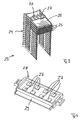
- Fig. 1 shows a first embodiment of an inventive, designed as a distributor strip, distribution device of a telecommunications system.
- distributor strip 10 has a functional element, wherein the functional element has on a front side of the distribution strip 10 a plurality of contact elements designed as IDC contacts.
- the compensation devices have active and / or passive components to compensate for crosstalk caused by crosstalk or crosstalk transmission.
- the compensation devices 14 are integrated into the functional element of the distributor strip 10 such that each compensation device 14 is permanently connected in the corresponding electrical connection path between the contact elements 11 and 12.
- the contact elements 16 for the connection of incoming cable cores and the contact elements 17 for the connection of outgoing cable cores are in turn arranged in a row next to each other, wherein the series with the contact elements 16 for the connection of incoming cable cores in Fig. 2 is arranged above the row with the contact elements 17 for the connection of outgoing cable cores.
- contact springs are electrically connected to the contact elements 16 and 17, the contact springs serving to establish connections between incoming cable cores and outgoing cable cores.
- Fig. 2 In turn, only thosemaschinefedem 18 are visible, which are electrically connected to the contact elements 16.
- the distribution strip 15 of the embodiment of the Fig. 2 includes compensation means 19 which serve to compensate for crosstalk caused by crosstalk.
- Fig. 2 can be removed, 17 openings 22 are formed between the extending at the front rows of first contact elements 16 and second contact elements, in which the contact tongues 21 are inserted to electrically conductive contact with the contact springs and so the compensation means 19 releasably in the electrical To integrate connection paths between the contact elements 16 and 17.
- compensation means 27 are integrated, wherein the compensation means 27 are connected in the electrical connection path between the contact elements for the connection of incoming cable cores and the contact elements for the connection of outgoing cable cores.
- the compensation devices 27 assigned to a distributor strip 25 are again combined to form a cassette element 28, wherein the cassette element 28 can be inserted via a contact strip 29 on a rear side of a functional element and thus on a rear side of a distributor strip 25 between the contact springs of the functional element.
- Fig. 2 illustrated variant in which the cassette element is introduced at the front in a distribution strip, has the insertion of the cassette element at a rear side of the distribution strip according to 3 and 4 on the advantage that the positioned on the front sides of the distribution strip, designed as IDC contacts contact elements for connecting budding cable cores and outgoing cable cores are freely accessible.
- Fig. 2 such as Fig. 3 to 4 have over the embodiment of the Fig. 1 on the advantage that already installed in the field distribution devices can be easily retrofitted by the cassette elements.
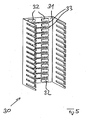
- Fig. 5 shows a receptacle 30 of a distributor block according to the invention according to a further embodiment of the present invention, wherein in the embodiment of the Fig. 5 Compensation devices 32 are arranged on a rear side 31 of receptacle 30 and are integrated into receptacle 30.
- distribution strips can be electrically connected with their Girdles via interfaces 33 which are also formed on the rear wall 31 of the receptacle 30 with the compensation means 32, to ultimately in the communication path between contact elements for the connection incoming cable cores and contact elements for connecting outgoing cable cores to integrate.
- the stages of a multi-stage compensator are offset and integrated in series into an electrical connection path between an incoming cable core contact element and an outgoing cable wire contact element to utilize time shifts and / or stage phase shifts to enhance the compensation effect.
- the compensation devices are preferably designed such that they serve to compensate crosstalk or crosstalk between cable cores of different subscribers.
- the compensation means are preferably designed such that they serve to compensate for crosstalk or cross-talk between cable wires of the same subscriber.
- the compensation devices are integrated either detachably or non-detachably into the respective electrical connection paths between contact elements for the connection of incoming cable cores and contact elements for the connection of outgoing cable cores.
Landscapes
- Engineering & Computer Science (AREA)
- Computer Networks & Wireless Communication (AREA)
- Details Of Connecting Devices For Male And Female Coupling (AREA)
- Coupling Device And Connection With Printed Circuit (AREA)
Claims (8)
- Barrette de distribution d'un équipement de télécommunication comprenant un élément fonctionnel, l'élément fonctionnel présentant des éléments de contact pour le raccordement de conducteurs de câble arrivants et des éléments de contact pour le raccordement de conducteurs de câble partants, et l'élément fonctionnel présentant en outre des ressorts de contact reliés de manière électriquement conductrice avec les éléments de contact pour établir des liaisons entre les conducteurs de câble arrivants et les conducteurs de câble partants, caractérisée par au moins un dispositif de compensation (14 ; 19 ; 27) à plusieurs étages qui est intégré dans un trajet de liaison électrique entre un élément de contact pour le raccordement d'un conducteur de câble arrivant et un élément de contact pour le raccordement d'un conducteur de câble partant, le ou chaque dispositif de compensation (14 ; 19 ; 27) servant à la compensation de la diaphonie ou de la transmodulation entre les conducteurs de câble de différents abonnés par le biais d'une compensation brute et d'une compensation fine, les étages d'un dispositif de compensation à plusieurs étages étant décalés et intégrés en série dans un trajet de liaison électrique entre un élément de contact pour le raccordement d'un conducteur de câble arrivant et un élément de contact pour le raccordement d'un conducteur de câble partant, de telle sorte que les décalages dans le temps et/ou les déphasages des étages peuvent être utilisés pour amplifier l'effet de compensation.
- Barrette de distribution selon la revendication 1, caractérisée en ce que le ou chaque dispositif de compensation (14) est intégré dans l'élément fonctionnel de telle sorte que le ou chaque dispositif de compensation (14) est connecté de manière inamovible dans le trajet de liaison électrique correspondant entre un élément de contact pour le raccordement d'un conducteur de câble arrivant et un élément de contact pour le raccordement d'un conducteur de câble partant.
- Barrette de distribution selon la revendication 1, caractérisée en ce que le ou chaque dispositif de compensation (19 ; 27) est intégré dans l'élément fonctionnel de telle sorte que le ou chaque dispositif de compensation (19 ; 27) est connecté de manière amovible dans le trajet de liaison électrique correspondant entre un élément de contact pour le raccordement d'un conducteur de câble arrivant et un élément de contact pour le raccordement d'un conducteur de câble partant.
- Barrette de distribution selon la revendication 3, caractérisée en ce que les dispositifs de compensation (27) pour différents abonnés sont regroupés en un élément en cassette (28) qui présente une barrette de contact (29) par le biais de laquelle celui-ci peut être introduit au niveau d'un côté arrière de l'élément fonctionnel entre les ressorts de contact de l'élément fonctionnel.
- Barrette de distribution selon la revendication 3, caractérisée en ce que les dispositifs de compensation (19) pour différents abonnés sont regroupés en une platine (20) qui présente des languettes de contact (21) par le biais desquelles celle-ci peut être introduite au niveau d'un côté avant de l'élément fonctionnel entre les ressorts de contact de l'élément fonctionnel.
- Barrette de distribution selon la revendication 3, caractérisée en ce que chaque dispositif de compensation pour un abonné est réalisé sous la forme d'une fiche individuelle et peut être introduit par le biais de languettes de contact individuelles au niveau d'un côté avant de l'élément fonctionnel entre les ressorts de contact de l'élément fonctionnel.
- Barrette de distribution selon une ou plusieurs des revendications 1 à 6, caractérisée en ce que des dispositifs séparateurs xDSL supplémentaires sont intégrés en plus des dispositifs de compensation dans le trajet de liaison électrique entre les éléments de contact pour le raccordement d'un conducteur de câble arrivant et les éléments de contact pour le raccordement d'un conducteur de câble partant.
- Barrette de distribution selon la revendication 7, caractérisée en ce que le ou chaque dispositif de compensation est configuré de telle sorte que celui-ci sert à la compensation de la diaphonie ou de la transmodulation entre les conducteurs de câble.
Applications Claiming Priority (2)
| Application Number | Priority Date | Filing Date | Title |
|---|---|---|---|
| DE200620005683 DE202006005683U1 (de) | 2006-04-05 | 2006-04-05 | Verteilereinrichtung einer Telekommunikatiosanlage |
| PCT/EP2007/001521 WO2007115604A1 (fr) | 2006-04-05 | 2007-02-22 | Dispositif répartiteur d'une installation de télécommunication, pourvu d'un dispositif de compensation |
Publications (2)
| Publication Number | Publication Date |
|---|---|
| EP2002665A1 EP2002665A1 (fr) | 2008-12-17 |
| EP2002665B1 true EP2002665B1 (fr) | 2012-10-24 |
Family
ID=36776687
Family Applications (1)
| Application Number | Title | Priority Date | Filing Date |
|---|---|---|---|
| EP07722897A Not-in-force EP2002665B1 (fr) | 2006-04-05 | 2007-02-22 | Dispositif répartiteur d'une installation de télécommunication, pourvu d'un dispositif de compensation |
Country Status (3)
| Country | Link |
|---|---|
| EP (1) | EP2002665B1 (fr) |
| DE (1) | DE202006005683U1 (fr) |
| WO (1) | WO2007115604A1 (fr) |
Family Cites Families (4)
| Publication number | Priority date | Publication date | Assignee | Title |
|---|---|---|---|---|
| DE10029870A1 (de) * | 2000-06-16 | 2002-01-03 | Rxs Kabelgarnituren Gmbh & Co | Verteilereinrichtung einer Datensignal-Verarbeitungsanlage und Datensignal-Verarbeitungsanlage |
| EP1455418A1 (fr) * | 2003-03-03 | 2004-09-08 | 3M Innovative Properties Company | Module de télécommunication |
| CN1902785A (zh) * | 2003-11-21 | 2007-01-24 | 莱维顿制造有限公司 | 串扰减少的插线面板系统和方法 |
| US7187766B2 (en) * | 2004-02-20 | 2007-03-06 | Adc Incorporated | Methods and systems for compensating for alien crosstalk between connectors |
-
2006
- 2006-04-05 DE DE200620005683 patent/DE202006005683U1/de not_active Expired - Lifetime
-
2007
- 2007-02-22 WO PCT/EP2007/001521 patent/WO2007115604A1/fr not_active Ceased
- 2007-02-22 EP EP07722897A patent/EP2002665B1/fr not_active Not-in-force
Also Published As
| Publication number | Publication date |
|---|---|
| WO2007115604A1 (fr) | 2007-10-18 |
| EP2002665A1 (fr) | 2008-12-17 |
| DE202006005683U1 (de) | 2006-07-20 |
Similar Documents
| Publication | Publication Date | Title |
|---|---|---|
| EP1290762B1 (fr) | Module distributeur a connexions utilise en telecommunications et dans des systemes de donnees | |
| EP1527503B1 (fr) | Module de connexion de dispositif de distribution utilise en technique de telecommunication et de traitement de donnees | |
| DE20104605U1 (de) | Anschlussblock und Verteilereinrichtung | |
| EP1422948A2 (fr) | Dispositif de distribution dans une installation de traitement de signaux de données et installation de traitement de signaux de données | |
| EP1592097B1 (fr) | Connecteur avec compensation de diaphonie | |
| EP2002665B1 (fr) | Dispositif répartiteur d'une installation de télécommunication, pourvu d'un dispositif de compensation | |
| DE19925654C2 (de) | Anschlußleiste für hohe Übertragungsraten | |
| DE102005022689B4 (de) | Aktive Verteilereinrichtung im Teilnehmeranschlussbereich | |
| DE602004007477T2 (de) | Modulare Anordnung im Gebiet der Telekommunikation | |
| EP1856919A1 (fr) | Dispositif repartiteur d'une installation de communication | |
| DE202008005934U1 (de) | Verteilerleiste einer Telekommunikationsanlage | |
| EP1993297B1 (fr) | Bloc répartiteur d'un dispositif de télécommunication | |
| DE102009051314B4 (de) | Verteilereinrichtung für die Telekommunikations- und Datentechnik | |
| EP2201786B1 (fr) | Dispositif répartiteur d'une installation de télécommunication, et connecteur pour un dispositif répartiteur d'une installation de télécommunication | |
| EP2057717B1 (fr) | Dispositif de répartition d'une installation de télécommunication, dispositif de réception d'un tel dispositif de répartition ainsi que fiche de connexion | |
| EP1381243A1 (fr) | Système distributeur d'une installation de télécommunication | |
| EP1982533A1 (fr) | Dispositif de blindage pour blocs de distribution | |
| EP1982534A1 (fr) | Dispositif de blindage pour blocs de distribution | |
| DE20023395U1 (de) | Verteilereinrichtung einer Datensignal-Verarbeitungsanlage und Datensignal-Verarbeitungsanlage | |
| DE202006016752U1 (de) | Verteilereinrichtung einer Telekommunikationsanlage | |
| DE102014226422A1 (de) | Verteilereinrichtung für die Telekommunikations- und Datentechnik und Stecker oder Magazin | |
| DE102010007856A1 (de) | Verfahren und Trennleiste zum alternativen Verbinden einer mit einer ersten Eingangsleitung verbundenen Ausgangsleitung mit einer zweiten Eingangsleitung |
Legal Events
| Date | Code | Title | Description |
|---|---|---|---|
| PUAI | Public reference made under article 153(3) epc to a published international application that has entered the european phase |
Free format text: ORIGINAL CODE: 0009012 |
|
| 17P | Request for examination filed |
Effective date: 20080913 |
|
| AK | Designated contracting states |
Kind code of ref document: A1 Designated state(s): AT BE BG CH CY CZ DE DK EE ES FI FR GB GR HU IE IS IT LI LT LU LV MC NL PL PT RO SE SI SK TR |
|
| 17Q | First examination report despatched |
Effective date: 20111011 |
|
| GRAP | Despatch of communication of intention to grant a patent |
Free format text: ORIGINAL CODE: EPIDOSNIGR1 |
|
| DAX | Request for extension of the european patent (deleted) | ||
| GRAS | Grant fee paid |
Free format text: ORIGINAL CODE: EPIDOSNIGR3 |
|
| GRAA | (expected) grant |
Free format text: ORIGINAL CODE: 0009210 |
|
| AK | Designated contracting states |
Kind code of ref document: B1 Designated state(s): AT BE BG CH CY CZ DE DK EE ES FI FR GB GR HU IE IS IT LI LT LU LV MC NL PL PT RO SE SI SK TR |
|
| REG | Reference to a national code |
Ref country code: GB Ref legal event code: FG4D Free format text: NOT ENGLISH |
|
| REG | Reference to a national code |
Ref country code: CH Ref legal event code: EP |
|
| REG | Reference to a national code |
Ref country code: AT Ref legal event code: REF Ref document number: 581447 Country of ref document: AT Kind code of ref document: T Effective date: 20121115 |
|
| REG | Reference to a national code |
Ref country code: IE Ref legal event code: FG4D Free format text: LANGUAGE OF EP DOCUMENT: GERMAN |
|
| REG | Reference to a national code |
Ref country code: DE Ref legal event code: R096 Ref document number: 502007010754 Country of ref document: DE Effective date: 20121220 |
|
| REG | Reference to a national code |
Ref country code: NL Ref legal event code: VDEP Effective date: 20121024 |
|
| PG25 | Lapsed in a contracting state [announced via postgrant information from national office to epo] |
Ref country code: NL Free format text: LAPSE BECAUSE OF FAILURE TO SUBMIT A TRANSLATION OF THE DESCRIPTION OR TO PAY THE FEE WITHIN THE PRESCRIBED TIME-LIMIT Effective date: 20121024 Ref country code: IS Free format text: LAPSE BECAUSE OF FAILURE TO SUBMIT A TRANSLATION OF THE DESCRIPTION OR TO PAY THE FEE WITHIN THE PRESCRIBED TIME-LIMIT Effective date: 20130224 Ref country code: SE Free format text: LAPSE BECAUSE OF FAILURE TO SUBMIT A TRANSLATION OF THE DESCRIPTION OR TO PAY THE FEE WITHIN THE PRESCRIBED TIME-LIMIT Effective date: 20121024 Ref country code: FI Free format text: LAPSE BECAUSE OF FAILURE TO SUBMIT A TRANSLATION OF THE DESCRIPTION OR TO PAY THE FEE WITHIN THE PRESCRIBED TIME-LIMIT Effective date: 20121024 |
|
| PG25 | Lapsed in a contracting state [announced via postgrant information from national office to epo] |
Ref country code: SI Free format text: LAPSE BECAUSE OF FAILURE TO SUBMIT A TRANSLATION OF THE DESCRIPTION OR TO PAY THE FEE WITHIN THE PRESCRIBED TIME-LIMIT Effective date: 20121024 Ref country code: GR Free format text: LAPSE BECAUSE OF FAILURE TO SUBMIT A TRANSLATION OF THE DESCRIPTION OR TO PAY THE FEE WITHIN THE PRESCRIBED TIME-LIMIT Effective date: 20130125 Ref country code: LV Free format text: LAPSE BECAUSE OF FAILURE TO SUBMIT A TRANSLATION OF THE DESCRIPTION OR TO PAY THE FEE WITHIN THE PRESCRIBED TIME-LIMIT Effective date: 20121024 Ref country code: PL Free format text: LAPSE BECAUSE OF FAILURE TO SUBMIT A TRANSLATION OF THE DESCRIPTION OR TO PAY THE FEE WITHIN THE PRESCRIBED TIME-LIMIT Effective date: 20121024 Ref country code: PT Free format text: LAPSE BECAUSE OF FAILURE TO SUBMIT A TRANSLATION OF THE DESCRIPTION OR TO PAY THE FEE WITHIN THE PRESCRIBED TIME-LIMIT Effective date: 20130225 Ref country code: CY Free format text: LAPSE BECAUSE OF FAILURE TO SUBMIT A TRANSLATION OF THE DESCRIPTION OR TO PAY THE FEE WITHIN THE PRESCRIBED TIME-LIMIT Effective date: 20121024 |
|
| PG25 | Lapsed in a contracting state [announced via postgrant information from national office to epo] |
Ref country code: BG Free format text: LAPSE BECAUSE OF FAILURE TO SUBMIT A TRANSLATION OF THE DESCRIPTION OR TO PAY THE FEE WITHIN THE PRESCRIBED TIME-LIMIT Effective date: 20130124 Ref country code: SK Free format text: LAPSE BECAUSE OF FAILURE TO SUBMIT A TRANSLATION OF THE DESCRIPTION OR TO PAY THE FEE WITHIN THE PRESCRIBED TIME-LIMIT Effective date: 20121024 Ref country code: CZ Free format text: LAPSE BECAUSE OF FAILURE TO SUBMIT A TRANSLATION OF THE DESCRIPTION OR TO PAY THE FEE WITHIN THE PRESCRIBED TIME-LIMIT Effective date: 20121024 Ref country code: DK Free format text: LAPSE BECAUSE OF FAILURE TO SUBMIT A TRANSLATION OF THE DESCRIPTION OR TO PAY THE FEE WITHIN THE PRESCRIBED TIME-LIMIT Effective date: 20121024 Ref country code: EE Free format text: LAPSE BECAUSE OF FAILURE TO SUBMIT A TRANSLATION OF THE DESCRIPTION OR TO PAY THE FEE WITHIN THE PRESCRIBED TIME-LIMIT Effective date: 20121024 |
|
| PG25 | Lapsed in a contracting state [announced via postgrant information from national office to epo] |
Ref country code: RO Free format text: LAPSE BECAUSE OF FAILURE TO SUBMIT A TRANSLATION OF THE DESCRIPTION OR TO PAY THE FEE WITHIN THE PRESCRIBED TIME-LIMIT Effective date: 20121024 Ref country code: IT Free format text: LAPSE BECAUSE OF FAILURE TO SUBMIT A TRANSLATION OF THE DESCRIPTION OR TO PAY THE FEE WITHIN THE PRESCRIBED TIME-LIMIT Effective date: 20121024 |
|
| PLBE | No opposition filed within time limit |
Free format text: ORIGINAL CODE: 0009261 |
|
| STAA | Information on the status of an ep patent application or granted ep patent |
Free format text: STATUS: NO OPPOSITION FILED WITHIN TIME LIMIT |
|
| BERE | Be: lapsed |
Owner name: CCS TECHNOLOGY, INC. Effective date: 20130228 |
|
| PG25 | Lapsed in a contracting state [announced via postgrant information from national office to epo] |
Ref country code: MC Free format text: LAPSE BECAUSE OF NON-PAYMENT OF DUE FEES Effective date: 20130228 |
|
| REG | Reference to a national code |
Ref country code: CH Ref legal event code: PL |
|
| 26N | No opposition filed |
Effective date: 20130725 |
|
| GBPC | Gb: european patent ceased through non-payment of renewal fee |
Effective date: 20130222 |
|
| PG25 | Lapsed in a contracting state [announced via postgrant information from national office to epo] |
Ref country code: ES Free format text: LAPSE BECAUSE OF FAILURE TO SUBMIT A TRANSLATION OF THE DESCRIPTION OR TO PAY THE FEE WITHIN THE PRESCRIBED TIME-LIMIT Effective date: 20130204 Ref country code: CH Free format text: LAPSE BECAUSE OF NON-PAYMENT OF DUE FEES Effective date: 20130228 Ref country code: LI Free format text: LAPSE BECAUSE OF NON-PAYMENT OF DUE FEES Effective date: 20130228 |
|
| REG | Reference to a national code |
Ref country code: DE Ref legal event code: R097 Ref document number: 502007010754 Country of ref document: DE Effective date: 20130725 |
|
| REG | Reference to a national code |
Ref country code: IE Ref legal event code: MM4A |
|
| PG25 | Lapsed in a contracting state [announced via postgrant information from national office to epo] |
Ref country code: BE Free format text: LAPSE BECAUSE OF NON-PAYMENT OF DUE FEES Effective date: 20130228 Ref country code: GB Free format text: LAPSE BECAUSE OF NON-PAYMENT OF DUE FEES Effective date: 20130222 Ref country code: IE Free format text: LAPSE BECAUSE OF NON-PAYMENT OF DUE FEES Effective date: 20130222 |
|
| REG | Reference to a national code |
Ref country code: AT Ref legal event code: MM01 Ref document number: 581447 Country of ref document: AT Kind code of ref document: T Effective date: 20130222 |
|
| PG25 | Lapsed in a contracting state [announced via postgrant information from national office to epo] |
Ref country code: AT Free format text: LAPSE BECAUSE OF NON-PAYMENT OF DUE FEES Effective date: 20130222 |
|
| PGFP | Annual fee paid to national office [announced via postgrant information from national office to epo] |
Ref country code: FR Payment date: 20140220 Year of fee payment: 8 |
|
| PG25 | Lapsed in a contracting state [announced via postgrant information from national office to epo] |
Ref country code: LT Free format text: LAPSE BECAUSE OF FAILURE TO SUBMIT A TRANSLATION OF THE DESCRIPTION OR TO PAY THE FEE WITHIN THE PRESCRIBED TIME-LIMIT Effective date: 20121024 |
|
| PG25 | Lapsed in a contracting state [announced via postgrant information from national office to epo] |
Ref country code: TR Free format text: LAPSE BECAUSE OF FAILURE TO SUBMIT A TRANSLATION OF THE DESCRIPTION OR TO PAY THE FEE WITHIN THE PRESCRIBED TIME-LIMIT Effective date: 20121024 |
|
| PG25 | Lapsed in a contracting state [announced via postgrant information from national office to epo] |
Ref country code: HU Free format text: LAPSE BECAUSE OF FAILURE TO SUBMIT A TRANSLATION OF THE DESCRIPTION OR TO PAY THE FEE WITHIN THE PRESCRIBED TIME-LIMIT; INVALID AB INITIO Effective date: 20070222 Ref country code: LU Free format text: LAPSE BECAUSE OF NON-PAYMENT OF DUE FEES Effective date: 20130222 |
|
| REG | Reference to a national code |
Ref country code: FR Ref legal event code: ST Effective date: 20151030 |
|
| PG25 | Lapsed in a contracting state [announced via postgrant information from national office to epo] |
Ref country code: FR Free format text: LAPSE BECAUSE OF NON-PAYMENT OF DUE FEES Effective date: 20150302 |
|
| PGFP | Annual fee paid to national office [announced via postgrant information from national office to epo] |
Ref country code: DE Payment date: 20190115 Year of fee payment: 13 |
|
| REG | Reference to a national code |
Ref country code: DE Ref legal event code: R119 Ref document number: 502007010754 Country of ref document: DE |
|
| PG25 | Lapsed in a contracting state [announced via postgrant information from national office to epo] |
Ref country code: DE Free format text: LAPSE BECAUSE OF NON-PAYMENT OF DUE FEES Effective date: 20200901 |