EP2002743A1 - Dispositif de blocage - Google Patents
Dispositif de blocage Download PDFInfo
- Publication number
- EP2002743A1 EP2002743A1 EP07425372A EP07425372A EP2002743A1 EP 2002743 A1 EP2002743 A1 EP 2002743A1 EP 07425372 A EP07425372 A EP 07425372A EP 07425372 A EP07425372 A EP 07425372A EP 2002743 A1 EP2002743 A1 EP 2002743A1
- Authority
- EP
- European Patent Office
- Prior art keywords
- rack
- blocking device
- rack element
- pin
- configuration
- Prior art date
- Legal status (The legal status is an assumption and is not a legal conclusion. Google has not performed a legal analysis and makes no representation as to the accuracy of the status listed.)
- Withdrawn
Links
Images


Classifications
-
- A—HUMAN NECESSITIES
- A43—FOOTWEAR
- A43C—FASTENINGS OR ATTACHMENTS OF FOOTWEAR; LACES IN GENERAL
- A43C11/00—Other fastenings specially adapted for shoes
- A43C11/14—Clamp fastenings, e.g. strap fastenings; Clamp-buckle fastenings; Fastenings with toggle levers
- A43C11/1406—Fastenings with toggle levers; Equipment therefor
- A43C11/142—Fastenings with toggle levers with adjustment means provided for on the shoe, e.g. rack
- A43C11/1446—Fastenings with toggle levers with adjustment means provided for on the shoe, e.g. rack characterised by special protection means to prevent damage or accidental loosening of the fastening means
-
- A—HUMAN NECESSITIES
- A43—FOOTWEAR
- A43C—FASTENINGS OR ATTACHMENTS OF FOOTWEAR; LACES IN GENERAL
- A43C11/00—Other fastenings specially adapted for shoes
- A43C11/14—Clamp fastenings, e.g. strap fastenings; Clamp-buckle fastenings; Fastenings with toggle levers
- A43C11/1406—Fastenings with toggle levers; Equipment therefor
- A43C11/142—Fastenings with toggle levers with adjustment means provided for on the shoe, e.g. rack
- A43C11/1453—Fastenings with toggle levers with adjustment means provided for on the shoe, e.g. rack characterised by the shape of the teeth on the rack
Definitions
- the invention concerns a blocking device, in particular for ski boots to which the following description shall refer as an example.
- Known closing/blocking devices for ski boots comprise elements mounted on two opposite flaps of an opening and cooperating with one another.
- An example is described in European patent EP 0663155 in which a fastening device comprises, on one side, a lever element with a transversal pin, and on the other side a rigid rack with a longitudinal cavity wherein a deformable inner rack is arranged.
- the two racks have the teeth staggered with respect to each other.
- this device allows accidental detachments, even if it has some drawbacks: it is not completely sure that it will remain closed in the case of collisions and, when the boot is being opened and closed, the toothing of the elastic rack is subject to continuous deformations, tending to wear down over time and so becoming ineffective.
- the object of the invention is to provide a more efficient blocking device, which allows the aforementioned problems to be solved.
- a closing device comprising a first rack element and a second rack element with toothings arranged in cooperation to hold a blocking pin, characterised in that the first rack element is mounted so that it is mobile with respect to the second rack element, so that the toothings of the rack elements can take up a first configuration wherein they hold the blocking pin and a second configuration wherein they release it.
- the invention achieves the important advantage of allowing, when the boot is being opened and closed, the insertion and removal of the pin from a recess between the toothings without any deformation of them, in this way avoiding wearing down of the teeth or of the pin involved, and thus allowing closing that is more secure over time.
- one of the rack elements is mounted so that it can translate with respect to the other, however also being able to exploit a relative rotation, for example.
- the second rack element can comprise a longitudinal cavity in which the other rack element is mounted so that it can translate, so that the rack elements have the respective toothings side-by-side. It is also possible, however, to have side-by-side assembly.
- the device can comprise elastic means to polarise one or both of the rack elements in the first configuration.
- the device can comprise a mechanism for taking the first rack element into the second configuration overcoming the polarisation of the elastic means.
- a mechanism preferably comprises an actuation surface by pressing which the first rack element can be taken into the second configuration overcoming the polarisation of the elastic means.
- the actuation surface forms part of a button that is hinged onto the first rack element so as to be able to oscillate and is connected to the second rack element through a pin, firmly connected to one of the two, which can slide along the inclined edges of a seat formed in the other.
- a first blocking device 1 is shown, which can be fixed to a flap of an opening of a boot, which cooperates, by means of a blocking pin 50, with a fastening device (not show in the figures) fixed to another flap of the opening of the boot.
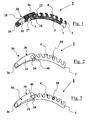
- the blocking device 1 comprises a first fixed rack 3, preferably made of aluminium and equipped with a longitudinal cavity 7 ( figure 6 ), in which a second mobile rack 5, preferably made of hardened steel, is housed ( figures 4, 5 and 6 ).
- the racks 3, 5 are toothed and define recesses 4 intended to contain the blocking pin 50 in different fastening positions.
- the racks 3, 5 are preferably curved and have the same bending radius at the respective toothings.
- the first rack 3 comprises a smooth portion 6 and a toothed portion 9 ( figure 6 ); some transversal through holes 12, 14 are formed.
- the through hole 12 has an elongated section, preferably elliptical.
- the teeth of the two racks 3, 5 are arranged side-by-side and they each have a different number: six for the rack 3 and five for the rack 5. Therefore, an end tooth of the rack 3 is not side-by-side with any tooth of the second rack 5 ( figure 1 ). In this way such an end tooth defines a recess 4 in which the blocking pin 50 can insert freely without opposition, both going in and coming out.
- the first rack 5 is constrained to the first rack 3 through an attachment pin 24 ( figures 1-3 and 6 ) with circular section slotted into the holes 12, 22.
- the (circular) section of the attachment pin 24 is less than and can be contained within that (slop or elliptical shaped) of the through hole 12 and this allows the pin 24 to translate inside the hole 12, in a direction roughly parallel to the toothings of the racks 3, 5, pulling the rack 5 into rotation with it.
- the blocking device 1 also comprises a pressing element 30, preferably a metallic slab that offers a flat upper actuation surface, shown in figure 6 . It has two slightly curved shoulders 32 and 34, arranged parallel to one another, and a flat joining portion 36 that extends roughly perpendicular between two of their ends.
- a pressing element 30 preferably a metallic slab that offers a flat upper actuation surface, shown in figure 6 . It has two slightly curved shoulders 32 and 34, arranged parallel to one another, and a flat joining portion 36 that extends roughly perpendicular between two of their ends.
- the pressing element or button 30 is mounted hinged to the rack 3 at the smooth portion 6 by means of a pin 26 that partially engages the hole 38, the hole 14 and the hole 42.
- the shoulders 32, 34 are arranged parallel to, and straddling, the rack 3.
- the pin 24 engages the hole 40, the hole 12, the hole 22 and the hole 44.
- the pressing element 30 can oscillate about the pin 26 by an angle defined by the clearance between the pin 24 and the holes 40, 44. Indeed, the pin 24 can translate inside the holes 40, 44 whereas it cannot translate inside the hole 22, consequently pulling the rack 5 into translation.
- the device 1 can be fixed to a flap of the opening of the boot through a rivet that passes through the hole 16.
- a further cavity 27 On the surface of the smooth portion 6 there is a further cavity 27, with axis substantially perpendicular to the curvature of the rack, which houses a spring 28.
- the spring 28 is in abutment at the top with the pressing element 30 and at the bottom on the base of the cavity 27, and it can be compressed following the element 30 being pressed.
- the user After having put on the boot, the user takes the fastening device equipped with the blocking pin 50 up to the blocking device 1 so as to be able to insert the blocking pin 50 into a recess 4.
- the mobile pin 24 is, consequently, at the lower end of the holes 40, 44 and, with respect to the rack 3, moved by the maximum amount towards its centre.
- the two racks 3, 5 have the respective toothed profile misaligned by the maximum amount, and this does not allow the blocking pin 50 to engage any recess 4.
- the pin 24 also pulls the rack 5 into translation, which moves towards the portion 6.
- the two racks 3, 5 have the respective toothed profile aligned, and this allows the blocking pin 50 to enter into, and engage, a recess 4.
- the user releases the pressing element 30.
- the spring 28 extends and the device goes back into the first configuration, in which the cooperation of the toothings of the racks 3, 5 allows the pin 50 to be held firmly in the recess 4.
- the holes 240, 244 also act as groove guides for the pin 24. This time the groove has, in its extension, a portion substantially perpendicular to the longitudinal extension of the rack elements 3, 5 that joins to a portion that is substantially arched or inclined with respect to the longitudinal extension of the rack elements 3, 5. Thus at the start of the oscillation the element 30 does not induce a translation of the pin 24, i.e. a "dead" zone is created.
- a blocking device 101 is shown in figures 9-13 , in which parts in common with the previous ones keep the same reference numerals. Different parts shall be indicated with a suffix '1'.
- a fixed rack 103 and a mobile rack 105 keep substantially the same configuration as the previous ones, in particular a longitudinal cavity in the fixed rack 103. Some particular embodiments, on the other hand, change.
- the pressing element 30 is not foreseen, and nor are attachment pins 24 and 26 foreseen.
- the rack 103 comprises a smooth portion 106 in which two through holes 112 are formed symmetrically that make the sides of the rack 103 communicate with the cavity 7.
- the hole 112 has an elongated section, preferably elliptical, and when the rack 105 is mounted in the cavity 7 it aligns with the holes 112.
- a through hole 122 is formed at a smooth portion 120 thereof adjacent to a toothed portion 121.
- a plate 130 supports and holds the rack 105 in position inside the cavity 7.
Landscapes
- Health & Medical Sciences (AREA)
- Dentistry (AREA)
- General Health & Medical Sciences (AREA)
- Oral & Maxillofacial Surgery (AREA)
- Transmission Devices (AREA)
Priority Applications (1)
| Application Number | Priority Date | Filing Date | Title |
|---|---|---|---|
| EP07425372A EP2002743A1 (fr) | 2007-06-14 | 2007-06-14 | Dispositif de blocage |
Applications Claiming Priority (1)
| Application Number | Priority Date | Filing Date | Title |
|---|---|---|---|
| EP07425372A EP2002743A1 (fr) | 2007-06-14 | 2007-06-14 | Dispositif de blocage |
Publications (1)
| Publication Number | Publication Date |
|---|---|
| EP2002743A1 true EP2002743A1 (fr) | 2008-12-17 |
Family
ID=38704812
Family Applications (1)
| Application Number | Title | Priority Date | Filing Date |
|---|---|---|---|
| EP07425372A Withdrawn EP2002743A1 (fr) | 2007-06-14 | 2007-06-14 | Dispositif de blocage |
Country Status (1)
| Country | Link |
|---|---|
| EP (1) | EP2002743A1 (fr) |
Cited By (2)
| Publication number | Priority date | Publication date | Assignee | Title |
|---|---|---|---|---|
| ITUD20080269A1 (it) * | 2008-12-22 | 2010-06-23 | Calzaturificio Dal Bello S R L | Dispositivo di chiusura per una calzatura sportiva quale uno scarpone da sci o simile |
| ITTV20100002A1 (it) * | 2010-01-15 | 2011-07-16 | Garmont S R L | Dispositivo di chiusura di calzature sportive |
Citations (6)
| Publication number | Priority date | Publication date | Assignee | Title |
|---|---|---|---|---|
| DE1869303U (de) * | 1963-01-21 | 1963-03-21 | Emeran Griesser | Skistiefel mit ristverschnuerung. |
| DE1942836U (de) * | 1966-04-16 | 1966-07-21 | Stocko Metallwarenfabriken Hug | Buegelverschluss, insbesondere fuer schuhwerk. |
| DE1961034U (de) * | 1963-05-04 | 1967-05-24 | Erna Strasser | Strammerverschluss fuer skischuhe. |
| US3521330A (en) * | 1967-07-31 | 1970-07-21 | Adalberto Sussman Steinberg | Toothed lever tension device particularly for mountain and ski-boots |
| EP0663155A1 (fr) | 1994-01-13 | 1995-07-19 | Lange International S.A. | Dispositif de fermeture d'une chaussure de ski |
| EP0766933A1 (fr) * | 1995-10-04 | 1997-04-09 | TECNICA SpA | Dispositif de fermeture pour chaussures de sport, en particulier chaussure de ski, avec éléments à prises extensibles |
-
2007
- 2007-06-14 EP EP07425372A patent/EP2002743A1/fr not_active Withdrawn
Patent Citations (6)
| Publication number | Priority date | Publication date | Assignee | Title |
|---|---|---|---|---|
| DE1869303U (de) * | 1963-01-21 | 1963-03-21 | Emeran Griesser | Skistiefel mit ristverschnuerung. |
| DE1961034U (de) * | 1963-05-04 | 1967-05-24 | Erna Strasser | Strammerverschluss fuer skischuhe. |
| DE1942836U (de) * | 1966-04-16 | 1966-07-21 | Stocko Metallwarenfabriken Hug | Buegelverschluss, insbesondere fuer schuhwerk. |
| US3521330A (en) * | 1967-07-31 | 1970-07-21 | Adalberto Sussman Steinberg | Toothed lever tension device particularly for mountain and ski-boots |
| EP0663155A1 (fr) | 1994-01-13 | 1995-07-19 | Lange International S.A. | Dispositif de fermeture d'une chaussure de ski |
| EP0766933A1 (fr) * | 1995-10-04 | 1997-04-09 | TECNICA SpA | Dispositif de fermeture pour chaussures de sport, en particulier chaussure de ski, avec éléments à prises extensibles |
Cited By (2)
| Publication number | Priority date | Publication date | Assignee | Title |
|---|---|---|---|---|
| ITUD20080269A1 (it) * | 2008-12-22 | 2010-06-23 | Calzaturificio Dal Bello S R L | Dispositivo di chiusura per una calzatura sportiva quale uno scarpone da sci o simile |
| ITTV20100002A1 (it) * | 2010-01-15 | 2011-07-16 | Garmont S R L | Dispositivo di chiusura di calzature sportive |
Similar Documents
| Publication | Publication Date | Title |
|---|---|---|
| CN111787825B (zh) | 具有调整手链长度的装置的手链扣 | |
| US8763210B2 (en) | Locking device for a buckle | |
| CN112293888B (zh) | 用于手表链的扣钩 | |
| EP1972225B1 (fr) | Curseur pour fermeture à glissière recto-verso avec dispositif de verrouillage automatique | |
| US7520036B1 (en) | Multi-point buckle for restraint system | |
| US4453290A (en) | Lever-operable fastener | |
| KR900007522Y1 (ko) | 버클 조립체 | |
| US4955633A (en) | Adjusting device for a ski binding | |
| RU2650915C9 (ru) | Застежка браслета, содержащая устройство для регулировки рабочей длины браслета | |
| US20080129015A1 (en) | Cross-Country or Telemark Binding | |
| US4546521A (en) | Fastener for sports shoes | |
| CA2780517C (fr) | Mecanisme de reliure a anneaux avec actionneur autobloquant | |
| US11583042B2 (en) | Bracelet with adjustable link for a watch or a piece of jewellery | |
| EP0220784A1 (fr) | Structure d'une boucle encliquetable pour la crémaillère du levier de fermeture, en particulier pour chaussures de ski | |
| RU2734124C1 (ru) | Опора багажника | |
| US20080023956A1 (en) | Fastening device for a ski skin | |
| US12433379B2 (en) | Device for adjusting the length of a wristlet | |
| EP2002743A1 (fr) | Dispositif de blocage | |
| EP3119486B1 (fr) | Mecanisme pour fixer longitudinalement une fixation sur une plaque de montage | |
| US3956796A (en) | Lacing device for ski boots | |
| US11173381B2 (en) | Front jaw | |
| EP3090641A1 (fr) | Chaussure de ski munie d'un mécanisme de sélection de parcours de ski-marche amélioré | |
| EP1859699A1 (fr) | Dispositif de fermeture, en particulier pour chaussure, avec crémaillère coulissante | |
| US7275757B2 (en) | Arrangement for longitudinal adjustment of two binding jaws of a ski binding | |
| US4264088A (en) | Slide mount for a ski binding component |
Legal Events
| Date | Code | Title | Description |
|---|---|---|---|
| PUAI | Public reference made under article 153(3) epc to a published international application that has entered the european phase |
Free format text: ORIGINAL CODE: 0009012 |
|
| AK | Designated contracting states |
Kind code of ref document: A1 Designated state(s): AT BE BG CH CY CZ DE DK EE ES FI FR GB GR HU IE IS IT LI LT LU LV MC MT NL PL PT RO SE SI SK TR |
|
| AX | Request for extension of the european patent |
Extension state: AL BA HR MK RS |
|
| 17P | Request for examination filed |
Effective date: 20090615 |
|
| RAP1 | Party data changed (applicant data changed or rights of an application transferred) |
Owner name: GARMONT S.R.L. |
|
| RIN1 | Information on inventor provided before grant (corrected) |
Inventor name: CHENET, ANTONIO |
|
| 17Q | First examination report despatched |
Effective date: 20090709 |
|
| AKX | Designation fees paid |
Designated state(s): AT BE BG CH CY CZ DE DK EE ES FI FR GB GR HU IE IS IT LI LT LU LV MC MT NL PL PT RO SE SI SK TR |
|
| RAP1 | Party data changed (applicant data changed or rights of an application transferred) |
Owner name: SCOTT SPORTS S.A. |
|
| STAA | Information on the status of an ep patent application or granted ep patent |
Free format text: STATUS: THE APPLICATION IS DEEMED TO BE WITHDRAWN |
|
| 18D | Application deemed to be withdrawn |
Effective date: 20150207 |