EP2002897B1 - Procédé et système de revêtement par pulvérisation pour corps de boîtes - Google Patents
Procédé et système de revêtement par pulvérisation pour corps de boîtes Download PDFInfo
- Publication number
- EP2002897B1 EP2002897B1 EP07252414A EP07252414A EP2002897B1 EP 2002897 B1 EP2002897 B1 EP 2002897B1 EP 07252414 A EP07252414 A EP 07252414A EP 07252414 A EP07252414 A EP 07252414A EP 2002897 B1 EP2002897 B1 EP 2002897B1
- Authority
- EP
- European Patent Office
- Prior art keywords
- powder
- bodies
- robotic arm
- cans
- booth
- Prior art date
- Legal status (The legal status is an assumption and is not a legal conclusion. Google has not performed a legal analysis and makes no representation as to the accuracy of the status listed.)
- Not-in-force
Links
Images


Classifications
-
- B—PERFORMING OPERATIONS; TRANSPORTING
- B05—SPRAYING OR ATOMISING IN GENERAL; APPLYING FLUENT MATERIALS TO SURFACES, IN GENERAL
- B05B—SPRAYING APPARATUS; ATOMISING APPARATUS; NOZZLES
- B05B13/00—Machines or plants for applying liquids or other fluent materials to surfaces of objects or other work by spraying, not covered by groups B05B1/00 - B05B11/00
- B05B13/06—Machines or plants for applying liquids or other fluent materials to surfaces of objects or other work by spraying, not covered by groups B05B1/00 - B05B11/00 specially designed for treating the inside of hollow bodies
- B05B13/0609—Machines or plants for applying liquids or other fluent materials to surfaces of objects or other work by spraying, not covered by groups B05B1/00 - B05B11/00 specially designed for treating the inside of hollow bodies the hollow bodies being automatically fed to, or removed from, the machine
-
- B—PERFORMING OPERATIONS; TRANSPORTING
- B05—SPRAYING OR ATOMISING IN GENERAL; APPLYING FLUENT MATERIALS TO SURFACES, IN GENERAL
- B05B—SPRAYING APPARATUS; ATOMISING APPARATUS; NOZZLES
- B05B13/00—Machines or plants for applying liquids or other fluent materials to surfaces of objects or other work by spraying, not covered by groups B05B1/00 - B05B11/00
- B05B13/02—Means for supporting work; Arrangement or mounting of spray heads; Adaptation or arrangement of means for feeding work
- B05B13/0221—Means for supporting work; Arrangement or mounting of spray heads; Adaptation or arrangement of means for feeding work characterised by the means for moving or conveying the objects or other work, e.g. conveyor belts
-
- B—PERFORMING OPERATIONS; TRANSPORTING
- B05—SPRAYING OR ATOMISING IN GENERAL; APPLYING FLUENT MATERIALS TO SURFACES, IN GENERAL
- B05B—SPRAYING APPARATUS; ATOMISING APPARATUS; NOZZLES
- B05B16/00—Spray booths
- B05B16/20—Arrangements for spraying in combination with other operations, e.g. drying; Arrangements enabling a combination of spraying operations
-
- B—PERFORMING OPERATIONS; TRANSPORTING
- B05—SPRAYING OR ATOMISING IN GENERAL; APPLYING FLUENT MATERIALS TO SURFACES, IN GENERAL
- B05B—SPRAYING APPARATUS; ATOMISING APPARATUS; NOZZLES
- B05B7/00—Spraying apparatus for discharge of liquids or other fluent materials from two or more sources, e.g. of liquid and air, of powder and gas
- B05B7/02—Spray pistols; Apparatus for discharge
- B05B7/08—Spray pistols; Apparatus for discharge with separate outlet orifices, e.g. to form parallel jets, i.e. the axis of the jets being parallel, to form intersecting jets, i.e. the axis of the jets converging but not necessarily intersecting at a point
- B05B7/0884—Spray pistols; Apparatus for discharge with separate outlet orifices, e.g. to form parallel jets, i.e. the axis of the jets being parallel, to form intersecting jets, i.e. the axis of the jets converging but not necessarily intersecting at a point the outlet orifices for jets constituted by a liquid or a mixture containing a liquid being aligned
-
- B—PERFORMING OPERATIONS; TRANSPORTING
- B05—SPRAYING OR ATOMISING IN GENERAL; APPLYING FLUENT MATERIALS TO SURFACES, IN GENERAL
- B05B—SPRAYING APPARATUS; ATOMISING APPARATUS; NOZZLES
- B05B7/00—Spraying apparatus for discharge of liquids or other fluent materials from two or more sources, e.g. of liquid and air, of powder and gas
- B05B7/14—Spraying apparatus for discharge of liquids or other fluent materials from two or more sources, e.g. of liquid and air, of powder and gas designed for spraying particulate materials
- B05B7/1481—Spray pistols or apparatus for discharging particulate material
- B05B7/1486—Spray pistols or apparatus for discharging particulate material for spraying particulate material in dry state
Definitions
- the invention relates generally to methods of manufacturing cans, and more particularly relates to a method system and both for coating a metal can with powder.
- Cans such as food cans and cans containing a beverage, are typically made from metals such as steel or aluminum alloy.
- can bodies are subject to a process in which a coating is applied to the interior of the can body.
- the interior coating is applied to the can body to protect the contents of the can from contamination or reaction with the can material, which can cause a change in the taste and/or color of the contents.
- An additional step of coating the exterior of the can body is also usually performed.
- the coating on the exterior of the container may be to protect the container from the environment (e.g., in the case of steel cans to inhibit formation of rust), and to supply a base for subsequent color printing.
- US 3, 989, 001 discloses a machine for spray-coating can exteriors.
- the cans are passed through a conveying system in single file where spray nozzles are sequentially operated to prevent coating material from passing between adjacent articles.
- the powders can be electrostatically charged in order to more reliably obtain adhesion of the powder to the can body. See for example Davidson et aL, US Patent 4,210,507 . Examples of powder compositions are disclosed in Pregmon, US Patent 3,882,064 ; Jung et al., US Patent 6,472,472 , and Srinivasan, US Patent 5,994,462 .
- the beverage can manufacturing industry has not adopted it widely. There are a variety of reasons for this, including difficulties in applying the technique at the speed required in high volume manufacturing plants, and the added costs for the powder coating equipment.
- the coatings applied to cans during manufacture are applied in the form of sprays which contain volatile organic chemicals.
- a more environmentally-friendly method and system for coating of can bodies using powder which avoids the use of volatile organic chemicals or release of such chemicals into the environment, but which is also cost efficient when applied in a mass production scenario.
- This disclosure provides for a method a system and a booth for environmentally friendly and cost efficient coating of cans during manufacturing with powder, which are particularly suitable for application in high volume can manufacturing plants such as plants operated by manufactures of aluminum beverage cans.
- the method is suitable for food and beverage cans in general, and in particular to aluminum beverage cans.
- the system of the invention is according to claim 1.
- the booth of the invention is according to claim 14.
- the method of the invention is according to claim 19.
- a system for powder coating of can bodies.
- the system includes a powder booth having an entrance and an exit.
- the powder booth includes at least one robotic arm and a plurality of powder application guns.
- the robotic arm is operable to move a plurality of can bodies as a group to a powder application zone where powder is applied to the interior and exterior of the can bodies by powder application guns.
- the system further includes a conveying system for receiving the can bodies as a group from the robotic arm.
- the system further includes an oven receiving the plurality of can bodies from the conveying system. The oven is operative to cure the powder that has been applied to the can bodies.
- the can bodies include a closed end portion, such as for example in the case of beverage cans the dome portion forming the bottom of the can body.
- the robotic arm operates to contact to the group of can bodies by means of vacuum applied by the robotic arm to the closed end portion of each of the can bodies. Once connected to the arm in this manner, the arm moves the cans as a group to the powder application zone and then to the conveyor system. Release of vacuum releases the group of can bodies from the arm and allows them to be placed onto the conveyor system. The arm moves back to pick up another group of cans. Then, powder is applied to the cans at the location of where the cans were attached by vacuum to the robotic arm.
- the system includes at least two robotic arms, each of which operates to successively move a plurality of can bodies as a group to the powder application zone and then to the conveyor system.
- one robotic arm holds one group of can bodies at the powder zone as powder is being applied to the can bodies, and then moves the can bodies to the conveyor system.
- the other robotic arm becomes connected to a new group of can bodies and then operates to move the new group to the powder application zone. Having two robotic arms operating in this manner serves to increase the throughput of the powder coating system.
- the robotic arm may further be constructed with a feature whereby the robotic arm operates to rotate each of the plurality of can bodies about each can's longitudinal axis while powder is being applied to the can bodies by the powder guns.
- an improved powder booth of a powder coating system for cans includes a robot arm operable to hold and transport a plurality of can bodies as a group within the powder booth, a first set of power guns operative to apply a powder to the exterior of the can bodies as the can bodies are held by the robotic arm, a second set of powder guns operative to apply a powder to the interior of the can bodies as the can bodies are held by the robotic arm, and a third set of powder guns operative to apply a powder to the location on the can bodies where the can bodies were held by the robotic arm.
- the booth includes a conveyor system receiving the plurality of can bodies from the robotic arm after application of powder from the first and second sets of powder guns.
- the third set of powder guns is operative to spray powder onto the can bodies after the can bodies have been deposited onto the conveyor system by the robotic arm.
- the robotic arm travels back and forth to deposit the cans onto the conveyor in a linear direction.
- the direction of movement of the conveying system is substantially perpendicular to the linear direction of travel of the robotic arm. This feature allows for narrow spacing for the groups of cans after they are placed onto the conveying system.
- a method of powder coating of can bodies includes the steps of: a) moving a plurality of can bodies to a location exterior of a powder booth; b) moving the plurality of can bodies as a group into the powder booth and to a powder application zone within the powder booth; c) applying a powder to the' can bodies; d) moving the group of can bodies to a conveyor system; and e) applying additional powder to the group of can bodies after placement of the can bodies on the conveyor system.
- the method further includes the step of f) moving the group of can bodies from the powder booth to an oven for curing of the powder applied to the can bodies.
- Step c) of the method may optionally include the additional step of rotating each of the cans of the group about an axis.
- step a) the cans are placed in the location exterior to the powder. booth in a predetermined configuration matching a configuration of the robotic arm. While various configurations are possible, in one embodiment the configuration is in the form of rows and columns of can bodies, and wherein there are two columns and N rows, and wherein N is greater than or equal to two. One specific example, N is greater than 10, such as for example 16. In this arrangement, the robotic arm operates to lift 32 cans simultaneously as a group and carry the cans to the powder coating zone and then to the conveyor system.
- a method of continuous powder coating of can bodies including the steps of a) providing a set of can bodies at a location exterior of a powder booth in a predetermined configuration; b) moving a robotic arm to the location, connecting the set of can bodies to the robotic arm and moving the robotic arm and connected can bodies into the powder booth; c) while holding the set of can bodies with the robotic arm, applying a powder to the can bodies within the powder booth; d) releasing the group of can bodies from the robotic arm; e) applying additional powder to the group of can bodies at the location where the can bodies where connected to the robotic arm, and f) repeating steps a), b), c), d) and e).
- Figure 1 is a plan view of a system 10 for continuous powder coating of can bodies 12.
- the system 10 includes a powder booth 14 having an entrance 16 and an exit 18.
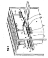
- the powder booth is shown in more detail in plan view in Figure 2 and in a perspective view in Figures 5 and 6 .
- the can bodies 12 could be any food or beverage can.
- a beverage can body is shown in perspective view in Figure 7 .
- the can body includes an interior surface 30, a top rim or "cut edge" 31, an exterior surface 32, a closed end 34, which, in this example, has an inwardly domed shape as found on common beverage cans, and a longitudinal axis 36.
- the interior, and exterior surfaces 30 and 32 are powder coated in the system of Figure 1 prior to necking and flanging the can body 12.
- the can forming, powder coating, necking and flanging occur within one continuous manufacturing process.
- the powder coating system of Figure 1 may be installed in a plant where the cans 12 are manufactured. In order to contain the powder and prevent it from spreading in the plant, the powder coating occurs in a powder booth 14 as shown in Figure 1 .
- the powder booth 14 includes at least one robotic arm 20 shown best in Figure 5 and a plurality of powder application guns 22.
- the guns 22 are arranged in several sets, including a first set 24 which applies powder to the exterior of the cans, a second set 26 which applies powder to the interior of the cans, and a third set 28 ( Figure 5 ) which applies powder to the closed end of the can bodies 12, namely the portion of the can body that was held by the robotic arm 20 during the interior and exterior coating step.
- the robotic arm 20 operates to move a plurality of can bodies 12 as a group 40 into the powder booth 14 and to a powder application zone 42 ( Figure 1A ) in the booth where powder is applied to the interior and exterior of the can bodies by the powder application guns 22.
- the system of Figure 1 can include more than one arm 20, and in the illustrated embodiment of Figures 5 and 6 includes two arms 20 each operable independent of the other to connect to a group of can bodies 12 exterior of the powder booth, carry them into and through the booth for coating and to a conveying system 50 and deposit the cans onto a conveyor of 64 the conveying system.
- the arms 20 are timed so that as one arm is holding one group or set of can bodies in the powder coating zone and carrying that group to the conveyor system 50 the other arm is moved to the loading zone external of the powder booth to connect to the next group 40 of can bodies and carry them into the powder booth.
- the robotic arm 20 connects to each of the can bodies by means of suction applied to the closed end portion of the can bodies.
- the robotic arm further includes features for rotating the cans about the longitudinal axis 36 while being held by suction, such that the interior and exterior powder coating is evenly applied to all the surfaces of the can body.
- the conveying system 50 receives a plurality of can bodies 12 as a group from the robotic arm 20 after application of the powder to the can bodies by the powder application guns 24 and 26.
- a third set of powder guns 28 ( Figure 5 ) is provided above the conveyor system 50 which operates to apply powder to the portion of the can bodies which were held by the robotic arm, namely the closed end or dome 34 of the can bodies in this example.
- the cans are placed "dome up'' on the feed conveyor belt, held “dome up” by the arm 20, and placed “dome up” on the belt 64 of the conveying system 50.
- the arms are placed on the belt 64 in a zone 54 ( Figure 1A ) where the dome powder guns 28 are located.
- the conveying system 50 then conveys the cans to an oven 60.
- the oven is equipped with servo-driven fans and thermal heating zones and operates to cure the powder applied to the can bodies. After passing through the oven 60, the cans are carried to downstream processing locations, such as can necking station for necking the can body.
- a functional diagram of the powder system 10 of Figure 1 is shown in Figure 1A .
- a feed conveyor 62 supplies groups of cans "dome up" in a predetermined configuration to a loading zone external of the powder booth 14 adjacent to the entrance 16.
- An arm 20 (not shown in Figure 1A ) picks up the group of cans 40 and carries them to the exterior and interior powder coat zone 42 where the exterior and interior surfaces of the cans in the group 40 are coated with powder.
- the arm the carries the group 40 of cans to the conveyor 64 and deposits the group of cans onto the conveyor 64, dome up, a the dome coat zone 54.
- a set of spray guns 28 ( Figure 5 ) moves horizontally over the cans deposited on the belt 64 and sprays the domes of the cans.
- the cans are then carried through the exit 18 of the powder booth 14 where they are placed on a cleaning and powder recovery belt 66.
- the belt includes two powder recovery suction zones 70A and 70B, where excess powder is recovered from the belt.
- the conveyor 66 carries the cans to the oven 60, or as shown in Figure 1 , to a separate oven conveyor 68.
- the cans are advanced through the oven 60 where the powder is cured.
- the cured, coated cans then exit out of the oven and are subject to downstream processing steps, such as necking, flanging, and color printing.
- the system 10 is designed such that powder is applied to cans on both the inside and the outside (inclusive dome and chime) in one application station (powder booth) and only one curing station (oven).
- the speed for one application of powder to the cans can reach between 400 - 600 cans per minute in the illustrated embodiment.
- the coating weight for powder coatings is low (2g/ 50ml Can) and applied in a narrow coaling tolerance, with maximum thickness variation on coated cans between 10 and 15 microns, for example.
- the illustrated embodiment and method of operation produces a coated aluminum beverage can, which compared to prior art approaches, eliminates 4 processes stations, and replace such stations with one station - powder booth 14.
- the inventive system and method of operation eliminates five process stations and replaces them with one station. Consequently, the methods and system of this invention presents an attractive option in terms of capital and operation costs as compared to prior an coating methods.
- the powder booth 14 will be described further in conjunction with Figures 1-6 .
- the powder booth 14 includes guns 22 and 28 which supplied are supplied with a powder, preferably subject to electrostatic charge, from a powder source 90 via a supply conduit 92, shown in Figure 2 .
- the powder may be any suitable powder for powder coating purposes, such as disclosed in Pregmon, US Patent 3,882,064 ; Jung et al., US Patent 6,472,472 , and Srinivasan, US Patent 5,994,462 .
- the nature, color, composition or characteristics of the powder are not considered particularly critical and these and other powder compositions either now known or later developed may be used.
- suitable powders are pure polyester powders, pure epoxy powders, and hybrids of polyester and epoxy.
- any color of direct food contact approved powders can be used, including white or dear powders.
- white or dear powders can be used for internal and external application.
- the powder application guns 22, 28 are conventional in design and may take the form of powder guns described in the patent and technical literature.
- the guns preferably are designed so as to not disturb the electrostatic charge applied to the powder while the exterior and interior surfaces of the cans are sprayed with powder simultaneously at the exterior and interior coat zone 42 of the powder booth.
- each arm 20 is suspended from a track 102 extending the length of the powder booth.
- the tracks include a portion 104 which allow the arms to move laterally and out of the way to allow the other arm to pick up new group of cans 40 or deposit the group of cans 40 onto the belt 64.
- each arm 40 is operable to hold and transport a plurality of can bodies as a group 40 within the powder booth 14. The operate in a fashion such that they alternate to transport groups of can bodies to the location of the first and second set of powder guns 24 and 26 for exterior and interior coating and depositing the groups of cans onto the belt 64.
- the tracks 102 are arranged such that the robot arm moves exterior of the entrance to the powder booth to pick up a plurality of cans as a group 40 (see Figure 6 ) and move them through the entrance 16 of the powder booth to the powder application zone (location of sets of guns 24 and 26) and from the powder application zone to the conveyor 64 of the conveyor system 50.
- a third arm 106 carrying the dome spray guns 28 moves laterally over the cans 40 and spray coats the domes of the cans.
- the arms 20 are constructed with a plurality of vacuum chucks (suction elements) 108 (see Figures 5 and 6 ). Referring to Figure 6 , when the arms 20 are lowered onto the group of cans 40 on the feed conveyor 62, the vacuum chucks 108 make contact with the domes of the cans, and vacuum is applied to the elements 108 which allow the cans to be retained to the arm when the arm lifts the cans off the conveyor 62 and carry them into the powder booth. Additionally, the arms include an internal mechanical arrangement (not shown) which operates to rotate each of the can bodies about the longitudinal axis 36 ( Figure 7 ) while powder is being applied to the can bodies by the powder guns 24 and 26, insuring an even coating of powder to the cans 12. A suitable rotation rate is 20 RPM but of course this can vary as desired.
- the cans placed on the feed conveyor 62 are arranged in a predetermined configuration matching the configuration of the robotic arm.
- the configuration can be rows and columns of cans.
- the configuration is two columns of cans and N rows, and wherein N is greater than or equal to two. N may be greater than 10, such as 16.
- Other configurations are possible such as a clusters of cans, each cluster in a circular arrangement or otherwise.
- the system 10 includes a conveying system 50 which serves to advance the cans through and out of the powder booth 14 and into and through the oven 60.
- the conveying system 50 in the illustrated embodiment includes several different belts to accomplish, these functions.
- Belt or matt 64 receives the groups of cans from the arms 40.
- the belt 64 is a perforated metal matt in the illustrated embodiment. Powder recovery may occur below the belt 64.
- the arms 20 travel in a generally a linear direction (as dictated by the tracks 102 of Figure 2 and 3 ), and the direction of movement of the conveying system 50 including the belt 64 is substantially perpendicular to the linear direction of travel of the robotic arm.
- This feature allows the cans to be closely stacked by the arm, see for example the arrangement of the cans on the belt 64 in Figure 2 .
- FIG. 2 after the cans have been conveyed out of the powder booth they are transferred onto a second, perforated cleaning belt 66. At least one suction zone is provided proximate to the conveying system belt 55 wherein excess powder is recovered from the can bodies after the can bodies have been applied with powder at the powder application zones 42 and 54. In the illustrated embodiment, are two such suction zones shown at 70A and 70B in Figure 1A .
- Belt 66 may be made from Teflon or include a Teflon coating.
- the conveyor system also preferably includes a third component, shown as belt 68 in Figure 2 , which receives the cans from belt 66 and carries the cans through the oven 60.
- the belt is also a perforated belt
- the electrical melting/curing oven 60 contains 3 heating zones (approx. 40kw each) and 1 cooling zone.
- the fan motors (not shown) are servo driven and the exhaust speed can be adjusted independently (to avoid spoilage from falling cans.
- the length of the oven will depend on such factors as the melting temperatures and curing times of powders to be used, and speed of the belt 68. An ideal powder only needs a 12m oven with two 36kw heating zones.
- the temperature of the oven will vary depending on the powder used and may be between 180° C. and 220° C., ideally the temperature is as low as possible to reduce energy consumption for the system.
- the curing time for curing the powder will depend on the powder composition. Representative times are between 2 and 10 minutes.
- a matt cleaner is installed at the end of the oven for cleaning the belt 68.
- a group 40 of two rows of sixteen cans each is delivered "dome-up" outside the powder booth 14 on the feed conveyor 62, the cans resting on their cut edge 31. Then the cans are picked up by the powder application robot arm 20. In particular, the robot arm 20 lowers down and picks up the thirty two cans (with ' vacuum applied at the vacuum chucks 108) simultaneously at the dome 34 of the cans.
- the cans are moved at high speed upward and horizontal to the application position or exterior and interior coat zone 42.
- the robot arm triggers the external application guns 24 and moves the cans vertically downwards towards the interior application guns 26, during this operation the external powder is applied by the guns 24.
- the robot arm stops for 30ms..
- the cans are moved by the robot arm with high speed to the dome application matt or belt 64. During this movement the cans stop rotating. All thirty-two cans are placed simultaneously on the perforated metal matt 64, "dome up". The metal matt 64 is grounded to maintain an electrostatic potential between the cans placed on the matt and the charged powder applied by the dome spray guns 28 of Figure 6 .
- the perforated matt 64 moves the cans 90° sideways form the robot movement; this allows narrow spacing between the cans.
- the dome application spraying is done with guns 28 ( Figure 6 ) spraying a continuous haze of powder onto the can domes.
- the guns are mounted to an arm 106 which moves laterally over the cans to apply the powder to the domes.
- a suction slit for powder recovery is placed at the end the metal belt 64; the end of the metal belt 64 is just outside the powder booth as shown in Figures 5 and 6 .
- This belt 66 contains two strong powder recovery suction zones 70A and 70B ( Figure 1A ), one (70B) at the beginning of the belt, and one (70A) at the end of the belt where the final powder residue is collected and recovered.
- the cans are transferred onto the perforated Teflon oven belt 68 ( Figure 2 ), still dome up.
- a perforated belt is used for the oven belt 68 to avoid condensate remains inside the cans.
- the belt 68 advances the cans as a group through the oven 60 where the powder is cured.
- the cans are then transferred to downstream processing locations.
- the downstream processing details are not important and will vary depending on the type of can.
Landscapes
- Application Of Or Painting With Fluid Materials (AREA)
- Spray Control Apparatus (AREA)
Claims (31)
- Système (10) de revêtement par pulvérisation des corps de boîte (12) comprenant :une cabine de pulvérisation (14) ayant une entrée (16) et une sortie (18), la cabine de pulvérisation comprenant au moins un bras robotisé (20) et une pluralité de pistolets d'application de pulvérisation (22), le au moins un bras robotisé pouvant fonctionner pour déplacer une pluralité de corps de boîte sous la forme d'un groupe (40) jusqu'à une zone d'application de pulvérisation (42) dans laquelle la pulvérisation est appliquée sur l'intérieur et l'extérieur de la pluralité de corps de boîte par la pluralité de pistolets d'application de pulvérisation ;un système de convoyeur (50) pour recevoir la pluralité de corps de boîte sous la forme d'un groupe à partir du au moins un bras robotisé ; etun four (60) recevant la pluralité de corps de boîte du système de convoyeur et fonctionnant pour faire sécher la pulvérisation appliquée sur la pluralité de corps de boîte.
- Système (10) selon la revendication 1, dans lequel les corps de boîte (12) comprennent une partie d'extrémité fermée (34) et dans lequel le au moins un bras robotisé (20) se raccorde à la pluralité de corps de boîte au moyen de l'aspiration appliquée sur la partie d'extrémité fermée de chacun des corps de boîte.
- Système (10) selon la revendication 2, dans lequel la cabine de pulvérisation (14) comprend en outre une zone (54) dans laquelle la pulvérisation est appliquée sur la partie d'extrémité fermée (34) des corps de boîte (12) après que les corps de boîte aient été libérés du bras robotisé (20) sur le système de convoyeur (50).
- Système (10) selon la revendication 1, dans lequel le système comprend en outre au moins une zone d'aspiration (70A, 70B) à proximité du système de convoyeur (50), dans lequel la pulvérisation en excès est récupérée des corps de boîte (12) après que les corps de boîte aient été appliqués avec la pulvérisation au niveau de la zone d'application de pulvérisation (42).
- Système (10) selon la revendication 1, dans lequel le système comprend au moins deux bras robotisés (20), dont chacun fonctionne pour déplacer une pluralité de corps de boîte (12) sous la forme d'un groupe (40) vers la zone d'application de pulvérisation (42) et ensuite vers le système de convoyeur (50).
- Système (10) selon la revendication 1, dans lequel le système de convoyeur (50) comprend un premier composant comprenant une courroie perforée (64) recevant le groupe (40) de boîtes (12) du au moins un bras robotisé (20), dans lequel le bras robotisé se déplace dans une direction linéaire, et dans lequel la direction de déplacement du premier composant du système de convoyeur est sensiblement perpendiculaire à la direction linéaire de déplacement du bras robotisé.
- Système (10) selon la revendication 6, dans lequel le système de convoyeur (50) comprend un deuxième composant comprenant une courroie de nettoyage perforée (66) ayant des zones d'aspiration de récupération de pulvérisation (70A, 70B), le second composant recevant le groupe (40) de corps de boîte (12) du premier composant et un troisième composant comprenant un convoyeur (68) pour transporter les corps de boîte dans le four (60).
- Système (10) selon la revendication 7, dans lequel le convoyeur (68) transportant les corps de boîte (12) dans le four (60) comprend une courroie perforée.
- Système (10) selon la revendication 1, dans lequel le au moins un bras robotisé (20) se déplace à l'extérieur de l'entrée (16) vers la cabine de pulvérisation (14) pour prélever une pluralité de boîtes (12) sous la forme d'un groupe (40) et les déplace en passant par l'entrée de la cabine de pulvérisation vers la zone d'application de pulvérisation (42) et de la zone d'application de pulvérisation au système de convoyeur (50).
- Système (10) selon la revendication 1, dans lequel le au moins un bras robotisé (20) fonctionne pour faire tourner chacun de la pluralité de corps de boîte (12) alors que la pulvérisation est appliquée sur les corps de boîte par les pistolets de pulvérisation (22) .
- Système (10) selon la revendication 1, dans lequel la pluralité de pistolets d'application de pulvérisation (22) comprend :un premier ensemble (24) de pistolets de pulvérisation, opérationnel pour appliquer une pulvérisation sur l'extérieur de la pluralité de corps de boîte (12) lorsque la pluralité de corps de boîte est maintenue par le au moins un bras robotisé (20) ;un deuxième ensemble (26) de pistolets de pulvérisation, opérationnel pour appliquer une pulvérisation sur l'extérieur de la pluralité de corps de boîte ; etun troisième ensemble (28) de pistolets de pulvérisation, opérationnel pour appliquer une pulvérisation à l'emplacement de la pluralité de corps de boîte lorsque la pluralité de corps de boîte est maintenue par le au moins un bras robotisé.
- Système (10) selon la revendication 11, dans lequel le système de convoyeur (50) est prévu pour recevoir la pluralité de corps de boîte (12) du bras robotisé (20) après l'application de la pulvérisation sur les corps de boîte par les premier (24) et deuxième (26) ensembles de pistolets de pulvérisation.
- Système (10) selon la revendication 12, dans lequel la cabine de pulvérisation (14) comprend en outre un second bras robotisé (20), le second bras robotisé pouvant fonctionner pour maintenir et transporter une pluralité de corps de boîte (12) sous la forme d'un groupe (40) à l'intérieur de la cabine de pulvérisation et dans lequel les premier et second bras alternent pour transporter des groupes de corps de boîte à l'emplacement des premier (24) et deuxième (26) ensembles de pistolets de pulvérisation.
- Cabine de pulvérisation (14) pour un système de revêtement par pulvérisation (10) pour des boîtes, comprenant :un bras robotisé (20) pouvant fonctionner pour maintenir et transporter une pluralité de corps de boîte (12) sous la forme d'un groupe (40) à l'intérieur de la cabine de pulvérisation ;un premier ensemble (24) de pistolets de pulvérisation pour appliquer une pulvérisation sur l'extérieur de la pluralité de corps de boîte lorsque la pluralité de corps de boîte est maintenue par le bras robotisé ;un deuxième ensemble (26) de pistolets de pulvérisation pour appliquer une pulvérisation à l'intérieur de la pluralité de corps de boîte ; etun troisième ensemble (28) de pistolets de pulvérisation pour appliquer une pulvérisation sur l'emplacement de la pluralité de corps de boîte lorsque la pluralité de corps de boîte est maintenue par le bras robotisé.
- Cabine de pulvérisation (14) selon la revendication 14, comprenant en outre :un système de convoyeur (50) recevant la pluralité de corps de boîte (12) du bras robotisé (20) après l'application de la pulvérisation sur les corps de boîte par les premier et deuxième (24, 26) ensembles de pistolets de pulvérisation.
- Cabine de pulvérisation (14) selon la revendication 15, dans laquelle le bras robotisé (20) se déplace dans une direction linéaire et dans laquelle la direction de déplacement du système de convoyeur (50) est sensiblement perpendiculaire à la direction linéaire de déplacement du bras robotisé.
- Cabine de pulvérisation (14) selon la revendication 15, dans laquelle le système de convoyeur comprend une courroie perforée (64).
- Cabine de pulvérisation (14) selon la revendication 15, dans laquelle la cabine de pulvérisation comprend en outre un second bras robotisé (20), le second bras robotisé pouvant fonctionner pour maintenir et transporter une pluralité de corps de boîte (12) sous la forme d'un groupe (40) à l'intérieur de la cabine de pulvérisation et dans laquelle les premier et second bras alternent pour transporter les groupes de corps de boîte vers l'emplacement des premier et deuxième (24, 26) ensembles de pistolets de pulvérisation.
- Procédé pour appliquer un revêtement par pulvérisation sur des corps de boîte (12), comprenant les étapes consistant à :a) déplacer une pluralité de corps de boîte vers un emplacement à l'extérieur d'une cabine de pulvérisation (14) ;b) déplacer la pluralité de corps de boîte sous la forme d'un groupe (40) dans la cabine de pulvérisation et vers une zone d'application de pulvérisation (42) à l'intérieur de la cabine de pulvérisation ;c) appliquer une pulvérisation sur les corps de boîte ;d) déplacer le groupe de corps de boîte vers un système de convoyeur (50) ; ete) appliquer une pulvérisation supplémentaire sur le groupe de corps de boîte après la mise en place des corps de boîte sur le système de convoyeur.
- Procédé selon la revendication 19, comprenant en outre l'étape consistant à :f) déplacer le groupe (40) de corps de boîte (12) de la cabine de pulvérisation (14) vers un four (60) pour faire sécher la pulvérisation appliquée sur les corps de boîte.
- Procédé selon la revendication 19, dans lequel pendant l'étape c), réaliser l'étape supplémentaire consistant à faire tourner chacune des boîtes (12) du groupe (40) autour d'un axe.
- Procédé selon la revendication 19, dans lequel les boîtes (12) comprennent des canettes de boisson ayant une partie de dôme fermant une extrémité de la boîte et pendant les étapes b), c) et d), le groupe (40) de boîtes est maintenu par un bras robotisé (20) au moyen de l'aspiration appliquée par le bras robotisé sur la partie de dôme de la boîte.
- Procédé selon la revendication 22, dans lequel à l'étape a), les boîtes (12) sont placées dans l'emplacement à l'extérieur de la cabine de pulvérisation (14) dans une configuration prédéterminée correspondant à une configuration du bras robotisé (20) .
- Procédé selon la revendication 23, dans lequel la configuration prédéterminée comprend une configuration de rangées et de colonnes de boîtes (12) dans lequel on trouve deux colonnes et N rangées, et dans lequel N est supérieur ou égal à deux.
- Procédé selon la revendication 24, dans lequel N est supérieur à 10.
- Procédé selon la revendication 19, dans lequel l'étape a) comprend l'étape consistant à prévoir un ensemble de corps de boîte (12) à un emplacement à l'extérieur de la cabine de pulvérisation (14) dans une configuration prédéterminée,
l'étape b) comprend les étapes consistant à déplacer un bras robotisé (20) vers l'emplacement raccordant le bras robotisé à l'ensemble de corps de boîte (12), et déplacer le bras robotisé et raccorder les corps de boîte dans la cabine de pulvérisation ;
l'étape c) comprend tout en maintenant l'ensemble de corps de boîte avec le bras robotisé, l'étape consistant à appliquer une pulvérisation sur les corps de boîte à l'intérieur de la cabine de pulvérisation ;
l'étape d) comprend en outre l'étape consistant à libérer le groupe de corps de boîte du bras robotisé ;
l'étape e) comprend l'étape consistant à appliquer une pulvérisation supplémentaire sur le groupe de corps de boîte à l'emplacement où les corps de boîte sont raccordés au bras robotisé, et dans lequel le procédé comprend en outre l'étape f) consistant à répéter les étapes a), b), c), d) et e) comme ci-dessus. - Procédé selon la revendication 26, dans lequel la configuration prédéterminée comprend une configuration de rangées et de colonnes de boîtes (12), dans lequel on trouve deux colonnes et N rangées et dans lequel N est supérieur ou égal à deux.
- Procédé selon la revendication 27, dans lequel N est supérieur à 10.
- Procédé selon la revendication 26, dans lequel les corps de boîte (12) ont des surfaces intérieure et extérieure et dans lequel à l'étape c) la pulvérisation est appliquée sur les surfaces intérieure et extérieure.
- Procédé selon la revendication 19, dans lequel les corps de boîte (12) comprennent des corps de canette de boisson.
- Procédé selon la revendication 26, dans lequel les corps de boîte (12) comprennent des corps de canette de boisson.
Priority Applications (5)
| Application Number | Priority Date | Filing Date | Title |
|---|---|---|---|
| ES07252414T ES2340728T3 (es) | 2007-06-14 | 2007-06-14 | Metodo y sistema de recubrimiento por pulverizacion para cuerpos de lata. |
| AT07252414T ATE455599T1 (de) | 2007-06-14 | 2007-06-14 | System und verfahren zur pulverbeschichtung von behälterkörpern |
| EP07252414A EP2002897B1 (fr) | 2007-06-14 | 2007-06-14 | Procédé et système de revêtement par pulvérisation pour corps de boîtes |
| DE602007004462T DE602007004462D1 (de) | 2007-06-14 | 2007-06-14 | System und Verfahren zur Pulverbeschichtung von Behälterkörpern |
| PCT/GB2008/002057 WO2008152409A1 (fr) | 2007-06-14 | 2008-06-13 | Procédé de revêtement par poudre et système pour boîtes métalliques |
Applications Claiming Priority (1)
| Application Number | Priority Date | Filing Date | Title |
|---|---|---|---|
| EP07252414A EP2002897B1 (fr) | 2007-06-14 | 2007-06-14 | Procédé et système de revêtement par pulvérisation pour corps de boîtes |
Publications (2)
| Publication Number | Publication Date |
|---|---|
| EP2002897A1 EP2002897A1 (fr) | 2008-12-17 |
| EP2002897B1 true EP2002897B1 (fr) | 2010-01-20 |
Family
ID=38537844
Family Applications (1)
| Application Number | Title | Priority Date | Filing Date |
|---|---|---|---|
| EP07252414A Not-in-force EP2002897B1 (fr) | 2007-06-14 | 2007-06-14 | Procédé et système de revêtement par pulvérisation pour corps de boîtes |
Country Status (5)
| Country | Link |
|---|---|
| EP (1) | EP2002897B1 (fr) |
| AT (1) | ATE455599T1 (fr) |
| DE (1) | DE602007004462D1 (fr) |
| ES (1) | ES2340728T3 (fr) |
| WO (1) | WO2008152409A1 (fr) |
Families Citing this family (9)
| Publication number | Priority date | Publication date | Assignee | Title |
|---|---|---|---|---|
| ITMI20121358A1 (it) * | 2012-08-01 | 2014-02-02 | Tapematic Spa | Macchina per la verniciatura e linea per la finitura di oggetti tridimensionali di piccole dimensioni e relativi metodi |
| WO2014108242A1 (fr) * | 2013-01-08 | 2014-07-17 | Aygaz Anonim Sirketi | Système de peinture de cylindres |
| CN105268580B (zh) * | 2015-10-23 | 2018-04-10 | 浙江绿健胶囊有限公司 | 一种空心胶囊囊坯自动喷油装置 |
| CN107930944B (zh) * | 2017-12-18 | 2021-01-15 | 佛山市鼎翘五金有限公司 | 一种多金属管表面同步喷烤漆一体箱 |
| CN109351516A (zh) * | 2018-09-29 | 2019-02-19 | 柳州市恒茂木业有限公司 | 一种木业板材用阻燃漆喷涂装置 |
| CN110743734B (zh) * | 2019-11-28 | 2020-12-15 | 阳信东泰精密金属有限公司 | 一种铝型材喷涂系统 |
| CN111250304A (zh) * | 2020-03-18 | 2020-06-09 | 方永东 | 一种保温杯自动化喷涂装置 |
| CN113560076B (zh) * | 2021-08-06 | 2022-06-24 | 广州城建职业学院 | 一种绿色环保建筑材料表面喷漆设备 |
| CN120815674B (zh) * | 2025-09-19 | 2025-12-26 | 南通四方罐式储运设备制造有限公司 | 罐式集装箱粉末喷涂生产线的工艺布局结构及作业方法 |
Family Cites Families (13)
| Publication number | Priority date | Publication date | Assignee | Title |
|---|---|---|---|---|
| US3989001A (en) | 1966-12-16 | 1976-11-02 | Continental Can Company, Inc. | Machine for spray-coating can body exteriors |
| US3952698A (en) * | 1973-09-27 | 1976-04-27 | Kaiser Aluminum & Chemical Corporation | Can treating system |
| US4180844A (en) | 1976-04-01 | 1979-12-25 | Coors Container Company | Powder spray apparatus and method for coating interior surface of containers |
| US4094760A (en) | 1977-07-25 | 1978-06-13 | Aluminum Company Of America | Method and apparatus for differentially and simultaneously electrocoating the interior and exterior of a metal container |
| US4291640A (en) | 1977-09-09 | 1981-09-29 | The Continental Group, Inc. | Powder coating apparatus for two-piece cans |
| US4210507A (en) | 1978-09-18 | 1980-07-01 | Aluminum Company Of America | Electrocoating flow control electrode and method |
| USRE33482E (en) | 1984-06-21 | 1990-12-11 | Nordson Corporation | Adjustable powder spray gun |
| US4987001A (en) | 1989-02-09 | 1991-01-22 | Nordson Corporation | Method and apparatus for coating the interior surface of hollow, tubular articles |
| GB2259756B (en) * | 1991-09-11 | 1996-01-10 | Daiwa Can Co Ltd | Method and apparatus for drying containers |
| JP2754300B2 (ja) * | 1991-12-06 | 1998-05-20 | 大和製罐株式会社 | Di缶表面処理方法およびその装置 |
| US5474609A (en) | 1992-06-30 | 1995-12-12 | Nordson Corporation | Methods and apparatus for applying powder to workpieces |
| US5725670A (en) | 1994-02-18 | 1998-03-10 | Nordson Corporation | Apparatus for powder coating welded cans |
| DE59610063D1 (de) | 1995-05-12 | 2003-02-27 | Elpatronic Ag Bergdietikon | Verfahren und Vorrichtung zur Innenbeschichtung von Behälterzargen |
-
2007
- 2007-06-14 EP EP07252414A patent/EP2002897B1/fr not_active Not-in-force
- 2007-06-14 DE DE602007004462T patent/DE602007004462D1/de active Active
- 2007-06-14 AT AT07252414T patent/ATE455599T1/de not_active IP Right Cessation
- 2007-06-14 ES ES07252414T patent/ES2340728T3/es active Active
-
2008
- 2008-06-13 WO PCT/GB2008/002057 patent/WO2008152409A1/fr not_active Ceased
Also Published As
| Publication number | Publication date |
|---|---|
| ATE455599T1 (de) | 2010-02-15 |
| ES2340728T3 (es) | 2010-06-08 |
| WO2008152409A1 (fr) | 2008-12-18 |
| EP2002897A1 (fr) | 2008-12-17 |
| DE602007004462D1 (de) | 2010-03-11 |
Similar Documents
| Publication | Publication Date | Title |
|---|---|---|
| EP2002897B1 (fr) | Procédé et système de revêtement par pulvérisation pour corps de boîtes | |
| EP2692450B1 (fr) | Machine pour peindre petits, tridimensionnels objets et méthode | |
| US8846155B2 (en) | Coating method and associated coating device | |
| CN102665931B (zh) | 用于物体的表面处理的设备 | |
| US6319563B1 (en) | Golf ball painting method | |
| US20180117615A1 (en) | Continuous vertical spraying of bodies such as cans | |
| CA2231469C (fr) | Installation de traitement de contenants, dispositif pour transporter ces contenants et palettes pour ces contenants | |
| CA1142813A (fr) | Methode et dispositif pour le peinturage simultane de plusieurs pieces | |
| CN1397070A (zh) | 制造dvd的方法和装置 | |
| CN113924170A (zh) | 用于在大体平坦的部件上施用涂料的设备 | |
| EP0646418B1 (fr) | Système de revêtement entièrement automatique pour revêtir différents types d'objets produits en faibles quantités | |
| EP1524061A3 (fr) | Dispositif de revêtement à arc plasma avec une unité locale ayant un anneau avec des passages pour fluides et pröcédés à arc plasma pour réaliser des revêtements à faible teneur en oxydes | |
| EP2500448B1 (fr) | Dispositif et méthode pour la métallisation de pièces tridimensionelles de taille petite | |
| WO2012089789A1 (fr) | Cabine de peinture destinée à des installations de peinture pour des produits | |
| PL184564B1 (pl) | Zestaw urządzeń do natryskowego powlekania przedmiotów farbą | |
| CN107744903A (zh) | 达克罗涂装、烘干一体化装置 | |
| CN211436737U (zh) | 一种纸塑餐具喷涂设备 | |
| US7118628B2 (en) | Method and apparatus for covering areas of damaged protective coating, and a transport system | |
| US5518543A (en) | Apparatus for spraying at a spraying station aligned with a continuously moving conveyor belt | |
| KR20100075721A (ko) | 도장 공정과 연계 가능한 인라인 진공증착 시스템 및 이를 이용한 증착 방법 | |
| CN217378020U (zh) | 多工艺组合瓶盖装饰生产设备 | |
| CN112604874A (zh) | 自动多工位取放件多角度喷涂设备 | |
| JPH06277576A (ja) | 塗装設備とそれに使用する移載装置 | |
| CN218225226U (zh) | 一种阻焊剂预置装置及焊接系统 | |
| US10280505B2 (en) | Integrated 3D metallizer |
Legal Events
| Date | Code | Title | Description |
|---|---|---|---|
| PUAI | Public reference made under article 153(3) epc to a published international application that has entered the european phase |
Free format text: ORIGINAL CODE: 0009012 |
|
| 17P | Request for examination filed |
Effective date: 20070629 |
|
| AK | Designated contracting states |
Kind code of ref document: A1 Designated state(s): AT BE BG CH CY CZ DE DK EE ES FI FR GB GR HU IE IS IT LI LT LU LV MC MT NL PL PT RO SE SI SK TR |
|
| AX | Request for extension of the european patent |
Extension state: AL BA HR MK RS |
|
| GRAP | Despatch of communication of intention to grant a patent |
Free format text: ORIGINAL CODE: EPIDOSNIGR1 |
|
| AKX | Designation fees paid |
Designated state(s): AT BE BG CH CY CZ DE DK EE ES FI FR GB GR HU IE IS IT LI LT LU LV MC MT NL PL PT RO SE SI SK TR |
|
| GRAS | Grant fee paid |
Free format text: ORIGINAL CODE: EPIDOSNIGR3 |
|
| GRAA | (expected) grant |
Free format text: ORIGINAL CODE: 0009210 |
|
| AK | Designated contracting states |
Kind code of ref document: B1 Designated state(s): AT BE BG CH CY CZ DE DK EE ES FI FR GB GR HU IE IS IT LI LT LU LV MC MT NL PL PT RO SE SI SK TR |
|
| REG | Reference to a national code |
Ref country code: GB Ref legal event code: FG4D |
|
| REG | Reference to a national code |
Ref country code: CH Ref legal event code: EP |
|
| REG | Reference to a national code |
Ref country code: IE Ref legal event code: FG4D |
|
| REF | Corresponds to: |
Ref document number: 602007004462 Country of ref document: DE Date of ref document: 20100311 Kind code of ref document: P |
|
| REG | Reference to a national code |
Ref country code: NL Ref legal event code: VDEP Effective date: 20100120 |
|
| REG | Reference to a national code |
Ref country code: ES Ref legal event code: FG2A Ref document number: 2340728 Country of ref document: ES Kind code of ref document: T3 |
|
| LTIE | Lt: invalidation of european patent or patent extension |
Effective date: 20100120 |
|
| PG25 | Lapsed in a contracting state [announced via postgrant information from national office to epo] |
Ref country code: AT Free format text: LAPSE BECAUSE OF FAILURE TO SUBMIT A TRANSLATION OF THE DESCRIPTION OR TO PAY THE FEE WITHIN THE PRESCRIBED TIME-LIMIT Effective date: 20100120 |
|
| PG25 | Lapsed in a contracting state [announced via postgrant information from national office to epo] |
Ref country code: PT Free format text: LAPSE BECAUSE OF FAILURE TO SUBMIT A TRANSLATION OF THE DESCRIPTION OR TO PAY THE FEE WITHIN THE PRESCRIBED TIME-LIMIT Effective date: 20100520 Ref country code: NL Free format text: LAPSE BECAUSE OF FAILURE TO SUBMIT A TRANSLATION OF THE DESCRIPTION OR TO PAY THE FEE WITHIN THE PRESCRIBED TIME-LIMIT Effective date: 20100120 Ref country code: IS Free format text: LAPSE BECAUSE OF FAILURE TO SUBMIT A TRANSLATION OF THE DESCRIPTION OR TO PAY THE FEE WITHIN THE PRESCRIBED TIME-LIMIT Effective date: 20100520 Ref country code: LT Free format text: LAPSE BECAUSE OF FAILURE TO SUBMIT A TRANSLATION OF THE DESCRIPTION OR TO PAY THE FEE WITHIN THE PRESCRIBED TIME-LIMIT Effective date: 20100120 |
|
| PG25 | Lapsed in a contracting state [announced via postgrant information from national office to epo] |
Ref country code: LV Free format text: LAPSE BECAUSE OF FAILURE TO SUBMIT A TRANSLATION OF THE DESCRIPTION OR TO PAY THE FEE WITHIN THE PRESCRIBED TIME-LIMIT Effective date: 20100120 Ref country code: FI Free format text: LAPSE BECAUSE OF FAILURE TO SUBMIT A TRANSLATION OF THE DESCRIPTION OR TO PAY THE FEE WITHIN THE PRESCRIBED TIME-LIMIT Effective date: 20100120 Ref country code: PL Free format text: LAPSE BECAUSE OF FAILURE TO SUBMIT A TRANSLATION OF THE DESCRIPTION OR TO PAY THE FEE WITHIN THE PRESCRIBED TIME-LIMIT Effective date: 20100120 Ref country code: SI Free format text: LAPSE BECAUSE OF FAILURE TO SUBMIT A TRANSLATION OF THE DESCRIPTION OR TO PAY THE FEE WITHIN THE PRESCRIBED TIME-LIMIT Effective date: 20100120 |
|
| PG25 | Lapsed in a contracting state [announced via postgrant information from national office to epo] |
Ref country code: EE Free format text: LAPSE BECAUSE OF FAILURE TO SUBMIT A TRANSLATION OF THE DESCRIPTION OR TO PAY THE FEE WITHIN THE PRESCRIBED TIME-LIMIT Effective date: 20100120 Ref country code: CY Free format text: LAPSE BECAUSE OF FAILURE TO SUBMIT A TRANSLATION OF THE DESCRIPTION OR TO PAY THE FEE WITHIN THE PRESCRIBED TIME-LIMIT Effective date: 20100120 Ref country code: SE Free format text: LAPSE BECAUSE OF FAILURE TO SUBMIT A TRANSLATION OF THE DESCRIPTION OR TO PAY THE FEE WITHIN THE PRESCRIBED TIME-LIMIT Effective date: 20100120 Ref country code: BE Free format text: LAPSE BECAUSE OF FAILURE TO SUBMIT A TRANSLATION OF THE DESCRIPTION OR TO PAY THE FEE WITHIN THE PRESCRIBED TIME-LIMIT Effective date: 20100120 Ref country code: GR Free format text: LAPSE BECAUSE OF FAILURE TO SUBMIT A TRANSLATION OF THE DESCRIPTION OR TO PAY THE FEE WITHIN THE PRESCRIBED TIME-LIMIT Effective date: 20100421 Ref country code: RO Free format text: LAPSE BECAUSE OF FAILURE TO SUBMIT A TRANSLATION OF THE DESCRIPTION OR TO PAY THE FEE WITHIN THE PRESCRIBED TIME-LIMIT Effective date: 20100120 |
|
| PLBE | No opposition filed within time limit |
Free format text: ORIGINAL CODE: 0009261 |
|
| STAA | Information on the status of an ep patent application or granted ep patent |
Free format text: STATUS: NO OPPOSITION FILED WITHIN TIME LIMIT |
|
| PG25 | Lapsed in a contracting state [announced via postgrant information from national office to epo] |
Ref country code: SK Free format text: LAPSE BECAUSE OF FAILURE TO SUBMIT A TRANSLATION OF THE DESCRIPTION OR TO PAY THE FEE WITHIN THE PRESCRIBED TIME-LIMIT Effective date: 20100120 Ref country code: BG Free format text: LAPSE BECAUSE OF FAILURE TO SUBMIT A TRANSLATION OF THE DESCRIPTION OR TO PAY THE FEE WITHIN THE PRESCRIBED TIME-LIMIT Effective date: 20100420 Ref country code: CZ Free format text: LAPSE BECAUSE OF FAILURE TO SUBMIT A TRANSLATION OF THE DESCRIPTION OR TO PAY THE FEE WITHIN THE PRESCRIBED TIME-LIMIT Effective date: 20100120 |
|
| 26N | No opposition filed |
Effective date: 20101021 |
|
| PG25 | Lapsed in a contracting state [announced via postgrant information from national office to epo] |
Ref country code: MC Free format text: LAPSE BECAUSE OF NON-PAYMENT OF DUE FEES Effective date: 20100630 Ref country code: DK Free format text: LAPSE BECAUSE OF FAILURE TO SUBMIT A TRANSLATION OF THE DESCRIPTION OR TO PAY THE FEE WITHIN THE PRESCRIBED TIME-LIMIT Effective date: 20100120 |
|
| PG25 | Lapsed in a contracting state [announced via postgrant information from national office to epo] |
Ref country code: IT Free format text: LAPSE BECAUSE OF NON-PAYMENT OF DUE FEES Effective date: 20100614 |
|
| PG25 | Lapsed in a contracting state [announced via postgrant information from national office to epo] |
Ref country code: MT Free format text: LAPSE BECAUSE OF FAILURE TO SUBMIT A TRANSLATION OF THE DESCRIPTION OR TO PAY THE FEE WITHIN THE PRESCRIBED TIME-LIMIT Effective date: 20100120 Ref country code: IE Free format text: LAPSE BECAUSE OF NON-PAYMENT OF DUE FEES Effective date: 20100614 |
|
| REG | Reference to a national code |
Ref country code: CH Ref legal event code: PL |
|
| PG25 | Lapsed in a contracting state [announced via postgrant information from national office to epo] |
Ref country code: CH Free format text: LAPSE BECAUSE OF NON-PAYMENT OF DUE FEES Effective date: 20110630 Ref country code: LI Free format text: LAPSE BECAUSE OF NON-PAYMENT OF DUE FEES Effective date: 20110630 |
|
| PG25 | Lapsed in a contracting state [announced via postgrant information from national office to epo] |
Ref country code: HU Free format text: LAPSE BECAUSE OF FAILURE TO SUBMIT A TRANSLATION OF THE DESCRIPTION OR TO PAY THE FEE WITHIN THE PRESCRIBED TIME-LIMIT Effective date: 20100721 Ref country code: LU Free format text: LAPSE BECAUSE OF NON-PAYMENT OF DUE FEES Effective date: 20100614 |
|
| PG25 | Lapsed in a contracting state [announced via postgrant information from national office to epo] |
Ref country code: TR Free format text: LAPSE BECAUSE OF FAILURE TO SUBMIT A TRANSLATION OF THE DESCRIPTION OR TO PAY THE FEE WITHIN THE PRESCRIBED TIME-LIMIT Effective date: 20100120 |
|
| REG | Reference to a national code |
Ref country code: FR Ref legal event code: PLFP Year of fee payment: 10 |
|
| REG | Reference to a national code |
Ref country code: FR Ref legal event code: PLFP Year of fee payment: 11 |
|
| REG | Reference to a national code |
Ref country code: FR Ref legal event code: PLFP Year of fee payment: 12 |
|
| PGFP | Annual fee paid to national office [announced via postgrant information from national office to epo] |
Ref country code: IT Payment date: 20220621 Year of fee payment: 16 Ref country code: GB Payment date: 20220628 Year of fee payment: 16 |
|
| PGFP | Annual fee paid to national office [announced via postgrant information from national office to epo] |
Ref country code: FR Payment date: 20220627 Year of fee payment: 16 |
|
| PGFP | Annual fee paid to national office [announced via postgrant information from national office to epo] |
Ref country code: ES Payment date: 20220701 Year of fee payment: 16 Ref country code: DE Payment date: 20220629 Year of fee payment: 16 |
|
| REG | Reference to a national code |
Ref country code: DE Ref legal event code: R119 Ref document number: 602007004462 Country of ref document: DE |
|
| GBPC | Gb: european patent ceased through non-payment of renewal fee |
Effective date: 20230614 |
|
| PG25 | Lapsed in a contracting state [announced via postgrant information from national office to epo] |
Ref country code: DE Free format text: LAPSE BECAUSE OF NON-PAYMENT OF DUE FEES Effective date: 20240103 Ref country code: GB Free format text: LAPSE BECAUSE OF NON-PAYMENT OF DUE FEES Effective date: 20230614 |
|
| PG25 | Lapsed in a contracting state [announced via postgrant information from national office to epo] |
Ref country code: FR Free format text: LAPSE BECAUSE OF NON-PAYMENT OF DUE FEES Effective date: 20230630 |
|
| REG | Reference to a national code |
Ref country code: ES Ref legal event code: FD2A Effective date: 20240730 |
|
| PG25 | Lapsed in a contracting state [announced via postgrant information from national office to epo] |
Ref country code: ES Free format text: LAPSE BECAUSE OF NON-PAYMENT OF DUE FEES Effective date: 20230615 |
|
| PG25 | Lapsed in a contracting state [announced via postgrant information from national office to epo] |
Ref country code: ES Free format text: LAPSE BECAUSE OF NON-PAYMENT OF DUE FEES Effective date: 20230615 |
|
| PG25 | Lapsed in a contracting state [announced via postgrant information from national office to epo] |
Ref country code: IT Free format text: LAPSE BECAUSE OF NON-PAYMENT OF DUE FEES Effective date: 20230614 |