EP2002903A2 - Verfahren zur herstellung eines nahtlosen rohrs und gerät zur versorgung mit einem oxidierenden gas - Google Patents
Verfahren zur herstellung eines nahtlosen rohrs und gerät zur versorgung mit einem oxidierenden gas Download PDFInfo
- Publication number
- EP2002903A2 EP2002903A2 EP07739058A EP07739058A EP2002903A2 EP 2002903 A2 EP2002903 A2 EP 2002903A2 EP 07739058 A EP07739058 A EP 07739058A EP 07739058 A EP07739058 A EP 07739058A EP 2002903 A2 EP2002903 A2 EP 2002903A2
- Authority
- EP
- European Patent Office
- Prior art keywords
- material pipe
- tube
- oxidizing gas
- temperature
- pipe
- Prior art date
- Legal status (The legal status is an assumption and is not a legal conclusion. Google has not performed a legal analysis and makes no representation as to the accuracy of the status listed.)
- Granted
Links
Images


Classifications
-
- B—PERFORMING OPERATIONS; TRANSPORTING
- B21—MECHANICAL METAL-WORKING WITHOUT ESSENTIALLY REMOVING MATERIAL; PUNCHING METAL
- B21B—ROLLING OF METAL
- B21B23/00—Tube-rolling not restricted to methods provided for in only one of groups B21B17/00, B21B19/00, B21B21/00, e.g. combined processes planetary tube rolling, auxiliary arrangements, e.g. lubricating, special tube blanks, continuous casting combined with tube rolling
-
- B—PERFORMING OPERATIONS; TRANSPORTING
- B21—MECHANICAL METAL-WORKING WITHOUT ESSENTIALLY REMOVING MATERIAL; PUNCHING METAL
- B21B—ROLLING OF METAL
- B21B45/00—Devices for surface or other treatment of work, specially combined with or arranged in, or specially adapted for use in connection with, metal-rolling mills
- B21B45/004—Heating the product
-
- C—CHEMISTRY; METALLURGY
- C21—METALLURGY OF IRON
- C21D—MODIFYING THE PHYSICAL STRUCTURE OF FERROUS METALS; GENERAL DEVICES FOR HEAT TREATMENT OF FERROUS OR NON-FERROUS METALS OR ALLOYS; MAKING METAL MALLEABLE, e.g. BY DECARBURISATION OR TEMPERING
- C21D1/00—General methods or devices for heat treatment, e.g. annealing, hardening, quenching or tempering
- C21D1/68—Temporary coatings or embedding materials applied before or during heat treatment
- C21D1/70—Temporary coatings or embedding materials applied before or during heat treatment while heating or quenching
-
- C—CHEMISTRY; METALLURGY
- C21—METALLURGY OF IRON
- C21D—MODIFYING THE PHYSICAL STRUCTURE OF FERROUS METALS; GENERAL DEVICES FOR HEAT TREATMENT OF FERROUS OR NON-FERROUS METALS OR ALLOYS; MAKING METAL MALLEABLE, e.g. BY DECARBURISATION OR TEMPERING
- C21D1/00—General methods or devices for heat treatment, e.g. annealing, hardening, quenching or tempering
- C21D1/74—Methods of treatment in inert gas, controlled atmosphere, vacuum or pulverulent material
-
- C—CHEMISTRY; METALLURGY
- C21—METALLURGY OF IRON
- C21D—MODIFYING THE PHYSICAL STRUCTURE OF FERROUS METALS; GENERAL DEVICES FOR HEAT TREATMENT OF FERROUS OR NON-FERROUS METALS OR ALLOYS; MAKING METAL MALLEABLE, e.g. BY DECARBURISATION OR TEMPERING
- C21D8/00—Modifying the physical properties of ferrous metals or ferrous alloys by deformation combined with, or followed by, heat treatment
- C21D8/10—Modifying the physical properties of ferrous metals or ferrous alloys by deformation combined with, or followed by, heat treatment during manufacturing of tubular bodies
-
- C—CHEMISTRY; METALLURGY
- C21—METALLURGY OF IRON
- C21D—MODIFYING THE PHYSICAL STRUCTURE OF FERROUS METALS; GENERAL DEVICES FOR HEAT TREATMENT OF FERROUS OR NON-FERROUS METALS OR ALLOYS; MAKING METAL MALLEABLE, e.g. BY DECARBURISATION OR TEMPERING
- C21D9/00—Heat treatment, e.g. annealing, hardening, quenching or tempering, adapted for particular articles; Furnaces therefor
- C21D9/08—Heat treatment, e.g. annealing, hardening, quenching or tempering, adapted for particular articles; Furnaces therefor for tubular bodies or pipes
-
- B—PERFORMING OPERATIONS; TRANSPORTING
- B21—MECHANICAL METAL-WORKING WITHOUT ESSENTIALLY REMOVING MATERIAL; PUNCHING METAL
- B21B—ROLLING OF METAL
- B21B17/00—Tube-rolling by rollers of which the axes are arranged essentially perpendicular to the axis of the work, e.g. "axial" tube-rolling
- B21B17/02—Tube-rolling by rollers of which the axes are arranged essentially perpendicular to the axis of the work, e.g. "axial" tube-rolling with mandrel, i.e. the mandrel rod contacts the rolled tube over the rod length
-
- B—PERFORMING OPERATIONS; TRANSPORTING
- B21—MECHANICAL METAL-WORKING WITHOUT ESSENTIALLY REMOVING MATERIAL; PUNCHING METAL
- B21B—ROLLING OF METAL
- B21B17/00—Tube-rolling by rollers of which the axes are arranged essentially perpendicular to the axis of the work, e.g. "axial" tube-rolling
- B21B17/02—Tube-rolling by rollers of which the axes are arranged essentially perpendicular to the axis of the work, e.g. "axial" tube-rolling with mandrel, i.e. the mandrel rod contacts the rolled tube over the rod length
- B21B17/04—Tube-rolling by rollers of which the axes are arranged essentially perpendicular to the axis of the work, e.g. "axial" tube-rolling with mandrel, i.e. the mandrel rod contacts the rolled tube over the rod length in a continuous process
-
- B—PERFORMING OPERATIONS; TRANSPORTING
- B21—MECHANICAL METAL-WORKING WITHOUT ESSENTIALLY REMOVING MATERIAL; PUNCHING METAL
- B21B—ROLLING OF METAL
- B21B19/00—Tube-rolling by rollers arranged outside the work and having their axes not perpendicular to the axis of the work
- B21B19/02—Tube-rolling by rollers arranged outside the work and having their axes not perpendicular to the axis of the work the axes of the rollers being arranged essentially diagonally to the axis of the work, e.g. "cross" tube-rolling ; Diescher mills, Stiefel disc piercers or Stiefel rotary piercers
- B21B19/04—Rolling basic material of solid, i.e. non-hollow, structure; Piercing, e.g. rotary piercing mills
-
- B—PERFORMING OPERATIONS; TRANSPORTING
- B21—MECHANICAL METAL-WORKING WITHOUT ESSENTIALLY REMOVING MATERIAL; PUNCHING METAL
- B21B—ROLLING OF METAL
- B21B25/00—Mandrels for metal tube rolling mills, e.g. mandrels of the types used in the methods covered by group B21B17/00; Accessories or auxiliary means therefor ; Construction of, or alloys for, mandrels or plugs
- B21B25/04—Cooling or lubricating mandrels during operation
-
- C—CHEMISTRY; METALLURGY
- C21—METALLURGY OF IRON
- C21D—MODIFYING THE PHYSICAL STRUCTURE OF FERROUS METALS; GENERAL DEVICES FOR HEAT TREATMENT OF FERROUS OR NON-FERROUS METALS OR ALLOYS; MAKING METAL MALLEABLE, e.g. BY DECARBURISATION OR TEMPERING
- C21D3/00—Diffusion processes for extraction of non-metals; Furnaces therefor
Definitions
- the present invention relates to a method of producing a seamless pipe or tube by reheating a material pipe or tube produced with a mandrel mill in a reheating furnace and an oxidizing gas supply unit used therein, and particularly to a production method of a seamless pipe or tube and an oxidizing gas supply unit by which carburizing likely produced on an inner surface of a pipe or tube can be inhibited simply and effectively.
- pipe or tube is referred to as "pipe” when deemed appropriate.
- a mandrel mill method As a production method of a seamless pipe, various method such as a mandrel mill method, a plug mill method, a Eugene Sejerne method, and a Erhardt Push Bench method are known.
- the production method of the mandrel mill method which is superior in all aspects such as productivity, dimensional precision and inner and outer surface quality, of these methods is widely employed.
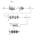
- a billet 1 is heated to a predetermined temperature (generally 1100 to 1300°C) in a heating furnace 2 and then subjected to piercing and rolling by a piercer 3 to produce a hollow shell 4.
- This pierced hollow shell 4 is subjected to drawing and rolling in a mandrel mill 5 to produce a material pipe 4'.
- the pierced hollow shell 4 is subjected to drawing and rolling with a mandrel bar 6 with a lubricant containing carbon such as graphite or the like applied to its surface inserted into the hollow shell 4. Then, the material pipe 4' is re-heated to a predetermined temperature (generally 850 to 1150°C) in a reheating furnace 7 and subjected to finish rolling by a swaging rolling mill 8 such as a stretch reducer or a sizer.
- a predetermined temperature generally 850 to 1150°C
- a material of the material pipe 4' is low carbon steel such as austenitic stainless steel (SUS 304, SUS 316, etc.) or the like
- a material pipe 4' is subjected to drawing and rolling with the mandrel bar 6 with a lubricant containing carbon applied to its surface inserted into the material pipe 4' and re-heated, a carburizing phenomenon, in which a carburized layer having a higher carbon content is formed at an inner surface of the material pipe 4', occurs.
- an amount of the graphite adhering to the surface of the mandrel bar is 100 mg/m 2 or less when a hollow shell is subjected to drawing and rolling by the mandrel mill (for example, refer to Japanese Unexamined Patent Publication No. 2000-24706 ).
- the method of removing the carburized layer or the like by use of an abrasive is unfeasible since the cost of abrasive such as hone is expensive and it takes the time to grind the material pipe.
- the method of removing the lubricant or the like by use of high-pressure water the material pipe is nonuniformly cooled. And, this material pipe may be bent by reheating and may inhibit an operation.
- the present invention was made to solve the problems of the related art, it is an object of the present invention to provide a production method of a seamless pipe and an oxidizing gas supply unit by which carburizing likely produced on an inner surface of a material pipe can be inhibited simply and effectively.
- the present inventors made intensive investigations in order to solve the above-mentioned problems, and consequently found the following matters (A) to (C).
- the present invention has been accomplished with the above-described findings of the inventors. That is, the present invention provides a production method of a seamless pipe or tube comprising the steps of applying a lubricant containing carbon to a mandrel bar, producing a material pipe or tube with a mandrel mill using the mandrel bar to which the lubricant is applied, and reheating the material pipe or tube in a reheating furnace, wherein when a temperature of the material pipe or tube is 550°C or higher and 1000°C or lower in the reheating step, an oxidizing gas is fed into the material pipe or tube.
- the carbon adhering to the inner surface of the material pipe or tube can be burnt even though an amount of the oxidizing gas fed into the material pipe or tube is small, while the diffusion of the carbon from the inner surface of the material pipe or tube to the inside of the material pipe or tube can be inhibited, and therefore carburizing likely produced on an inner surface of the material pipe or tube can be inhibited effectively. Further, since a required amount of the oxidizing gas fed is small, a production cost and a facilities cost of the seamless pipe or tube can be inhibited and carburizing can be readily inhibited.
- a flow rate of the oxidizing gas fed into the material pipe or tube is preferably determined so as to satisfy the condition of the following equation (1): Q ⁇ 7.7394 ⁇ 10 12 ⁇ exp - 22748 ( T ⁇ + P p ) ⁇ 0.5 + 273 ⁇ C in T in + 273 ⁇ 1 ⁇ c ⁇ D c ⁇ A b ⁇ ⁇ ⁇ D p ⁇ L p
- Q represents a flow rate of the oxidizing gas [Nl/sec]
- T ⁇ represents a temperature of atmosphere in the reheating furnace [°C]
- T p represents a temperature of the material pipe or tube at the time when the material pipe or tube is introduced into the reheating furnace [°C]
- C in represents an oxygen content of the oxidizing gas [vol.%]
- T in represents a temperature of the oxidizing gas [°C]
- ⁇ c represents a particle density of carbon which the lubricant applied to the
- a measure of a flow rate Q of the oxidizing gas to be fed can be obtained, and thus the flow rate to be fed can be reduced to the flow rate equal to the right side of the equation (1).
- the present invention provides an oxidizing gas supply unit used in the reheating step in the above-mentioned production method of a seamless pipe or tube.
- the oxidizing gas supply unit is installed in a walking beam reheating furnace in which the material pipe or tube is placed on one of pockets provided on a moving beam and a fixed beam and successively shifted to the other pocket alternately between two kinds of beams to be carried.
- the oxidizing gas supply unit includes nozzles which are respectively disposed at the sides of a plurality of successive pockets provided from the side, which is closest to the material pipe or tube introducing inlet of the fixed beam, toward the material pipe ore tube carrying out side of the fixed beam and each of which ejects an oxidizing gas toward the inside of the material pipe placed on each pocket of the fixed beam.
- the oxidizing gas supply unit of the present invention has a constitution of including nozzles to eject the oxidizing gas at the sides of a plurality of successive pockets provided from the side, which is closest to the material pipe or tube introducing inlet of the fixed beam of a walking beam reheating furnace toward the material pipe or tube carrying out side of the fixed beam.
- the oxidizing gas can be fed into the material pipe or tube almost continuously during a process from immediately after the material pipe or tube is introduced into the reheating furnace to the material pipe or tube is carried through the reheating furnace.
- the oxidizing gas can be fed before a temperature of the material pipe or tube is elevated and becomes equal to the temperature of atmosphere in the reheating furnace (that is, a temperature of the material pipe or tube is higher than 1000°C) and it is possible to satisfy the condition that the oxidizing gas is fed when a temperature of the material pipe is 1000°C or lower.
- a temperature of the material pipe or tube at the time when the material pipe or tube is introduced into the reheating furnace is lower than 550°C
- the ejection of the oxidizing gas from a nozzle, which is provided at a position where a temperature of the material pipe or tube is still lower than 550°C, of a plurality of nozzles successively installed can be stopped, and the oxidizing gas can be ejected from a nozzle at first, which is provided at a position where a temperature of the material pipe or tube can be elevated to 550°C or higher when the material pipe or tube is carried through the reheating furnace, of a plurality of nozzles successively installed.
- the ejection of the oxidizing gas from a nozzle which is provided at a position where a temperature of the material pipe or tube is still lower than 550°C, doesn't have to be stopped as long as the oxidizing gas is ejected from a nozzle, which is provided at a position where a temperature of the material pipe or tube can be elevated to 550°C or higher when the material pipe or tube is carried through the reheating furnace. Therefore, even when a temperature of the material pipe or tube just before being introduced into the reheating furnace is lower than 550°C, it is possible to satisfy the condition of feeding the oxidizing gas when a temperature of the material pipe or tube is 550°C or higher.
- the oxidizing gas supply unit of the present invention when a temperature of the material pipe or tube introduced in the reheating furnace is 550°C or higher and 1000°C or lower, the oxidizing gas can be fed into the material pipe or tube.
- Fig. 3 are schematic views showing schematic constitutions of a reheating furnace and an oxidizing gas supply unit installed at the reheating furnace, to which a production method of a seamless pipe of an embodiment of the present invention is applied.
- Fig. 3A is a front sectional view and Fig. 3B is a side sectional view.
- a reheating furnace 10 of the present embodiment is a so-called walking beam reheating furnace.
- the material pipe P subjected to drawing and rolling in a mandrel mill is introduced into the reheating furnace 10 through an inlet 11, and placed on one of pockets 14 provided on a moving beam 12 and a fixed beam 13 and successively shifted to the other pocket alternately between two kinds of beams to be carried in a direction of an arrow of Fig. 3A .
- the oxidizing gas supply unit (hereinafter, appropriately referred to as a "gas supply unit") 20 is installed in the reheating furnace 10.
- the gas supply unit 20 includes nozzles 21 which are respectively disposed at the sides of a plurality (6 in the present embodiment) of successive pockets 14 provided from the side of the fixed beam 13 closest to the inlet 11 toward the material pipe carrying out side of the fixed beam 13, and each of which ejects an oxidizing gas (air in the present embodiment) A toward the inside of the material pipe P placed on the foregoing each pocket 14 of the fixed beam 13. More specifically, each nozzle 21 is inserted into a side wall 15 of the reheating furnace 10 positioned at the sides of the above-mentioned successive pockets 14 of the fixed beam 13. And, each nozzle 21 is constructed so as to eject the air A having flown in from a base portion through a nozzle tip toward the inside of the material pipe P.
- the air A is fed into the material pipe P by use of the gas supply unit 20 when a temperature of the material pipe P introduced in the reheating furnace 10 is 550°C or higher and 1000°C or lower. More specifically, the gas supply unit 20 is constructed so as to eject the air A from each nozzle 21 of the gas supply unit 20 if temperatures of the material pipes P introduced into the reheating furnace 10 are 550°C or higher and 1000°C or lower in a state of being placed on the foregoing respective pockets 14 (six successive pockets 14 provided from the side closest to the inlet 11 toward the material pipe carrying out side) of the fixed beam 13.
- a temperature of the material pipe P placed on the foregoing each pocket 14 an actually-measured temperature previously measured by use of a thermocouple or the like for various parameters such as a temperature of atmosphere in the reheating furnace 10, a temperature of the material pipe P at the time when the material pipe is introduced into the reheating furnace 10, and a dimension of the material pipe P may be used.
- a temperature of the material pipe P can be calculated by use of a heat transfer calculation model. Then, it may be determined whether or not the actually-measured temperature or calculated temperature is 550°C or higher and 1000°C or lower.
- the air is fed into the material pipe P when a temperature of the material pipe P introduced in the reheating furnace 10 is 550°C or higher and 1000°C or lower, as described above with reference to Fig. 2 , the carbon adhering to the inner surface of the material pipe P can be burnt even though an amount of air is small, while the diffusion of the carbon from the inner surface of the material pipe to the inside of the material pipe can be inhibited. Therefore, carburizing likely produced on an inner surface of the material pipe P can be inhibited effectively. Further, since a required amount of the air fed is small, a production cost and a facilities cost of the seamless pipe can be inhibited and carburizing can be readily inhibited.
- test furnace a heating furnace for a test
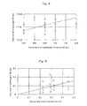
- Fig. 4 is a graph showing the results of the above test 1. Points denoted by a "o” in Fig. 4 represent data in which the carburizing did not occur (a ratio of carbon concentration increment on the inner surface of the material pipe to the set carbon concentration of the material pipe was 0.010% or less), and points denoted by a " ⁇ " represent data in which the carburizing occurred (a ratio of carbon concentration increment on the inner surface of the material pipe to the set carbon concentration of the material pipe was more than 0.010%). As shown in Fig.
- test 1 The same test as in test 1 was performed except for maintaining the temperature of the material pipe at the time when the material pipe was introduced into the test furnace at constant temperature of 650°C and performing a test repeatedly for a plurality of material pipes having different dimensions.
- Fig. 5 is a graph showing the results of the above test 2. Points denoted by a " ⁇ " or a " ⁇ " in Fig. 5 represent the same as Fig. 4 . As shown in Fig. 5 , it is found that when the dimension of the material pipe (the inner surface area) is enlarged, the flow rate of the oxidizing gas required for preventing the carburized layer from being produced have to be increased (a required flow rate of the oxidizing gas is almost proportional to the inner surface area).
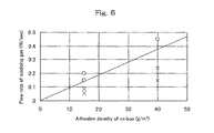
- test 1 The same test as in test 1 was performed except for maintaining the temperature of the material pipe at the time when the material pipe was introduced into the test furnace at constant temperature of 650°C and performing a test repeatedly for a plurality of material pipes having different adhesion densities of carbon applied to the mandrel bar in drawing and rolling.
- Fig. 6 is a graph showing the results of the above test 3. Points denoted by a " ⁇ " or a " ⁇ " in Fig. 6 represent the same as Fig. 4 . As shown in Fig. 6 , it is found that when the adhesion densities of carbon applied to the mandrel bar in drawing and rolling is increased, the flow rate of the oxidizing gas required for preventing the carburized layer from being produced have to be increased (a required flow rate of the oxidizing gas is almost proportional to the adhesion densities of carbon).
- the present inventors derived a calculation equation for determining a flow rate (minimum flow rate) of the oxidizing gas to be based on the test results of the above tests 1 to 3 using the test furnace and the various test results at the reheating furnace 10 installed on a production line of the seamless pipe.
- a flow rate of the oxidizing gas fed into the material pipe or tube P is determined so as to satisfy the condition of the following equation (1): Q ⁇ 7.7394 ⁇ 10 12 ⁇ exp - 22748 ( T ⁇ + P p ) ⁇ 0.5 + 273 ⁇ C in T in + 273 ⁇ 1 ⁇ c ⁇ D c ⁇ A b ⁇ ⁇ ⁇ D p ⁇ L p
- Q represents a flow rate of the oxidizing gas [Nl/sec]
- T ⁇ represents a temperature of atmosphere in the reheating furnace [°C]
- T p represents a temperature of the material pipe or tube at the time when the material pipe or tube is introduced into the reheating furnace [°C]
- C in represents an oxygen content of the oxidizing gas [vol.%]
- T in represents a temperature of the oxidizing gas [°C]
- ⁇ c represents a particle density of carbon which the lubricant applied to the mand
- Table 1 shows an example of the feeding conditions of the oxidizing gas (air) at the reheating furnace 10 shown in Fig. 3 and the results of evaluating the presence or absence of the carburizing on the inner surface of the material pipe carried out from the reheating furnace at various conditions.
- numeric values shown in a box of "C adhering to bar” indicated in Table 1 represent an adhesion density A b or carbon which the lubricant applied to the mandrel bar contains
- numeric values shown in a box of "Temperature of material pipe introduced” represent a temperature T p of the material pipe at the time when the material pipe is introduced into the reheating furnace
- numeric values shown in a box of "Flow rate of gas” represent a flow rate Q of the oxidizing gas (air) fed into the material pipe P.
- the meanings or " ⁇ ” and “ ⁇ ” shown in a box of "Carburizing evaluation” are the same as in Figs. 4 to 6 .
- a in a box of "Size” in Table 1 represents; an inner diameter D p of the material pipe is 0.143 m and a length L p is 30 m.
- B in a box of "Size” in Table 1 represents; an inner diameter D p of the material pipe is 0.092 m, and a length L p is 20 m.
- a temperature T ⁇ of atmosphere in the reheating furnace 10 is set at 1000°C
- an oxygen content C in of the oxidizing gas is set at 20vol.%
- a temperature T in of the oxidizing gas is set at 25°C
- a particle density ⁇ c of carbon which the lubricant applied to the mandrel bar contains is set at 1000 kg/m 3
- a particle diameter D c of carbon which the lubricant applied to the mandrel bar contains is set at 25 ⁇ m.
Landscapes
- Chemical & Material Sciences (AREA)
- Engineering & Computer Science (AREA)
- Mechanical Engineering (AREA)
- Physics & Mathematics (AREA)
- Thermal Sciences (AREA)
- Crystallography & Structural Chemistry (AREA)
- Materials Engineering (AREA)
- Metallurgy (AREA)
- Organic Chemistry (AREA)
- Manufacturing & Machinery (AREA)
- Heat Treatment Of Articles (AREA)
- Solid-Phase Diffusion Into Metallic Material Surfaces (AREA)
Applications Claiming Priority (2)
| Application Number | Priority Date | Filing Date | Title |
|---|---|---|---|
| JP2006096888A JP4688037B2 (ja) | 2006-03-31 | 2006-03-31 | 継目無鋼管の製造方法及び酸化性ガス供給装置 |
| PCT/JP2007/055615 WO2007114041A1 (ja) | 2006-03-31 | 2007-03-20 | 継目無管の製造方法及び酸化性ガス供給装置 |
Publications (4)
| Publication Number | Publication Date |
|---|---|
| EP2002903A2 true EP2002903A2 (de) | 2008-12-17 |
| EP2002903A9 EP2002903A9 (de) | 2009-04-22 |
| EP2002903A4 EP2002903A4 (de) | 2012-07-04 |
| EP2002903B1 EP2002903B1 (de) | 2013-06-19 |
Family
ID=38563310
Family Applications (1)
| Application Number | Title | Priority Date | Filing Date |
|---|---|---|---|
| EP07739058.1A Ceased EP2002903B1 (de) | 2006-03-31 | 2007-03-20 | Verfahren zur herstellung eines nahtlosen rohrs, insbesondere unter benutzung eines geräts zur versorgung mit einem oxidierenden gas |
Country Status (5)
| Country | Link |
|---|---|
| US (1) | US8464568B2 (de) |
| EP (1) | EP2002903B1 (de) |
| JP (1) | JP4688037B2 (de) |
| CN (1) | CN101448585B (de) |
| WO (1) | WO2007114041A1 (de) |
Cited By (1)
| Publication number | Priority date | Publication date | Assignee | Title |
|---|---|---|---|---|
| US8863564B2 (en) * | 2006-04-24 | 2014-10-21 | Sumitomo Metal Industries, Ltd. | Lubricant composition for hot metal working and method of hot metal working using the same |
Family Cites Families (16)
| Publication number | Priority date | Publication date | Assignee | Title |
|---|---|---|---|---|
| JPH0734926B2 (ja) | 1990-08-31 | 1995-04-19 | 川崎製鉄株式会社 | オーステナイト系ステンレス継目無鋼管の製造方法 |
| JP2924523B2 (ja) * | 1992-12-11 | 1999-07-26 | 住友金属工業株式会社 | マンドレルミルによる金属管の延伸圧延方法 |
| JPH06182427A (ja) | 1992-12-21 | 1994-07-05 | Kawasaki Steel Corp | 継目無鋼管の浸炭防止方法 |
| EP0698426A1 (de) * | 1994-08-18 | 1996-02-28 | MANNESMANN Aktiengesellschaft | Walzdornwechselvorrichtung für Stopfenwalzwerke |
| JPH0857505A (ja) * | 1994-08-19 | 1996-03-05 | Sumitomo Metal Ind Ltd | オーステナイト系ステンレス鋼管の製造方法 |
| JP3369320B2 (ja) | 1994-09-19 | 2003-01-20 | 三菱マテリアル株式会社 | 傾斜圧延装置 |
| JPH0890043A (ja) | 1994-09-26 | 1996-04-09 | Sumitomo Metal Ind Ltd | ステンレス継目無鋼管の製造方法 |
| JP2867910B2 (ja) | 1995-02-23 | 1999-03-10 | 住友金属工業株式会社 | 継目無鋼管の浸炭防止方法 |
| US5699690A (en) * | 1995-06-19 | 1997-12-23 | Sumitomo Metal Industries, Ltd. | Method and apparatus for manufacturing hollow steel bars |
| JP3855300B2 (ja) * | 1996-04-19 | 2006-12-06 | 住友金属工業株式会社 | 継目無鋼管の製造方法および製造設備 |
| JP3307294B2 (ja) * | 1997-09-26 | 2002-07-24 | 住友金属工業株式会社 | 表面性状に優れた継目無鋼管の製造方法および継目無鋼管の製造設備 |
| JP2000024706A (ja) | 1998-07-14 | 2000-01-25 | Sumitomo Metal Ind Ltd | 継目無鋼管の製造方法および耐食性に優れた継目無合金鋼鋼管 |
| JP2001105007A (ja) | 1999-10-08 | 2001-04-17 | Sumitomo Metal Ind Ltd | マンドレルミル圧延方法 |
| JP4111907B2 (ja) | 2003-12-08 | 2008-07-02 | エス・バイ・エル株式会社 | 部材取付構造 |
| TWI265053B (en) * | 2004-01-16 | 2006-11-01 | Sumitomo Metal Ind | Method for producing seamless pipe |
| WO2007126005A1 (ja) * | 2006-04-28 | 2007-11-08 | Sumitomo Metal Industries, Ltd. | ステンレス鋼管の製造方法 |
-
2006
- 2006-03-31 JP JP2006096888A patent/JP4688037B2/ja not_active Expired - Lifetime
-
2007
- 2007-03-20 WO PCT/JP2007/055615 patent/WO2007114041A1/ja not_active Ceased
- 2007-03-20 US US12/225,726 patent/US8464568B2/en active Active
- 2007-03-20 CN CN200780018203.1A patent/CN101448585B/zh not_active Expired - Fee Related
- 2007-03-20 EP EP07739058.1A patent/EP2002903B1/de not_active Ceased
Cited By (1)
| Publication number | Priority date | Publication date | Assignee | Title |
|---|---|---|---|---|
| US8863564B2 (en) * | 2006-04-24 | 2014-10-21 | Sumitomo Metal Industries, Ltd. | Lubricant composition for hot metal working and method of hot metal working using the same |
Also Published As
| Publication number | Publication date |
|---|---|
| JP4688037B2 (ja) | 2011-05-25 |
| US20110239720A1 (en) | 2011-10-06 |
| EP2002903A9 (de) | 2009-04-22 |
| CN101448585B (zh) | 2011-07-27 |
| US8464568B2 (en) | 2013-06-18 |
| EP2002903A4 (de) | 2012-07-04 |
| EP2002903B1 (de) | 2013-06-19 |
| CN101448585A (zh) | 2009-06-03 |
| JP2007268562A (ja) | 2007-10-18 |
| WO2007114041A1 (ja) | 2007-10-11 |
Similar Documents
| Publication | Publication Date | Title |
|---|---|---|
| JP4853515B2 (ja) | ステンレス鋼管の製造方法 | |
| EP1001859B1 (de) | Verfahren zur herstellung von wälzlagerringen aus stahl | |
| EP0743106A1 (de) | Verfahren zur Herstellung eines nahtlosen Rohres | |
| EP2422892A1 (de) | Verfahren zur herstellung eines nahtlosen rohrs und vorrichtung zur durchführung des verfahrens | |
| DE10143073B4 (de) | Stahl mit niedrigem Kohlenstoffgehalt und Verfahren zum Herstellen eines strukturellen Stahlrohrs mit hoher Zähigkeit bei kalten Temperaturen | |
| EP2025421B1 (de) | Verfahren zur herstellung eines nahtlosen rohrs aus rostfreiem stahl | |
| EP2002903B1 (de) | Verfahren zur herstellung eines nahtlosen rohrs, insbesondere unter benutzung eines geräts zur versorgung mit einem oxidierenden gas | |
| JPH09271811A (ja) | 二相ステンレス鋼製継目無鋼管の製造方法 | |
| CN120243676A (zh) | 一种基于mpm机组的纯钛及钛合金无缝管轧制方法 | |
| JP2000351015A (ja) | 金属管の引き抜き加工方法 | |
| JPH0890043A (ja) | ステンレス継目無鋼管の製造方法 | |
| JP2586274B2 (ja) | クロム含有鉄基合金の継目無鋼管の製造方法 | |
| JPH0857505A (ja) | オーステナイト系ステンレス鋼管の製造方法 | |
| JP2001162305A (ja) | 鋼管の製造方法 | |
| EP3639938A1 (de) | Herstellungsverfahren für ein nahtloses metallrohr | |
| JP3232857B2 (ja) | ステンレス継目無鋼管の製造方法 | |
| JP2001105007A (ja) | マンドレルミル圧延方法 | |
| JPH1015604A (ja) | 高合金継目無鋼管の管圧延方法 | |
| JPH04294803A (ja) | マンドレルミルの圧延方法 | |
| JP2002316207A (ja) | 熱間圧延による条鋼材の製造方法 | |
| CN113088662A (zh) | 一种轴承钢管无氧球化退火工艺中dx气体碳势控制方法 | |
| Gorbanev | Complex of investigations performed during mastering, operation, and improvement of design of high-speed wire blocks. | |
| JPH105821A (ja) | 継目無鋼管製造用プラグの熱処理方法および継目無鋼管の製造方法 | |
| JPH07136703A (ja) | シームレスパイプ圧延方法 | |
| JPH05185113A (ja) | 圧延クラッド継目無管の製造方法 |
Legal Events
| Date | Code | Title | Description |
|---|---|---|---|
| PUAI | Public reference made under article 153(3) epc to a published international application that has entered the european phase |
Free format text: ORIGINAL CODE: 0009012 |
|
| 17P | Request for examination filed |
Effective date: 20080923 |
|
| AK | Designated contracting states |
Kind code of ref document: A2 Designated state(s): DE FR IT |
|
| PUAB | Information related to the publication of an a document modified or deleted |
Free format text: ORIGINAL CODE: 0009199EPPU |
|
| DAX | Request for extension of the european patent (deleted) | ||
| RBV | Designated contracting states (corrected) |
Designated state(s): DE FR IT |
|
| A4 | Supplementary search report drawn up and despatched |
Effective date: 20120604 |
|
| RIC1 | Information provided on ipc code assigned before grant |
Ipc: C21D 1/74 20060101ALI20120529BHEP Ipc: B21B 17/02 20060101AFI20120529BHEP Ipc: C21D 9/08 20060101ALI20120529BHEP Ipc: B21B 23/00 20060101ALI20120529BHEP Ipc: C21D 3/04 20060101ALI20120529BHEP Ipc: C21D 1/70 20060101ALI20120529BHEP Ipc: B21B 25/04 20060101ALI20120529BHEP Ipc: B21B 45/00 20060101ALI20120529BHEP |
|
| GRAP | Despatch of communication of intention to grant a patent |
Free format text: ORIGINAL CODE: EPIDOSNIGR1 |
|
| RAP1 | Party data changed (applicant data changed or rights of an application transferred) |
Owner name: NIPPON STEEL & SUMITOMO METAL CORPORATION |
|
| GRAS | Grant fee paid |
Free format text: ORIGINAL CODE: EPIDOSNIGR3 |
|
| GRAA | (expected) grant |
Free format text: ORIGINAL CODE: 0009210 |
|
| AK | Designated contracting states |
Kind code of ref document: B1 Designated state(s): DE FR IT |
|
| REG | Reference to a national code |
Ref country code: DE Ref legal event code: R096 Ref document number: 602007031129 Country of ref document: DE Effective date: 20130814 |
|
| PLBE | No opposition filed within time limit |
Free format text: ORIGINAL CODE: 0009261 |
|
| STAA | Information on the status of an ep patent application or granted ep patent |
Free format text: STATUS: NO OPPOSITION FILED WITHIN TIME LIMIT |
|
| 26N | No opposition filed |
Effective date: 20140320 |
|
| REG | Reference to a national code |
Ref country code: DE Ref legal event code: R097 Ref document number: 602007031129 Country of ref document: DE Effective date: 20140320 |
|
| REG | Reference to a national code |
Ref country code: FR Ref legal event code: PLFP Year of fee payment: 9 |
|
| REG | Reference to a national code |
Ref country code: FR Ref legal event code: PLFP Year of fee payment: 10 |
|
| REG | Reference to a national code |
Ref country code: FR Ref legal event code: PLFP Year of fee payment: 11 |
|
| REG | Reference to a national code |
Ref country code: FR Ref legal event code: PLFP Year of fee payment: 12 |
|
| REG | Reference to a national code |
Ref country code: DE Ref legal event code: R082 Ref document number: 602007031129 Country of ref document: DE Representative=s name: DOMPATENT VON KREISLER SELTING WERNER - PARTNE, DE Ref country code: DE Ref legal event code: R081 Ref document number: 602007031129 Country of ref document: DE Owner name: NIPPON STEEL CORPORATION, JP Free format text: FORMER OWNER: NIPPON STEEL & SUMITOMO METAL CORPORATION, TOKYO, JP |
|
| PGFP | Annual fee paid to national office [announced via postgrant information from national office to epo] |
Ref country code: DE Payment date: 20220203 Year of fee payment: 16 |
|
| PGFP | Annual fee paid to national office [announced via postgrant information from national office to epo] |
Ref country code: IT Payment date: 20220210 Year of fee payment: 16 Ref country code: FR Payment date: 20220209 Year of fee payment: 16 |
|
| REG | Reference to a national code |
Ref country code: DE Ref legal event code: R119 Ref document number: 602007031129 Country of ref document: DE |
|
| PG25 | Lapsed in a contracting state [announced via postgrant information from national office to epo] |
Ref country code: FR Free format text: LAPSE BECAUSE OF NON-PAYMENT OF DUE FEES Effective date: 20230331 Ref country code: DE Free format text: LAPSE BECAUSE OF NON-PAYMENT OF DUE FEES Effective date: 20231003 |
|
| PG25 | Lapsed in a contracting state [announced via postgrant information from national office to epo] |
Ref country code: IT Free format text: LAPSE BECAUSE OF NON-PAYMENT OF DUE FEES Effective date: 20230320 |