EP2002913A1 - Umlenkvorrichtung einer Seilsägevorrichtung - Google Patents
Umlenkvorrichtung einer Seilsägevorrichtung Download PDFInfo
- Publication number
- EP2002913A1 EP2002913A1 EP20080103974 EP08103974A EP2002913A1 EP 2002913 A1 EP2002913 A1 EP 2002913A1 EP 20080103974 EP20080103974 EP 20080103974 EP 08103974 A EP08103974 A EP 08103974A EP 2002913 A1 EP2002913 A1 EP 2002913A1
- Authority
- EP
- European Patent Office
- Prior art keywords
- cover
- roller
- protective cover
- deflection
- guide
- Prior art date
- Legal status (The legal status is an assumption and is not a legal conclusion. Google has not performed a legal analysis and makes no representation as to the accuracy of the status listed.)
- Granted
Links
Images

Classifications
-
- B—PERFORMING OPERATIONS; TRANSPORTING
- B23—MACHINE TOOLS; METAL-WORKING NOT OTHERWISE PROVIDED FOR
- B23D—PLANING; SLOTTING; SHEARING; BROACHING; SAWING; FILING; SCRAPING; LIKE OPERATIONS FOR WORKING METAL BY REMOVING MATERIAL, NOT OTHERWISE PROVIDED FOR
- B23D57/00—Sawing machines or sawing devices not covered by one of the preceding groups B23D45/00 - B23D55/00
- B23D57/003—Sawing machines or sawing devices working with saw wires, characterised only by constructional features of particular parts
-
- Y—GENERAL TAGGING OF NEW TECHNOLOGICAL DEVELOPMENTS; GENERAL TAGGING OF CROSS-SECTIONAL TECHNOLOGIES SPANNING OVER SEVERAL SECTIONS OF THE IPC; TECHNICAL SUBJECTS COVERED BY FORMER USPC CROSS-REFERENCE ART COLLECTIONS [XRACs] AND DIGESTS
- Y10—TECHNICAL SUBJECTS COVERED BY FORMER USPC
- Y10T—TECHNICAL SUBJECTS COVERED BY FORMER US CLASSIFICATION
- Y10T83/00—Cutting
- Y10T83/869—Means to drive or to guide tool
- Y10T83/872—With guard means
Definitions
- the invention relates to a deflection device of a Seailsägevorraum with a deflection roller having a deflection roller at least partially surrounding, stationary protective cover and at least one cover, which is displaceable along a spaced apart radially to the roller axis of the deflection roller track.
- Wire saw devices are used in particular for sawing large workpieces, such. B. stone blocks, wherein the sawing wire cutting body, such as sintered diamond beads, and is driven by a motor assembly of Seilsägevorraum.
- the sawing wire cutting body such as sintered diamond beads
- the sawing wire is guided around the workpiece to be cut and aligned with this. Due to the nature of the stress on the sawing cable, a rope break can suddenly occur and the torn sawing rope can whip through the air like a whip.
- a deflection device of a sawing device with a deflection roller which has a deflection roller at least partially surrounding, stationary protective cover and a cover with a radial wall portion as protection against a cracked saw chain.
- the protective cover and the cover have mutually engageable through openings for carrying out a fastening means, whereby the cover is displaceable along a spaced radially to the roller axis of the guide roller track.
- the cover can therefore be set in a predetermined grid depending on the orientation of the saw chain to be deflected on the stationary protective cover.
- a disadvantage of the known solution is that the cover can be arranged only in a predetermined grid with respect to the protective cover and the determination of the cover is complex, since the cover must be removed at each positioning.
- the object of the invention is to provide a deflection device of a wire saw device, which ensures protection against the sawing cable in a rope break and is easily adjustable.
- the cover is pivotally mounted on the protective cover.
- the at least one cover element can be easily aligned by pivoting about the pivot axis relative to the course of the sawing cable or the cable deflection angle in a large angular range to the stationary protective cover. If, for example, a rope break occurs during the sawing process, then the cover element restricts the whip of the broken sawing cable through the enlarged covered area around the deflection roller.
- the cover prevents, especially when this has a radially spaced wall portion that the sawing wire adhering dirt and water is thrown in the deflection of the sawing cable to the outside.
- the protective cover also has a radially spaced with respect to the roller axis of the guide roller wall portion, so that these wall portions cover each other in a partially overlapping arrangement to a large area around the guide pulley radially outward.
- the radial distance of the corresponding wall portion of the cover is greater than the largest radial extent of the stationary protective cover in each case based on the roller axis of the guide roller, so that the cover over the protective cover is pivoted away.
- the cover is pivotally mounted on the roller axis of the guide roller, which allows a simple arrangement of the cover with a few individual parts.
- the at least one cover element is arranged or fixed pivotably on the protective cover via a link connection.
- the link connection includes, for example, a slot and a cooperating with the slot guide pin, wherein the slot z. B. is arranged in the cover and the guide pin on the protective cover.
- the slot can also be arranged in the protective cover, wherein the cooperating with this guide pin is arranged on the pivotable cover.
- a fixing device for fixing the cover is provided in the desired orientation with respect to the protective cover so that the orientation of the cover to the stationary protective cover can not change unintentionally.
- the fixing device exerts a clamping force on the cover element and the protective cover in the clamped state, wherein the deflection roller can continue to rotate freely about the roller axis.
- the fixing device comprises a spring element, which is designed for example as a plate spring and at least on the cover, z. B. acts frictionally.
- the fixing device is provided in the region of the roller axis of the deflection roller, which allows a simple fixation with few components.
- a guide device for the cover is provided for guiding the cover to the protective cover.
- the guide device advantageously has two stops for limiting the pivoting range, between which the cover element can be fixed in any angular position between the stops to the protective cover.
- the or a further fixing device for the cover is part of the guide means, wherein advantageously a suitable fixing element simultaneously forms the stop element of the guide means.
- the guide device preferably comprises a slot and a stop element arranged in the slot, wherein the ends of the slot with the stop element determine the maximum pivoting range of the cover. Come the ends of the slot with the stop element into abutment further pivoting of the cover is prevented.
- the slot in the cover and the stop element are provided on the protective cover.
- the slot has a constant width and extends along a curved, radially to the roller axis of the guide roller extending longitudinal axis, so that between the stop element and the slot over the entire pivoting range of the cover the intended game changed only slightly.
- the stop element is, for example, facing away from the protective cover of the deflection roller, projecting element, such as a bolt or a cam.
- the free, the sawing wire end facing a radially spaced from the roller axis of the guide roller wall portion of the cover is rounded, so that in this area no sharp edge of the free end is present. This will in the case a cable break the less damaged with the free end of the cover into abutting saw wire.
- a deflection device 11 of a Seailsägevorraum with two pulleys 12 is shown, which are fixed to a support member 6. Both deflection rollers 12 are formed substantially the same and each have a respective deflecting roller 12 partially surrounding, stationary protective cover 13.
- the protective cover 13 has regions in cross-section transverse to the deflection roller 12 a U-shaped cross-section with a relative to the roller axis 15 of the guide roller 12 radial wall portion 18.
- a passage opening for the storage of the roller axis 15 of the guide roller 12 is provided.
- the protective cover 13 is releasably fixed to the support member 6.
- a cover member 23 is provided with a radially in relation to the roller axis 15 of the guide roller 12 radially spaced wall portion 25 which is pivotally mounted on the protective cover 13.
- the cover member 23 is pivotally mounted on the roller axle 15 of the guide roller 12.
- the cover member 23 has in cross section to the guide roller 12 also has a U-shaped configuration and in the region of the free ends of the legs 24 of the cover 23 each have a passage opening for the roller shaft 15 of the guide roller 12.
- the radial distance of the radially spaced wall portion 25 of the cover 23 is greater than the radial distance of the radial wall portion 18 of the protective cover 13 is formed in each case based on the roller axis 15 of the guide roller 12th
- a guide device 31 is provided in each case, which arranged in the leg 24 of the cover 23, at a certain distance from the roller axis 15 of the guide roller 12 arcuately extending slot 32 and one of the Leg 14 of the protective cover 13 protruding and arranged in the slot 32 stop member 33 includes.
- a fixing device 41 for fixing the cover 23 in the desired orientation to the protective cover 13 is provided on the roller shaft 15 of the guide roller 12.
- the fixing device 41 comprises as a spring element 43, a plate spring, which is arranged between a screwed onto the roller shaft 15 of the guide roller 12 fixing nut 42 and the outside of the cover 23.
- the spring element 43 frictionally acts on the cover 23 and fixes this in the desired orientation.
- the fixing device 41 is designed such that the deflection roller 12 can rotate freely even in its tensioned state.
- Each cover element 23 has at the free, the sawing wire 7 facing the end 26 of the radially to the roller axis 15 of the guide roller 13 spaced wall portion 25 a rounding 27.
- a Seilsägevorraum has a guide roller 52, which is partially surrounded by a stationary protective cover 53 and a pivotally mounted on the protective cover 53 cover 63.
- the cover member 63 has in cross section to the guide roller 52 also has a U-shaped configuration and in the legs 64 a a backdrop forming, bent extending slot 72, which with a fixing means 73, z. B. in the form of a arranged on the stationary protective cover 53 screw, a link connection forms.
- the link connection allows a simple pivoting of the cover 63 relative to the stationary protective cover 53 or on the roller shaft 55 of the guide roller 52 and at the same time forms the fixing device 81 for the cover 63 from.
- a Seailsägevorraum has a guide roller 92, which is partially surrounded by a stationary protective cover 93 and two pivotally mounted on the protective cover 93 cover members 102 and 103.
- the radial distance of the radially spaced wall portion 105 of the cover 103 is greater than the radial Distance of the radially spaced wall portion 108 of the cover 102 is formed, wherein the radial distance of the radially spaced wall portion 108 of the cover 102 is greater than the radial distance of the radial wall portion 98 of the protective cover 93 is formed, each based on the roller axis 95 of the guide roller 92.
- the cover 102 and 103 are fan-foldable and expandable.
Landscapes
- Engineering & Computer Science (AREA)
- Mechanical Engineering (AREA)
- Processing Of Stones Or Stones Resemblance Materials (AREA)
- Sawing (AREA)
- Pulleys (AREA)
- Finish Polishing, Edge Sharpening, And Grinding By Specific Grinding Devices (AREA)
- Flexible Shafts (AREA)
Abstract
Description
- Die Erfindung betrifft eine Umlenkvorrichtung einer Seilsägevorrichtung mit einer Umlenkrolle, die eine die Umlenkrolle zumindest bereichsweise umgebende, ortsfeste Schutzabdeckung sowie zumindest ein Abdeckelement aufweist, das entlang einer radial zur Rollenachse der Umlenkrolle beabstandeten Bahn versetzbar ist.
- Seilsägevorrichtungen dienen insbesondere dem Sägen von grossen Werkstücken, wie z. B. von Steinblöcken, wobei das Sägeseil Schneidkörper, wie beispielsweise gesinterte Diamantperlen, aufweist und von einer Motoranordnung der Seilsägevorrichtung angetrieben wird. Mittels Umlenkvorrichtungen mit Umlenkrollen wird das Sägeseil um das zu schneidende Werkstück geführt und zu diesem ausgerichtet. Aufgrund der Art der Beanspruchung des Sägeseils kann plötzlich ein Seilriss auftreten und das gerissene Sägeseil peitschenartig durch die Luft schnellen.
- Aus der
EP 1 528 852 B1 ist eine Umlenkvorrichtung einer Sägevorrichtung mit einer Umlenkrolle bekannt, die als Schutz vor einer gerissenen Sägekette eine die Umlenkrolle zumindest bereichsweise umgebende, ortsfeste Schutzabdeckung sowie ein Abdeckelement mit einem radialen Wandabschnitt aufweist. Die Schutzabdeckung und das Abdeckelement weisen miteinander in Übereinstimmung bringbare Durchführöffnungen zur Durchführung eines Befestigungsmittels auf, womit das Abdeckelement entlang einer radial zur Rollenachse der Umlenkrolle beabstandeten Bahn versetzbar ist. Das Abdeckelement kann also in einem vorbestimmten Raster je nach Ausrichtung der umzulenkenden Sägekette an der ortsfesten Schutzabdeckung festgelegt werden. - Nachteilig an der bekannten Lösung ist, dass das Abdeckelement nur in einem vorbestimmten Raster in Bezug auf die Schutzabdeckung angeordnet werden kann und die Festlegung des Abdeckelementes aufwändig ist, da das Abdeckelement bei jeder Positionierung abgenommen werden muss.
- Aufgabe der Erfindung ist es, eine Umlenkvorrichtung einer Seilsägevorrichtung zu schaffen, die einen Schutz vor dem Sägeseil bei einem Seilriss gewährleistet und dabei einfach einstellbar ist.
- Die Aufgabe ist durch die Merkmale des unabhängigen Anspruchs gelöst. Vorteilhafte Weiterbildungen sind in den Unteransprüchen dargelegt.
- Gemäss der Erfindung ist das Abdeckelement verschwenkbar an der Schutzabdeckung angeordnet.
- Das zumindest eine Abdeckelement kann einfach durch Verschwenken um die Schwenkachse bezogen auf den Verlauf des Sägeseils beziehungsweise den Seil-Umlenkwinkel in einem grossen Winkelbereich zur ortsfesten Schutzabdeckung ausgerichtet werden. Tritt beispielsweise beim Sägevorgang ein Seilriss auf, so schränkt das Abdeckelement das Peitschen des gerissenen Sägeseils durch den vergrösserten abgedeckten Bereich um die Umlenkrolle ein.
- Zudem verhindert das Abdeckelement, insbesondere wenn dieses einen radial beabstandeten Wandabschnitt aufweist, dass dem Sägeseil anhaftender Schmutz und Wasser bei der Umlenkung des Sägeseils nach aussen hin weggeschleudert wird. Vorteilhaft weist die Schutzabdeckung ebenfalls einen in Bezug auf die Rollenachse der Umlenkrolle radial beabstandeten Wandabschnitt auf, so dass diese Wandabschnitte in einer teilweise überlappenden Anordnung zueinander einen grossen Bereich um die Umlenkrolle nach radial aussen abdecken. Weiter vorteilhaft ist der radiale Abstand des entsprechenden Wandabschnitts des Abdeckelementes grösser als die grösste radiale Erstreckung der ortsfesten Schutzabdeckung jeweils bezogen auf die Rollenachse der Umlenkrolle, damit das Abdeckelement über die Schutzabdeckung hinweg verschwenkbar ist.
- Bevorzugt ist das Abdeckelement schwenkbar an der Rollenachse der Umlenkrolle gelagert, was eine einfache Anordnung des Abdeckelementes mit wenigen einzelnen Teilen ermöglicht.
- Alternativ ist das zumindest eine Abdeckelement über eine Kulissenverbindung verschwenkbar an der Schutzabdeckung angeordnet beziehungsweise festgelegt. Die Kulissenverbindung umfasst beispielsweise eine Langloch und einen mit dem Langloch zusammenwirkenden Führungsstift, wobei das Langloch z. B. in dem Abdeckelement und der Führungsstift an der Schutzabdeckung angeordnet ist. Das Langloch kann auch in der Schutzabdeckung angeordnet sein, wobei der mit diesem zusammenwirkende Führungsstift an dem verschwenkbaren Abdeckelement angeordnet ist.
- Vorzugsweise ist eine Fixiervorrichtung zur Festlegung des Abdeckelementes in der gewünschten Ausrichtung in Bezug auf die Schutzabdeckung vorgesehen, damit sich die Ausrichtung des Abdeckelementes zur ortsfesten Schutzabdeckung nicht ungewollt verändern kann. Vorteilhaft übt die Fixiervorrichtung im verspannten Zustand eine Klemmkraft auf das Abdeckelement und die Schutzabdeckung aus, wobei die Umlenkrolle weiterhin um die Rollenachse frei drehen kann.
- In einer bevorzugten Ausführung umfasst die Fixiervorrichtung ein Federelement, das beispielsweise als Tellerfeder ausgebildet ist und zumindest auf das Abdeckelement, z. B. reibschlüssig wirkt. Vorteilhaft ist die Fixiervorrichtung im Bereich der Rollenachse der Umlenkrolle vorgesehen, was eine einfache Fixierung mit wenigen Bestandteilen ermöglicht.
- Vorzugsweise ist zur Führung des Abdeckelementes zu der Schutzabdeckung eine Führungsvorrichtung für das Abdeckelement vorgesehen. Die Führungsvorrichtung weist zur Begrenzung des Verschwenkbereichs vorteilhaft zwei Anschläge auf, zwischen denen das Abdeckelement in einer beliebigen Winkelstellung zwischen den Anschlägen zu der Schutzabdeckung festlegbar ist. In einer Variante ist die oder eine weitere Fixiervorrichtung für das Abdeckelement Bestandteil der Führungseinrichtung, wobei vorteilhaft ein dazu geeignetes Fixierelement gleichzeitig das Anschlagelement der Führungseinrichtung ausbildet.
- Bevorzugt umfasst die Führungseinrichtung ein Langloch sowie ein im Langloch angeordnetes Anschlagelement, wobei die Enden des Langlochs mit dem Anschlagelement den maximalen Verschwenkbereich des Abdeckelementes bestimmen. Kommen die Enden des Langlochs mit dem Anschlagelement in Anschlag ist ein weiteres Verschwenken des Abdeckelementes verhindert.
- In einer bevorzugten Ausführung sind das Langloch im Abdeckelement und das Anschlagelement an der Schutzabdeckung vorgesehen. Vorteilhaft weist das Langloch eine konstante Breite auf und verläuft entlang einer gebogenen, radial zur Rollenachse der Umlenkrolle verlaufenden Längsachse, so dass zwischen dem Anschlagelement und dem Langloch über den gesamten Verschwenkbereich des Abdeckelementes das vorgesehene Spiel sich nur unwesentlich verändert. Das Anschlagelement ist beispielsweise ein von der Schutzabdeckung der Umlenkrolle abgewandt, abragendes Element, wie beispielsweise ein Bolzen oder eine Nocke.
- Bevorzugt ist das freie, dem Sägeseil zugewandte Ende eines radial zur Rollenachse der Umlenkrolle beabstandeten Wandabschnitts des Abdeckelementes abgerundet, so dass in diesem Bereich keine scharfe Kante des freien Endes vorhanden ist. Dadurch wird im Fall eines Seilrisses das mit dem freien Ende des Abdeckelementes in Anlage kommende Sägeseil weniger beschädigt.
- Die Erfindung wird nachstehend anhand von Ausführungsbeispielen näher erläutert. Es zeigen:
- Fig. 1
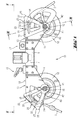
- Eine Umlenkvorrichtung einer Seilsägevorrichtung in Seitenansicht;
- Fig. 2
- die Umlenkvorrichtung in einer Aufsicht gem. Linie II-II in
Fig. 1 ; - Fig. 3
- einen Schnitt entlang der Linie III-III in
Fig. 1 ; - Fig. 4
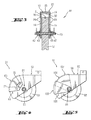
- ein zweites Ausführungsbeispiel einer Umlenkrollenvorrichtung in Seitenansicht; und
- Fig. 5
- ein drittes Ausführungsbeispiel einer Umlenkrollenvorrichtung in Seitenansicht.
- Grundsätzlich sind in den Figuren gleiche Teile mit den gleichen Bezugszeichen versehen.
- In den
Figuren 1 bis 3 ist eine Umlenkvorrichtung 11 einer Seilsägevorrichtung mit zwei Umlenkrollen 12 gezeigt, die an einem Trägerelement 6 festgelegt sind. Beide Umlenkrollen 12 sind im Wesentlichen gleich ausgebildet und weisen jeweils eine die jeweilige Umlenkrolle 12 bereichsweise umgebende, ortsfeste Schutzabdeckung 13 auf. Die Schutzabdeckung 13 weist bereichsweise im Schnitt quer zur Umlenkrolle 12 einen U-förmigen Querschnitt mit einem bezogen auf die Rollenachse 15 der Umlenkrolle 12 radialen Wandabschnitt 18 auf. Im Bereich eines freien Endes der Schenkel 14 der Schutzabdeckung 13 ist eine Durchführöffnung für die Lagerung der Rollenachse 15 der Umlenkrolle 12 vorgesehen. Über eine Festlegeeinrichtung 16 bzw. 17 ist die Schutzabdeckung 13 lösbar an dem Trägerelement 6 festgelegt. - Weiter ist bei jeder Umlenkrolle 12 ein Abdeckelement 23 mit einem in Bezug auf die Rollenachse 15 der Umlenkrolle 12 radial beabstandeten Wandabschnitt 25 vorgesehen, das verschwenkbar an der Schutzabdeckung 13 angeordnet ist. Das Abdeckelement 23 ist schwenkbar an der Rollenachse 15 der Umlenkrolle 12 gelagert. Das Abdeckelement 23 weist im Schnitt quer zur Umlenkrolle 12 ebenfalls eine U-förmige Ausgestaltung sowie im Bereich der freien Enden der Schenkel 24 des Abdeckelementes 23 jeweils eine Durchführöffnung für die Rollenachse 15 der Umlenkrolle 12 auf.
- Der radiale Abstand des radial beabstandeten Wandabschnitts 25 des Abdeckelementes 23 ist grösser als der radiale Abstand des radialen Wandabschnitts 18 der Schutzabdeckung 13 ausgebildet jeweils bezogen auf die Rollenachse 15 der Umlenkrolle 12.
- Zur Führung und Begrenzung des Verschwenkbereichs des Abdeckelementes 23 in Bezug auf die Schutzabdeckung 13 ist jeweils eine Führungseinrichtung 31 vorgesehen, die ein im Schenkel 24 des Abdeckelementes 23 angeordnetes, in einem bestimmten Abstand zur Rollenachse 15 der Umlenkrolle 12 bogenförmig verlaufendes Langloch 32 sowie ein von dem Schenkel 14 der Schutzabdeckung 13 abragendes sowie im Langloch 32 angeordnetes Anschlagelement 33 umfasst.
- Weiter ist an der Rollenachse 15 der Umlenkrolle 12 eine Fixiervorrichtung 41 zur Festlegung des Abdeckelementes 23 in der gewünschten Ausrichtung zur Schutzabdeckung 13 vorgesehen. Die Fixiervorrichtung 41 umfasst als Federelement 43 eine Tellerfeder, die zwischen einer an der Rollenachse 15 der Umlenkrolle 12 aufgeschraubten Befestigungsmutter 42 und der Aussenseite des Abdeckelementes 23 angeordnet ist. Beim Verspannen der Fixiervorrichtung 41 wirkt das Federelement 43 reibschlüssig auf das Abdeckelement 23 und fixiert dieses in der gewünschten Ausrichtung. Die Fixiervorrichtung 41 ist derart ausgebildet, dass auch in deren verspannten Zustand die Umlenkrolle 12 frei drehen kann.
- Jedes Abdeckelement 23 weist am freien, dem Sägeseil 7 zugewandten Ende 26 des radial zur Rollenachse 15 der Umlenkrolle 13 beabstandeten Wandabschnitts 25 eine Abrundung 27 auf.
- Die in
Figur 4 dargestellte Variante einer erfindungsgemässen Umlenkvorrichtung 51 einer Seilsägevorrichtung weist eine Umlenkrolle 52 auf, welche bereichsweise von einer ortsfesten Schutzabdeckung 53 sowie einem verschwenkbar an der Schutzabdeckung 53 angeordneten Abdeckelement 63 umgeben ist. Das Abdeckelement 63 weist im Schnitt quer zur Umlenkrolle 52 ebenfalls eine U-förmige Ausgestaltung sowie in den Schenkeln 64 ein eine Kulisse ausbildendes, gebogen verlaufendes Langloch 72 auf, das mit einem Fixiermittel 73, z. B. in Form einer an der ortsfesten Schutzabdeckung 53 angeordneten Schraube, eine Kulissenverbindung ausbildet. Die Kulissenverbindung ermöglicht ein einfaches Verschwenken des Abdeckelementes 63 bezogen auf die ortsfeste Schutzabdeckung 53 beziehungsweise auf die Rollenachse 55 der Umlenkrolle 52 und bildet gleichzeitig die Fixiervorrichtung 81 für das Abdeckelement 63 aus. - Die in
Figur 5 gezeigte, weitere Variante einer erfindungsgemässen Umlenkvorrichtung 91 einer Seilsägevorrichtung weist eine Umlenkrolle 92 auf, welche bereichsweise von einer ortsfesten Schutzabdeckung 93 sowie zwei verschwenkbar an der Schutzabdeckung 93 angeordneten Abdeckelemente 102 und 103 umgeben ist. Der radiale Abstand des radial beabstandeten Wandabschnitts 105 des Abdeckelementes 103 ist grösser als der radiale Abstand des radial beabstandeten Wandabschnitts 108 des Abdeckelementes 102 ausgebildet, wobei der radiale Abstand des radial beabstandeten Wandabschnitts 108 des Abdeckelementes 102 grösser als der radiale Abstand des radialen Wandabschnitts 98 der Schutzabdeckung 93 ausgebildet ist, jeweils bezogen auf die Rollenachse 95 der Umlenkrolle 92. Die Abdeckelemente 102 und 103 sind fächerartig zusammenschiebbar und ausbreitbar.
Claims (8)
- Umlenkvorrichtung einer Seilsägevorrichtung mit einer Umlenkrolle (12; 52; 92), die eine die Umlenkrolle (12; 52; 92) zumindest bereichsweise umgebende, ortsfeste Schutzabdeckung (13; 53; 93) sowie zumindest ein Abdeckelement (23; 63; 102, 103) aufweist, das entlang einer radial zur Rollenachse (15; 55; 95) der Umlenkrolle (12; 52; 92) beabstandeten Bahn versetzbar ist, dadurch gekennzeichnet, dass das Abdeckelement (23; 63; 102, 103) verschwenkbar an der Schutzabdeckung (13; 53; 93) angeordnet ist.
- Umlenkvorrichtung nach Anspruch 1, dadurch gekennzeichnet, dass das Abdeckelement (23; 102, 103) verschwenkbar an der Rollenachse (15; 95) der Umlenkrolle (12; 92) gelagert ist.
- Umlenkvorrichtung nach Anspruch 1 oder 2, dadurch gekennzeichnet, dass eine Fixiervorrichtung (41; 81) zur Festlegung des Abdeckelementes (23; 63) in der gewünschten Ausrichtung in Bezug auf die Schutzabdeckung (13; 53) vorgesehen ist.
- Umlenkvorrichtung nach Anspruch 3, dadurch gekennzeichnet, dass die Fixiervorrichtung (41) ein Federelement (43) umfasst.
- Umlenkvorrichtung nach einem der Ansprüche 1 bis 4, dadurch gekennzeichnet, dass zur Führung des Abdeckelementes (23) zu der Schutzabdeckung (13) eine Führungseinrichtung (31) für das Abdeckelement (23) vorgesehen ist.
- Umlenkvorrichtung nach Anspruch 5, dadurch gekennzeichnet, dass die Führungseinrichtung (31) ein Langloch (32) sowie ein im Langloch (32) angeordnetes Anschlagelement (33) umfasst.
- Umlenkvorrichtung nach Anspruch 6, dadurch gekennzeichnet, dass das Langloch (32) im Abdeckelement (23) und das Anschlagelement (33) an der Schutzabdeckung (13) vorgesehen ist.
- Umlenkvorrichtung nach einem der Ansprüche 1 bis 7, dadurch gekennzeichnet, dass das freie, dem Sägeseil (7) zugewandte Ende (26) eines radial zur Rollenachse (15) der Umlenkrolle (12) beabstandeten Wandabschnitts (25) des Abdeckelementes (23) abgerundet ist.
Applications Claiming Priority (1)
| Application Number | Priority Date | Filing Date | Title |
|---|---|---|---|
| DE200710000329 DE102007000329A1 (de) | 2007-06-14 | 2007-06-14 | Umlenkvorrichtung einer Seilsägevorrichtung |
Publications (2)
| Publication Number | Publication Date |
|---|---|
| EP2002913A1 true EP2002913A1 (de) | 2008-12-17 |
| EP2002913B1 EP2002913B1 (de) | 2011-07-06 |
Family
ID=39761078
Family Applications (1)
| Application Number | Title | Priority Date | Filing Date |
|---|---|---|---|
| EP20080103974 Active EP2002913B1 (de) | 2007-06-14 | 2008-05-15 | Umlenkvorrichtung für eine Seilsägevorrichtung |
Country Status (6)
| Country | Link |
|---|---|
| US (1) | US7878885B2 (de) |
| EP (1) | EP2002913B1 (de) |
| JP (1) | JP5416922B2 (de) |
| AT (1) | ATE515351T1 (de) |
| DE (1) | DE102007000329A1 (de) |
| NO (1) | NO336831B1 (de) |
Families Citing this family (4)
| Publication number | Priority date | Publication date | Assignee | Title |
|---|---|---|---|---|
| KR101510262B1 (ko) * | 2013-06-13 | 2015-04-10 | 주식회사 포스코 | 운송장치 |
| USD909164S1 (en) * | 2020-07-15 | 2021-02-02 | Yongkang Yizu Trading Co., Ltd | Rope saw |
| CN114393716B (zh) * | 2022-01-18 | 2023-09-01 | 长沙百川超硬材料工具有限公司 | 一种便于安装锯绳的防护罩及其组成的绳锯机 |
| EP4701971A1 (de) * | 2023-10-16 | 2026-03-04 | Wittur Holding GmbH | Riemenscheibenanordnung für einen aufzug |
Citations (2)
| Publication number | Priority date | Publication date | Assignee | Title |
|---|---|---|---|---|
| US4750468A (en) * | 1985-01-09 | 1988-06-14 | Bruno Micheletti | Machine for cutting blocks of stones in quarry |
| WO2004006654A1 (en) * | 2002-07-12 | 2004-01-22 | Plustech Oy | Sawing device and its safety system for precaution of a breaking saw chain |
Family Cites Families (4)
| Publication number | Priority date | Publication date | Assignee | Title |
|---|---|---|---|---|
| JP3016712B2 (ja) * | 1995-04-25 | 2000-03-06 | 株式会社コンセック | 鉄筋コンクリート構造物の切断装置 |
| JPH1029212A (ja) * | 1996-07-16 | 1998-02-03 | Tokyo Seimitsu Co Ltd | ワイヤソーのスラリ飛散防止カバー |
| JP3036674U (ja) * | 1996-10-09 | 1997-05-02 | 株式会社工務 | カッター |
| DE10148492A1 (de) * | 2001-10-01 | 2003-04-17 | Hilti Ag | Seilsäge |
-
2007
- 2007-06-14 DE DE200710000329 patent/DE102007000329A1/de not_active Withdrawn
-
2008
- 2008-05-15 EP EP20080103974 patent/EP2002913B1/de active Active
- 2008-05-15 AT AT08103974T patent/ATE515351T1/de active
- 2008-06-11 US US12/157,741 patent/US7878885B2/en active Active
- 2008-06-11 JP JP2008153046A patent/JP5416922B2/ja active Active
- 2008-06-12 NO NO20082624A patent/NO336831B1/no unknown
Patent Citations (3)
| Publication number | Priority date | Publication date | Assignee | Title |
|---|---|---|---|---|
| US4750468A (en) * | 1985-01-09 | 1988-06-14 | Bruno Micheletti | Machine for cutting blocks of stones in quarry |
| WO2004006654A1 (en) * | 2002-07-12 | 2004-01-22 | Plustech Oy | Sawing device and its safety system for precaution of a breaking saw chain |
| EP1528852B1 (de) | 2002-07-12 | 2006-04-05 | John Deere Forestry Oy | Sägevorrichtung und zugehöriges sicherheitssystem zum schutz vor einer reissenden sägekette |
Also Published As
| Publication number | Publication date |
|---|---|
| JP2008307897A (ja) | 2008-12-25 |
| DE102007000329A1 (de) | 2008-12-18 |
| US7878885B2 (en) | 2011-02-01 |
| NO20082624L (no) | 2008-12-15 |
| US20080314218A1 (en) | 2008-12-25 |
| JP5416922B2 (ja) | 2014-02-12 |
| ATE515351T1 (de) | 2011-07-15 |
| EP2002913B1 (de) | 2011-07-06 |
| NO336831B1 (no) | 2015-11-16 |
Similar Documents
| Publication | Publication Date | Title |
|---|---|---|
| EP3053684A1 (de) | Trennvorrichtung zum trennen eines zylindrischen werkstücks | |
| EP1206333A1 (de) | Winkelschleiferschutzhaube | |
| DE29916682U1 (de) | Anordnung zur Sicherung eines Bauteils | |
| EP2002913B1 (de) | Umlenkvorrichtung für eine Seilsägevorrichtung | |
| DE102005007766B3 (de) | Vorrichtung zum Zentrieren von miteinander zu verschweißenden Rohrstößen | |
| EP0504097A1 (de) | Höhenverstellbare Rohrabhängung | |
| DE7909078U1 (de) | Schutzhaube fuer ein motorisch angetriebenes handwerkzeug | |
| DE10055049C1 (de) | Vorrichtung zur Aufhängung eines Sägeblattes in einer Parallelogramm-Dekupiersäge | |
| DE102006035744B4 (de) | Vorrichtung zum automatischen Spannen einer Kette einer einen Kettenantrieb aufweisenden Kettensäge | |
| DE60007247T2 (de) | Klammer mit Schraubbefestigung für Förderband | |
| DE3700619C2 (de) | ||
| EP1849353B1 (de) | Haltevorrichtung für Baumteile zum Abtrennen derselben | |
| DE2814830C3 (de) | Ständer zur vertikalen Aufnahme von Stangen, Baumstämmen u.dgl., insbesondere Christbaumständer | |
| DE3930532C1 (en) | Fret saw with saw blade end clamped in bracket - has other blade end non-rotatably clamp by retainer, with both blade ends mutually twisted | |
| DE102017129301A1 (de) | Verbindungsanordnung | |
| DE10254006B3 (de) | Schnellspannklammer | |
| DE10131854B4 (de) | Klemmvorrichtung zur Personensicherung im Bergsport | |
| EP2612720A1 (de) | Sägeblatthalterung für auswechselbares Sägeblatt sowie Sägeblatt hierfür | |
| EP3162503B1 (de) | Kettenspannvorrichtung | |
| DE3006605C2 (de) | Lochbrenngerät | |
| DE10052610A1 (de) | Vorrichtung zur Einstellung der Schnitttiefe eines handgeführten Elektrowerkzeugs, Schutzhaube für ein handgeführtes Elektrowerkzeug sowie handgeführtes Elektrowerkzeug | |
| DE19501312B4 (de) | Halter für Trommeln, zur Verwendung an Trommelständern | |
| DE10163679C1 (de) | Dämpferklemme zur Befestigung eines Schwingungsdämpfers an einem Seil | |
| DE102009013984B4 (de) | Kettenspanner | |
| DE19843009B4 (de) | Sicherheitsvorrichtung für eine Kettensäge |
Legal Events
| Date | Code | Title | Description |
|---|---|---|---|
| PUAI | Public reference made under article 153(3) epc to a published international application that has entered the european phase |
Free format text: ORIGINAL CODE: 0009012 |
|
| AK | Designated contracting states |
Kind code of ref document: A1 Designated state(s): AT BE BG CH CY CZ DE DK EE ES FI FR GB GR HR HU IE IS IT LI LT LU LV MC MT NL NO PL PT RO SE SI SK TR |
|
| AX | Request for extension of the european patent |
Extension state: AL BA MK RS |
|
| 17P | Request for examination filed |
Effective date: 20090617 |
|
| 17Q | First examination report despatched |
Effective date: 20090708 |
|
| AKX | Designation fees paid |
Designated state(s): AT BE BG CH CY CZ DE DK EE ES FI FR GB GR HR HU IE IS IT LI LT LU LV MC MT NL NO PL PT RO SE SI SK TR |
|
| GRAP | Despatch of communication of intention to grant a patent |
Free format text: ORIGINAL CODE: EPIDOSNIGR1 |
|
| RTI1 | Title (correction) |
Free format text: DEFLECTION DEVICE FOR A WIRE SAW DEVICE |
|
| GRAS | Grant fee paid |
Free format text: ORIGINAL CODE: EPIDOSNIGR3 |
|
| GRAA | (expected) grant |
Free format text: ORIGINAL CODE: 0009210 |
|
| AK | Designated contracting states |
Kind code of ref document: B1 Designated state(s): AT BE BG CH CY CZ DE DK EE ES FI FR GB GR HR HU IE IS IT LI LT LU LV MC MT NL NO PL PT RO SE SI SK TR |
|
| REG | Reference to a national code |
Ref country code: GB Ref legal event code: FG4D Free format text: NOT ENGLISH |
|
| REG | Reference to a national code |
Ref country code: CH Ref legal event code: EP |
|
| REG | Reference to a national code |
Ref country code: IE Ref legal event code: FG4D Free format text: LANGUAGE OF EP DOCUMENT: GERMAN |
|
| REG | Reference to a national code |
Ref country code: DE Ref legal event code: R096 Ref document number: 502008004100 Country of ref document: DE Effective date: 20110825 |
|
| REG | Reference to a national code |
Ref country code: SE Ref legal event code: TRGR |
|
| REG | Reference to a national code |
Ref country code: NL Ref legal event code: VDEP Effective date: 20110706 |
|
| PG25 | Lapsed in a contracting state [announced via postgrant information from national office to epo] |
Ref country code: SI Free format text: LAPSE BECAUSE OF FAILURE TO SUBMIT A TRANSLATION OF THE DESCRIPTION OR TO PAY THE FEE WITHIN THE PRESCRIBED TIME-LIMIT Effective date: 20110706 |
|
| PG25 | Lapsed in a contracting state [announced via postgrant information from national office to epo] |
Ref country code: IS Free format text: LAPSE BECAUSE OF FAILURE TO SUBMIT A TRANSLATION OF THE DESCRIPTION OR TO PAY THE FEE WITHIN THE PRESCRIBED TIME-LIMIT Effective date: 20111106 Ref country code: FI Free format text: LAPSE BECAUSE OF FAILURE TO SUBMIT A TRANSLATION OF THE DESCRIPTION OR TO PAY THE FEE WITHIN THE PRESCRIBED TIME-LIMIT Effective date: 20110706 Ref country code: NL Free format text: LAPSE BECAUSE OF FAILURE TO SUBMIT A TRANSLATION OF THE DESCRIPTION OR TO PAY THE FEE WITHIN THE PRESCRIBED TIME-LIMIT Effective date: 20110706 Ref country code: NO Free format text: LAPSE BECAUSE OF FAILURE TO SUBMIT A TRANSLATION OF THE DESCRIPTION OR TO PAY THE FEE WITHIN THE PRESCRIBED TIME-LIMIT Effective date: 20111006 Ref country code: LT Free format text: LAPSE BECAUSE OF FAILURE TO SUBMIT A TRANSLATION OF THE DESCRIPTION OR TO PAY THE FEE WITHIN THE PRESCRIBED TIME-LIMIT Effective date: 20110706 Ref country code: HR Free format text: LAPSE BECAUSE OF FAILURE TO SUBMIT A TRANSLATION OF THE DESCRIPTION OR TO PAY THE FEE WITHIN THE PRESCRIBED TIME-LIMIT Effective date: 20110706 Ref country code: PT Free format text: LAPSE BECAUSE OF FAILURE TO SUBMIT A TRANSLATION OF THE DESCRIPTION OR TO PAY THE FEE WITHIN THE PRESCRIBED TIME-LIMIT Effective date: 20111107 |
|
| REG | Reference to a national code |
Ref country code: IE Ref legal event code: FD4D |
|
| PG25 | Lapsed in a contracting state [announced via postgrant information from national office to epo] |
Ref country code: PL Free format text: LAPSE BECAUSE OF FAILURE TO SUBMIT A TRANSLATION OF THE DESCRIPTION OR TO PAY THE FEE WITHIN THE PRESCRIBED TIME-LIMIT Effective date: 20110706 Ref country code: LV Free format text: LAPSE BECAUSE OF FAILURE TO SUBMIT A TRANSLATION OF THE DESCRIPTION OR TO PAY THE FEE WITHIN THE PRESCRIBED TIME-LIMIT Effective date: 20110706 Ref country code: CY Free format text: LAPSE BECAUSE OF FAILURE TO SUBMIT A TRANSLATION OF THE DESCRIPTION OR TO PAY THE FEE WITHIN THE PRESCRIBED TIME-LIMIT Effective date: 20110706 Ref country code: GR Free format text: LAPSE BECAUSE OF FAILURE TO SUBMIT A TRANSLATION OF THE DESCRIPTION OR TO PAY THE FEE WITHIN THE PRESCRIBED TIME-LIMIT Effective date: 20111007 |
|
| PG25 | Lapsed in a contracting state [announced via postgrant information from national office to epo] |
Ref country code: CZ Free format text: LAPSE BECAUSE OF FAILURE TO SUBMIT A TRANSLATION OF THE DESCRIPTION OR TO PAY THE FEE WITHIN THE PRESCRIBED TIME-LIMIT Effective date: 20110706 Ref country code: IE Free format text: LAPSE BECAUSE OF FAILURE TO SUBMIT A TRANSLATION OF THE DESCRIPTION OR TO PAY THE FEE WITHIN THE PRESCRIBED TIME-LIMIT Effective date: 20110706 Ref country code: SK Free format text: LAPSE BECAUSE OF FAILURE TO SUBMIT A TRANSLATION OF THE DESCRIPTION OR TO PAY THE FEE WITHIN THE PRESCRIBED TIME-LIMIT Effective date: 20110706 |
|
| PLBE | No opposition filed within time limit |
Free format text: ORIGINAL CODE: 0009261 |
|
| STAA | Information on the status of an ep patent application or granted ep patent |
Free format text: STATUS: NO OPPOSITION FILED WITHIN TIME LIMIT |
|
| PG25 | Lapsed in a contracting state [announced via postgrant information from national office to epo] |
Ref country code: RO Free format text: LAPSE BECAUSE OF FAILURE TO SUBMIT A TRANSLATION OF THE DESCRIPTION OR TO PAY THE FEE WITHIN THE PRESCRIBED TIME-LIMIT Effective date: 20110706 Ref country code: EE Free format text: LAPSE BECAUSE OF FAILURE TO SUBMIT A TRANSLATION OF THE DESCRIPTION OR TO PAY THE FEE WITHIN THE PRESCRIBED TIME-LIMIT Effective date: 20110706 |
|
| 26N | No opposition filed |
Effective date: 20120411 |
|
| PG25 | Lapsed in a contracting state [announced via postgrant information from national office to epo] |
Ref country code: DK Free format text: LAPSE BECAUSE OF FAILURE TO SUBMIT A TRANSLATION OF THE DESCRIPTION OR TO PAY THE FEE WITHIN THE PRESCRIBED TIME-LIMIT Effective date: 20110706 |
|
| REG | Reference to a national code |
Ref country code: DE Ref legal event code: R097 Ref document number: 502008004100 Country of ref document: DE Effective date: 20120411 |
|
| BERE | Be: lapsed |
Owner name: HILTI AKTIENGESELLSCHAFT Effective date: 20120531 |
|
| PG25 | Lapsed in a contracting state [announced via postgrant information from national office to epo] |
Ref country code: MC Free format text: LAPSE BECAUSE OF NON-PAYMENT OF DUE FEES Effective date: 20120531 |
|
| PG25 | Lapsed in a contracting state [announced via postgrant information from national office to epo] |
Ref country code: BE Free format text: LAPSE BECAUSE OF NON-PAYMENT OF DUE FEES Effective date: 20120531 |
|
| PG25 | Lapsed in a contracting state [announced via postgrant information from national office to epo] |
Ref country code: ES Free format text: LAPSE BECAUSE OF FAILURE TO SUBMIT A TRANSLATION OF THE DESCRIPTION OR TO PAY THE FEE WITHIN THE PRESCRIBED TIME-LIMIT Effective date: 20111017 |
|
| PG25 | Lapsed in a contracting state [announced via postgrant information from national office to epo] |
Ref country code: BG Free format text: LAPSE BECAUSE OF FAILURE TO SUBMIT A TRANSLATION OF THE DESCRIPTION OR TO PAY THE FEE WITHIN THE PRESCRIBED TIME-LIMIT Effective date: 20111006 |
|
| PG25 | Lapsed in a contracting state [announced via postgrant information from national office to epo] |
Ref country code: MT Free format text: LAPSE BECAUSE OF FAILURE TO SUBMIT A TRANSLATION OF THE DESCRIPTION OR TO PAY THE FEE WITHIN THE PRESCRIBED TIME-LIMIT Effective date: 20110706 |
|
| PG25 | Lapsed in a contracting state [announced via postgrant information from national office to epo] |
Ref country code: TR Free format text: LAPSE BECAUSE OF FAILURE TO SUBMIT A TRANSLATION OF THE DESCRIPTION OR TO PAY THE FEE WITHIN THE PRESCRIBED TIME-LIMIT Effective date: 20110706 |
|
| PG25 | Lapsed in a contracting state [announced via postgrant information from national office to epo] |
Ref country code: LU Free format text: LAPSE BECAUSE OF NON-PAYMENT OF DUE FEES Effective date: 20120515 |
|
| PG25 | Lapsed in a contracting state [announced via postgrant information from national office to epo] |
Ref country code: HU Free format text: LAPSE BECAUSE OF FAILURE TO SUBMIT A TRANSLATION OF THE DESCRIPTION OR TO PAY THE FEE WITHIN THE PRESCRIBED TIME-LIMIT Effective date: 20080515 |
|
| REG | Reference to a national code |
Ref country code: FR Ref legal event code: PLFP Year of fee payment: 9 |
|
| REG | Reference to a national code |
Ref country code: FR Ref legal event code: PLFP Year of fee payment: 10 |
|
| REG | Reference to a national code |
Ref country code: FR Ref legal event code: PLFP Year of fee payment: 11 |
|
| PGFP | Annual fee paid to national office [announced via postgrant information from national office to epo] |
Ref country code: DE Payment date: 20250521 Year of fee payment: 18 |
|
| PGFP | Annual fee paid to national office [announced via postgrant information from national office to epo] |
Ref country code: GB Payment date: 20250530 Year of fee payment: 18 |
|
| PGFP | Annual fee paid to national office [announced via postgrant information from national office to epo] |
Ref country code: IT Payment date: 20250527 Year of fee payment: 18 |
|
| PGFP | Annual fee paid to national office [announced via postgrant information from national office to epo] |
Ref country code: FR Payment date: 20250528 Year of fee payment: 18 |
|
| PGFP | Annual fee paid to national office [announced via postgrant information from national office to epo] |
Ref country code: CH Payment date: 20250601 Year of fee payment: 18 |
|
| PGFP | Annual fee paid to national office [announced via postgrant information from national office to epo] |
Ref country code: AT Payment date: 20250522 Year of fee payment: 18 |
|
| PGFP | Annual fee paid to national office [announced via postgrant information from national office to epo] |
Ref country code: SE Payment date: 20250521 Year of fee payment: 18 |