EP2002938B1 - Outil d'impact avec réducteur de vibrations - Google Patents
Outil d'impact avec réducteur de vibrations Download PDFInfo
- Publication number
- EP2002938B1 EP2002938B1 EP08010832.7A EP08010832A EP2002938B1 EP 2002938 B1 EP2002938 B1 EP 2002938B1 EP 08010832 A EP08010832 A EP 08010832A EP 2002938 B1 EP2002938 B1 EP 2002938B1
- Authority
- EP
- European Patent Office
- Prior art keywords
- crank
- tool
- crank mechanism
- opening
- crank shaft
- Prior art date
- Legal status (The legal status is an assumption and is not a legal conclusion. Google has not performed a legal analysis and makes no representation as to the accuracy of the status listed.)
- Active
Links
Images






Classifications
-
- B—PERFORMING OPERATIONS; TRANSPORTING
- B25—HAND TOOLS; PORTABLE POWER-DRIVEN TOOLS; MANIPULATORS
- B25D—PERCUSSIVE TOOLS
- B25D17/00—Details of, or accessories for, portable power-driven percussive tools
- B25D17/24—Damping the reaction force
-
- B—PERFORMING OPERATIONS; TRANSPORTING
- B25—HAND TOOLS; PORTABLE POWER-DRIVEN TOOLS; MANIPULATORS
- B25D—PERCUSSIVE TOOLS
- B25D11/00—Portable percussive tools with electromotor or other motor drive
- B25D11/06—Means for driving the impulse member
- B25D11/12—Means for driving the impulse member comprising a crank mechanism
- B25D11/125—Means for driving the impulse member comprising a crank mechanism with a fluid cushion between the crank drive and the striking body
-
- B—PERFORMING OPERATIONS; TRANSPORTING
- B25—HAND TOOLS; PORTABLE POWER-DRIVEN TOOLS; MANIPULATORS
- B25D—PERCUSSIVE TOOLS
- B25D17/00—Details of, or accessories for, portable power-driven percussive tools
- B25D17/06—Hammer pistons; Anvils ; Guide-sleeves for pistons
-
- B—PERFORMING OPERATIONS; TRANSPORTING
- B25—HAND TOOLS; PORTABLE POWER-DRIVEN TOOLS; MANIPULATORS
- B25D—PERCUSSIVE TOOLS
- B25D2211/00—Details of portable percussive tools with electromotor or other motor drive
- B25D2211/003—Crossed drill and motor spindles
-
- B—PERFORMING OPERATIONS; TRANSPORTING
- B25—HAND TOOLS; PORTABLE POWER-DRIVEN TOOLS; MANIPULATORS
- B25D—PERCUSSIVE TOOLS
- B25D2217/00—Details of, or accessories for, portable power-driven percussive tools
- B25D2217/0011—Details of anvils, guide-sleeves or pistons
- B25D2217/0019—Guide-sleeves
-
- B—PERFORMING OPERATIONS; TRANSPORTING
- B25—HAND TOOLS; PORTABLE POWER-DRIVEN TOOLS; MANIPULATORS
- B25D—PERCUSSIVE TOOLS
- B25D2217/00—Details of, or accessories for, portable power-driven percussive tools
- B25D2217/0073—Arrangements for damping of the reaction force
- B25D2217/0076—Arrangements for damping of the reaction force by use of counterweights
- B25D2217/0088—Arrangements for damping of the reaction force by use of counterweights being mechanically-driven
-
- B—PERFORMING OPERATIONS; TRANSPORTING
- B25—HAND TOOLS; PORTABLE POWER-DRIVEN TOOLS; MANIPULATORS
- B25D—PERCUSSIVE TOOLS
- B25D2217/00—Details of, or accessories for, portable power-driven percussive tools
- B25D2217/0073—Arrangements for damping of the reaction force
- B25D2217/0076—Arrangements for damping of the reaction force by use of counterweights
- B25D2217/0092—Arrangements for damping of the reaction force by use of counterweights being spring-mounted
-
- B—PERFORMING OPERATIONS; TRANSPORTING
- B25—HAND TOOLS; PORTABLE POWER-DRIVEN TOOLS; MANIPULATORS
- B25D—PERCUSSIVE TOOLS
- B25D2250/00—General details of portable percussive tools; Components used in portable percussive tools
- B25D2250/035—Bleeding holes, e.g. in piston guide-sleeves
-
- B—PERFORMING OPERATIONS; TRANSPORTING
- B25—HAND TOOLS; PORTABLE POWER-DRIVEN TOOLS; MANIPULATORS
- B25D—PERCUSSIVE TOOLS
- B25D2250/00—General details of portable percussive tools; Components used in portable percussive tools
- B25D2250/065—Details regarding assembling of the tool
Definitions
- the present invention relates to a vibration reducing technique in an impact tool which drives a tool bit, such as a hammer and a hammer drill.
- WO2005/105386 discloses an electric hammer having a vibration reducing mechanism.
- the known hammer has a dynamic vibration reducer, wherein a crank mechanism is utilized to actively drive a weight of the dynamic vibration reducer to reduce vibration caused during hammering operation.
- WO 2004/082897 A1 relates to a vibration reduction apparatus for use in a power tool and discloses an impact tool with the features of the preamble of claim 1 in combination.
- an impact tool having the feature of claim 1.
- Such an impact tool performs a predetermined hammering operation on a workpiece by a striking movement of a tool bit in its axial direction.
- the impact tool includes a tool body, a cylinder housed within the tool body, a dynamic vibration reducer and a mechanical vibration mechanism.
- the "predetermined hammering operation" in this invention suitably includes not only a hammering operation in which the tool bit performs only a striking movement in its axial direction, but a hammer drill operation in which it performs a striking movement in its axial direction and a rotation around its axis.
- the dynamic vibration reducer in this invention has a weight that can linearly move under a biasing force of an elastic element, and the dynamic vibration reducer reduces vibration of the tool body during hammering operation by the movement of the weight in the axial direction of the tool bit. It is at least necessary for the weight as an element of the dynamic vibration reducer to be acted upon by the biasing force of the elastic element. The weight may further be acted upon by a damping force of a damping element.
- the "elastic element” in this invention typically comprises a spring.
- the mechanical vibration mechanism actively drives the weight by applying external force other than vibration of the tool body to the weight via the elastic element. By thus actively driving the weight via the mechanical vibration mechanism and forcibly vibrating the dynamic vibration reducer, the dynamic vibration reducer can be steadily actuated regardless of the magnitude of vibration on the impact tool.
- the weight and the elastic element are disposed on the axis of the tool bit and between an inner wall surface of the tool body and an outer wall surface of the cylinder in such a manner as to cover at least part of the outer wall surface of the cylinder in the circumferential direction.
- the manner of "covering at least part of the outer wall surface of the cylinder in the circumferential direction" widely includes, as for the weight, the manner in which the weight has a cylindrical body which is circular, elliptical or polygonal in section and covers the entire outer wall surface of the cylinder in the circumferential direction, and the manner in which the weight has a cylindrical body which has a cut in part in the circumferential direction, such as a body generally C-shaped in section, and as for the elastic element, it represents the manner in which a coil spring is annularly disposed outside the cylinder.
- the centers of gravity of the weight and the elastic element can be placed substantially on the axis ofthe tool bit.
- a couple, or force of rotation around an axis extending transverse to the axial direction of the tool bit can be prevented from being generated when the weight moves in the axial direction of the tool bit.
- the existing space can be utilized to dispose the vibration reducing mechanism, which is effective in reducing the size ofthe impact tool.
- the impact tool further includes an actuating mechanism that linearly drives the tool bit.
- the actuating mechanism includes a motor, a striking element that linearly moves in the axial direction ofthe tool bit in such a manner as to cause the tool bit to linearly move, and a first crank mechanism that converts a rotating output of the motor into linear motion and thereby drives the striking element.
- the mechanical vibration mechanism includes a second crank mechanism that converts rotation of the first crank mechanism into linear motion and thereby drives the sliding element. Further, the second crank mechanism is rotationally driven by the motor via the first crank mechanism.
- Both the striking element and the sliding element can be driven by the single motor, and thus a rational driving system can be provided.
- the impact tool further includes an opening that is formed in the tool body and provided as a hole through which the first crank mechanism is mounted within the tool body, and a covering member that can be mounted on the opening from outside the tool body in such a manner as to close the opening.
- the first crank mechanism has a crank shaft that is rotatably disposed within the tool body and faces the opening.
- the second crank mechanism has a crank shaft that is rotatably mounted to the covering member and opposed to the crank shaft of the first crank mechanism.
- a concave portion is formed in one of opposed ends of the crank shafts of the first and second crank mechanisms, and a convex portion is formed on the other of the opposed ends of the crank shafts and can engage with the concave portion.
- crank shaft of the first crank mechanism and the crank shaft of the second crank mechanism are interconnected by engagement between the concave portion and the convex portion such that rotation of the crank shaft of the first crank mechanism can be transmitted to the crank shaft of the second crank mechanism.
- the manner of being “opposed” in this invention preferably represents the manner of being opposed substantially on the same axis.
- the second crank mechanism is mounted on the covering member for closing the opening, and when the covering member is mounted on the opening, the crank shaft of the first crank mechanism and the crank shaft of the second crank mechanism are interconnected by engagement between the concave portion and the convex portion such that rotation can be transmitted.
- the weight is disposed on the tool body such that the weight can move along the inner wall surface of the tool body in the axial direction of the tool bit.
- the linear movement of the weight along the inner wall surface of the tool body can be stabilized.
- the weight and the elastic element which are disposed on the tool body side can be arranged out of contact with the outer wall surface of the cylinder. Therefore, if such a construction is applied to an impact tool of the type, for example, in which the striking element is driven via pressure fluctuations of air within the cylinder and strikes the tool bit, the weight can be avoided from having an adverse effect on the air vent which is formed in the cylinder in order to provide communication between the air chamber and the outside.
- the impact tool may include a driving element that linearly moves in the axial direction ofthe tool bit within the cylinder, a striking element that linearly moves in the axial direction of the tool bit within the cylinder, and an air chamber defined between the driving element and the striking element within the cylinder.
- the striking element is caused to linearly move via pressure fluctuations ofthe air chamber as a result, ofthe linear movement ofthe driving element and strikes the tool bit, whereby the predetermined hammering operation is performed on the workpiece.
- the impact tool may further include a ventilation part that is formed in the cylinder and provides communication between the air chamber and the outside in order to regulate pressure of the air chamber so as to achieve smooth movement of the striking element, and a ventilation part opening-closing member that is disposed outside the cylinder and can slide in the axial direction of the tool bit.
- the ventilation part opening-closing member controls opening and closing of the ventilation part by moving between an open position for opening the ventilation part and a closed position for closing the ventilation part at a predetermined timing.
- the timing of opening and closing the ventilation part, or the time at which the ventilation part is switched from the closed position to the open position during striking movement of the striking element and the time at which the ventilation part is switched from the open position to the closed position during suction of the striking element can be arbitrarily adjusted in the relationship with the position of the striking element.
- the ventilation part can be opened only when necessary.
- the pressure of the air chamber can be controlled such that, during striking movement of the striking element, optimum striking speed is provided for the striking element, and during suction of the striking element, optimum suction force acts upon the striking element.
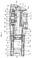
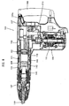
- FIG. 1 shows an entire electric hammer 101 as a representative embodiment of the impact tool according to the present invention.
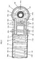
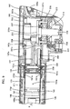
- FIGS. 2 , 4 and 6 are enlarged sectional views each showing an essential part of the hammer.
- FIG. 2 shows the state in which a slide sleeve for forcibly moving a dynamic vibration reducer is substantially in an intermediate position.
- FIGS. 4 and 5 show the state in which the slide sleeve is in a front end position
- FIGS. 6 and 7 show the state in which the slide sleeve is in a rear end position
- the hammer 101 of this embodiment includes a body 103, a hammer bit 119 detachably coupled to the tip end region (on the left side as viewed in FIG. 1 ) of the body 103 via a tool holder 137, and a handgrip 109 that is connected to the body 103 on the side opposite the hammer bit 119 and designed to be held by a user.
- the body 103 and the hammer bit 119 are features that correspond to the "tool body” and the "tool bit", respectively, according to the present invention.
- the hammer bit 119 is held by the tool holder 137 such that it is allowed to reciprocate with respect to the tool holder 137 in its axial direction and prevented from rotating with respect to the tool holder 137 in its circumferential direction.
- the side of the hammer bit 119 is taken as the front side and the side of the handgrip 109 as the rear side.
- the body 103 includes a motor housing 105 that houses a driving motor 111, and a gear housing 107 that houses a first motion converting mechanism 113 and a second motion converting mechanism 116, and a barrel housing 108 that houses a striking mechanism 115.
- the rotating output of the driving motor 111 is appropriately converted into linear motion via the first motion converting mechanism 113 and transmitted to the striking element 115. Then, an impact force is generated in the axial direction of the hammer bit 119 via the striking element 115. Further; the rotating output of the driving motor 111 is transmitted to the second motion converting mechanism 116 via the first motion converting mechanism 113 and converted into linear motion by the second motion converting mechanism 116.
- the linear motion then serves as a driving force for forcibly vibrating a dynamic vibration reducer 171 which will be described below.
- the first motion converting mechanism 113 and the striking mechanism 115 are features that correspond to the "actuating mechanism", and the second motion converting mechanism 116 corresponds to the "mechanical vibration mechanism” according to this invention.
- the driving motor 111 is a feature that corresponds to the "motor” according to this invention. Further, a slide switch 109a is provided on the handgrip 109 and can be slid by the user to drive the driving motor 111.
- the first motion converting mechanism 113 includes a driving gear 121 that is rotated in a horizontal plane by the driving motor 111 (see FIG. 1 ), a first crank shaft 125 integrally having a driven gear 123 that engages with the driving gear 121, a connecting member in the form of a crank arm 127 that is loosely connected at its one end to the first crank shaft 125 via an eccentric pin 126 in a position displaced a predetermined distance from the center of rotation of the first crank shaft 125, and a driving element in the form of a piston 129 mounted to the other end of the crank arm 127 via a connecting shaft 128.
- the first crank shaft 125, the eccentric pin 126, the crank arm 127 and the piston 129 form a first crank mechanism.
- the striking mechanism 115 includes a striking element in the form of a striker 143 that is slidably disposed within the bore of the cylinder 141, and an intermediate element in the form of an impact bolt 145 that is slidably disposed within the tool holder 137 and transmits the kinetic energy of the striker 143 to the hammer bit 119.
- An air chamber 141a is defined between the piston 129 and the striker 143 within the cylinder 141.
- the striker 143 is driven via the action of an air spring of the air chamber 141a of the cylinder 141 which is caused by sliding movement of the piston 129.
- the striker 143 then collides with (strikes) the intermediate element in the form of the impact bolt 145 that is slidably disposed within the tool holder 137 and transmits the striking force to the hammer bit 119 via the impact bolt 145.
- the cylinder 141 is disposed coaxially with the hammer bit 119. Therefore, the piston 129 and the striker 143 linearly move on the same axis as the hammer bit 119. Further, the cylinder 141 is inserted from the front into the bore of a cylindrical cylinder holding portion 107a formed in the front region of the gear housing 107 and held there, and is housed within the barrel housing 108 joined to the gear housing 107.
- the dynamic vibration reducer 171 that reduces vibration of the body 103 during hammering operation and the second motion converting mechanism 116 that forcibly vibrates the dynamic vibration reducer 171 by actively driving a weight 173 of the dynamic vibration reducer 171 will now be described.
- forcibly vibrating the dynamic vibration reducer 171 is referred to as forced vibration.
- the dynamic vibration reducer 171 is provided in the inner space of the barrel housing 108 and mainly includes a cylindrical weight 173 annularly arranged outside the cylinder 141 and front and rear biasing springs 175F, 175R disposed on the front and rear sides of the weight 173 in the axial direction of the hammer bit.
- the biasing springs 175F, 175R are features that correspond to the "elastic element" according to this invention.
- the front and rear biasing springs 175F, 175R exert a spring force on the weight 173 in a direction toward each other when the weight 173 moves in the axial direction of the hammer bit 119.
- the weight 173 is arranged such that its center (of gravity) coincides with the axis of the hammer bit 119 and can freely slide with its outer wall surface held in contact with the inner wall surface (cylindrical surface) of the barrel housing 108.
- the front and rear biasing springs 175F, 175R are formed by compression coil springs and, like the weight 173, they are arranged such that each of their centers coincides with the axis ofthe hammer bit 119.
- One end (rear end) of the rear biasing spring 175R is held in contact with a front surface of the flange 151a of the slide sleeve 151, while the other end (front end) is held in contact with the axial rear end of the weight 173.
- one end (rear end) of the front biasing spring 175F is held in contact with the axial front end of the weight 173, while the other end (front end) is held in contact with a stepped surface 108a ofthe barrel housing 108.
- the slide sleeve 151 forms an input member that inputs the driving force of the second motion converting mechanism 116 into the weight 173 via the rear biasing spring 175R.
- the slide sleeve 151 is fitted on the cylinder 141 such that it can slide in the axial direction ofthe hammer bit, and the slide sleeve 151 is slid by the second motion converting mechanism 116.
- the slide sleeve 151 is a feature that corresponds to the "sliding element" according to this invention.
- An air vent 141b is formed in the cylinder 141 in order to regulate pressure of the air chamber 141a and provides communication between the air chamber 141a and the outside.
- the slide sleeve 151 In order to prevent the slide sleeve 151 fitted on the cylinder 141 from always closing the air vent 141b, the slide sleeve 151 includes an annular space 151b that always communicates with the air vent 141b, and a plurality of communication holes 151c that radially extend through the slide sleeve 151 and provide communication between the space 151 b and the outside.
- the second motion converting mechanism 116 is disposed above the first motion converting mechanism 113.
- the second motion converting mechanism 116 mainly includes a second crank shaft 153 that is rotationally driven in a horizontal plane by rotation of the eccentric pin 126 of the first motion converting mechanism 113, an eccentric shaft portion 155 integrally formed with the second crank shaft 153, a connecting plate 157 that is caused to reciprocate in the axial direction of the hammer bit by rotation of the eccentric shaft portion 155, and an actuating member in the form of right and left straight rods 159 that linearly move together with the connecting plate 157 and moves the slide sleeve 151 forward.
- the second crank shaft 153, the eccentric shaft portion 155 and the connecting plate 157 form the second crank mechanism which is a feature that corresponds to the "second crank mechanism" according to this invention.
- the second crank shaft 153 is coaxially opposed to the first crank shaft 125.
- the second crank shaft 153 has a disk-like portion 153a on its axial lower end.
- a recess (groove) 153b is formed in the lower surface of the disk-like portion 153a in a position displaced from the center of rotation of the second crank shaft 153.
- the recess 153b is engaged with a protruding end 126a of the eccentric pin 126 of the first motion converting mechanism 113.
- the recess 153b and the protruding end 126a are features that correspond to the "concave portion" and the "convex portion", respectively, according to this invention.
- the second crank shaft 153 is rotationally driven by a driving force that is inputted from the first crank shaft 125 via engagement between the recess 153b and the protruding end 126.
- An opening 107b to be used for mounting the first motion converting mechanism 113 is formed in the gear housing 107 above the first motion converting mechanism 113.
- the second crank mechanism is mounted on a crank cap 163 which is removably fitted over the opening 107b.
- the crank cap 163 is a feature that corresponds to the "covering member" according to this invention.
- the second crank shaft 153 is rotatably supported on the crank cap 163 via a bearing 165.
- the eccentric shaft portion 155 has a circular shape of which center is displaced a predetermined distance from the center of rotation of the second crank shaft 153.
- the connecting plate 157 is engaged with a ring 155a that is fitted on the eccentric shaft portion 155, via an elliptical hole 157a elongated in a direction transverse to the axial direction of the hammer bit. Further, the connecting plate 157 is guided by front and rear guide pins 156 mounted to the crank cap 163 in such a manner as to linearly move in the axial direction of the hammer bit.
- front and rear guide grooves 157c are formed in the connecting plate 157 and extend in the axial direction of the hammer bit, and the guide grooves 157c are slidably engaged with the associated guide pins 156.
- the right and left rods 159 are slidably fitted into respective guide holes 107c that are formed through the cylinder holding portion 107a of the gear housing 107 in the axial direction of the hammer bit.
- One axial end (rear end) of each of the rods 159 is held in contact with a planar front surface 157b of the connecting plate 157, while the other axial end (front end) is held in contact with a rear end surface of the slide sleeve 151.
- the second crank shaft 153 and the connecting plate 157 which form the second crank mechanism are mounted to the crank cap 163 before the crank cap 163 is mounted on the opening 107b of the gear housing 107.
- the connecting plate 157 is held between the inner wall surface of the crank cap 163 and the disk-like portion 153a of the second crank shaft 153, so that the connecting plate 157 is prevented from moving in the axial direction of the second crank shaft 153 (in the vertical direction).
- the crank cap 163 with the second crank shaft 153 and the connecting plate 157 mounted thereto is fitted over the opening 107b from outside (above) the gear housing 107 and fastened to the gear housing 107 by a plurality of screws 163a.
- the recess 153b formed in the disk-like portion 153a of the second crank shaft 153 is engaged with the protruding end 126a of the eccentric pin 126 of the first crank mechanism which is already mounted within the gear housing 107, and the rear end of the rod 159 is brought into contact with the front surface 157b of the connecting plate 157.
- the first and second crank mechanisms are assembled in a mechanically interconnected manner such that the rotating force can be transmitted.
- the kinetic energy of the striker 143 which is caused by the collision with the impact boh 145 is transmitted to the hammer bit 119.
- the hammer bit 119 performs a striking movement in its axial direction, and the hammering operation is performed on the workpiece.
- impulsive and cyclic vibration is caused in the body 103 in the axial direction of the hammer bit.
- Main vibration of the body 103 which is to be reduced is a compressing reaction force which is produced when the piston 129 and the striker 143 compress air within the air chamber 141a, and a striking reaction force which is produced with a slight time lag behind the compressing reaction force when the striker 143 strikes the hammer bit 119 via the impact bolt 145.
- the weight 173 and the biasing springs 175F, 175R serve as vibration reducing elements in the dynamic vibration reducer 171 and cooperate to passively reduce vibration of the body 103 of the hammer 101.
- the above-mentioned vibration which is caused in the body 103 of the hammer 101 can be effectively alleviated or reduced.
- vibration of the body 103 can be more effectively reduced by forced vibration of the dynamic vibration reducer 171.
- the second crank shaft 153 that is engaged with the protruding end 126a of the eccentric pin 126 via the recess 153b is caused to rotate at the same speed as the first crank shaft 125.
- the connecting plate 157 engaged with the eccentric shaft portion 155 is caused to reciprocate in the axial direction of the hammer bit 119.
- FIGS. 2 and 3 show the state in which the slide sleeve 151 that moves in the longitudinal direction is substantially in its intermediate position.
- FIGS. 4 and 5 show the state in which the slide sleeve 151 is in its front end position
- FIGS. 6 and 7 show the state in which the slide sleeve 151 is in its rear end position.
- the weight 173 of the dynamic vibration reducer 171 is actively driven via the biasing springs 175F, 175R and causes the dynamic vibration reducer 171 to be forcibly vibrated.
- the dynamic vibration reducer 171 serves as an active vibration reducing mechanism in which the weight 173 is actively driven. Therefore, the vibration which is caused in the body 103 during hammering operation can be further effectively reduced or alleviated. As a result, a sufficient vibration reducing function can be ensured even in operations of the type in which, although vibration reduction is highly required, only a small amount of vibration is inputted to the dynamic vibration reducer 171 and the dynamic vibration reducer 171 does not sufficiently function, particularly, for example, in a hammering operation which is performed with the user's strong pressing force applied to the body 103 (force of pressing the hammer bit 119 against the workpiece).
- a spring receiving member in the form of the slide sleeve 151 is driven via the second crank mechanism which is formed by the eccentric shaft portion 155 and the connecting plate 157, and the weight 173 is actively driven via the rear biasing spring 175R.
- the timing of driving the weight 173 with respect to the timing of driving the piston 129 (the striker 143) by the first crank mechanism, or the crank phase of the second crank mechanism can be adjusted such that, when the striker 143 is caused to move forward via pressure fluctuations of the air chamber 141a and strikes the hammer bit 119 via the impact bolt 145, the weight 173 of the dynamic vibration reducer 171 counteracts impulsive vibration caused in the body 103 or linearly moves in a direction opposite to the intermediate region of either one or both of the above-mentioned compressing reaction force and the striking reaction force produced immediately after the compressing reaction force.
- the linear movement of the weight 173 can be timed to coincide with generation of a large amount of vibration during hammering operation, so that the vibration reducing function of the weight 173 can be performed in an optimum manner.
- the weight 173 and the biasing springs 175F, 175R which form the dynamic vibration reducer 171 are annularly arranged outside the cylinder 141.
- the space between the outer periphery of the cylinder 141 and the inner periphery of the barrel housing 108 can be effectively utilized to dispose the vibration reducing mechanism, which is effective in reducing the size of the electric hammer 101.
- the weight 173 and the biasing springs 175F, 175R can be disposed such that their centers of gravity are placed on the axis of the hammer bit 119.
- a couple force of lateral or vertical rotation around an axis extending transverse to the axial direction of the hammer bit
- a couple can be prevented from acting upon the body 103 when the weight 173 reciprocates in the axial direction of the hammer bit 119.
- the weight 173 is disposed such that it can slide in the axial direction of the hammer bit 119 along the inner wall surface of the barrel housing 108. With this construction, the sliding movement of the weight 173 can be stabilized. Further, the weight 173 can be disposed out of contact with the outer wall surface of the cylinder 141. Thus, the weight 173 can be avoided from having an adverse effect on the air vent 141b which is formed in the cylinder 141 in order to provide communication between the air chamber 141a and the outside.
- the crank cap 163 is fitted over the opening 107b in order to close the opening 107b ofthe gear housing 107, and the second crank shaft 153 and the connecting plate 157 which form the second crank mechanism are mounted on the crank cap 163. Moreover, when the crank cap 163 is fitted over the opening 107b, the recess 153b formed in the disk-like portion 153a of the second crank shaft 153 is engaged with the protruding end 126a of the eccentric pin 126 of the first crank shaft 125, so that the second crank mechanism is mechanically interconnected with the first crank mechanism. With this construction, the second crank mechanism can be mounted simply by mounting the crank cap 163 on the opening 107b. Thus, according to this embodiment, mounting of the second crank mechanism is facilitated and ease of assembly can be increased.
- crank cap 163 in which the second crank shaft 153 and the connecting plate 157 which form the second crank mechanism are mounted on the crank cap 163, a crank cap which is designed and provided exclusively for the purpose of closing the opening 107b, or a crank cap without the second crank mechanism, can be mounted in place of the crank cap 163 with the second crank mechanism. In this manner, shift from the hammer 101 with the dynamic vibration reducer 171 to a low-end model without the dynamic vibration reducer 171 can be readily realized.
- the opening 107b formed in the gear housing 107 is designed and provided as a hole through which the first crank mechanism is mounted in the gear housing 107. Further, an upper region above the first crank mechanism exists as free space. In this embodiment, the second crank mechanism is disposed by utilizing this free space, so that the second crank mechanism can be installed without changing the outside dimensions of the existing electric hammer 101.
- the slide sleeve 151 that is slidably fitted on the cylinder 141 has a cylindrical body elongated in the axial direction of the hammer bit or in the sliding direction. With this construction, the sliding movement of the slide sleeve 151 can be stabilized. As a result, a simple construction in which the rods 159 push the slide sleeve 151 can be applied.
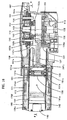
- FIG. 8 is a sectional view showing an entire electric hammer 101 according to this embodiment.
- FIG. 9 is an enlarged sectional view showing an essential part of the hammer.
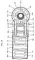
- FIG. 10 is a sectional view taken along line D-D in FIG. 9 .
- This embodiment is a modification to the mechanical vibration mechanism for forcibly vibrating the dynamic vibration reducer 171 in the electric hammer 101 having the dynamic vibration reducer 171 that reduces vibration of the body 103.
- forced vibration ofthe dynamic vibration reducer 171 is effected by the second crank mechanism which is mounted on a motion converting mechanism 213 that drives the striker 143, and the second motion converting mechanism 116 in the above-mentioned first embodiment is omitted.
- the second crank mechanism which is mounted on a motion converting mechanism 213 that drives the striker 143
- the second motion converting mechanism 116 in the above-mentioned first embodiment is omitted.
- it has the same construction as the first embodiment.
- Components or elements in this embodiment which are substantially identical to those in the first embodiment are given like numerals as in the first embodiment and will not be described or only briefly described.
- the motion converting mechanism 213 includes the first crank mechanism that drives the striker 143 and the second crank mechanism that drives the dynamic vibration reducer 171.
- the first crank mechanism mainly includes a driving gear 221 that is rotated in a horizontal plane by the driving motor 111 (see FIG.
- a driven gear 223 that engages with the driving gear 221
- a crank shaft 225 that rotates together with the driven gear 223
- a crank plate 225a that is integrally formed on the upper end of the crank shaft 225
- a connecting member in the form of a crank arm 227 that is loosely connected at its one end to the crank plate 225a via an eccentric pin 226 in a position displaced a predetermined distance from the center of rotation of the crank plate 225a
- a driving element in the form of a piston 229 mounted to the other end of the crank arm 227 via a connecting shaft 228.
- the second crank mechanism mainly includes an eccentric shaft portion 255 integrally formed with the crank shaft 225, a connecting plate 257 that is caused to reciprocate in the axial direction of the hammer bit 119 by rotation of the eccentric shaft portion 255, and an actuating member in the form of right and left straight rods 259 that linearly move together with the connecting plate 257 and move the slide sleeve 151 forward.
- the eccentric shaft portion 255 has a circular shape of which center is displaced a predetermined distance from the center of rotation of the crank shaft 225.
- the connecting plate 257 is engaged with a ring 255a that is fitted on the eccentric shaft portion 255, via an elliptical hole 257a elongated in a direction transverse to the axial direction of the hammer bit. Further, the connecting plate 257 is guided by front and rear guide pins 256 mounted to the gear housing 107 in such a manner as to linearly move. Further, front and rear guide grooves 257c are formed in the connecting plate 257 and extend in the axial direction of the hammer bit, and the guide grooves 257c are slidably engaged with the associated guide pins 256. As shown in FIG.
- the right and left rods 259 are slidably fitted into respective guide holes 107c that are formed through the cylinder holding portion 107a of the gear housing 107 in the axial direction of the hammer bit.
- One axial end (rear end) of each of the rods 259 is held in contact with a planar front surface 257b of the connecting plate 257, while the other axial end (front end) is held in contact with a rear end surface of the slide sleeve 151 of the dynamic vibration reducer 171.
- the opening 107b is formed in the gear housing 107 above the motion converting mechanism 213 and covered by a crank cap 263 which is removably fastened to the gear housing 107 by screws 263a.
- the weight 173 is actively driven via the biasing springs 175F, 175R by linearly moving the slide sleeve 151 via the second crank mechanism.
- vibration which is caused in the body 103 in the axial direction of the hammer bit during hammering operation can be effectively reduced or alleviated by forced vibration of the dynamic vibration reducer 171.
- the second crank mechanism that forcibly vibrates the dynamic vibration reducer 171 is mounted on the first crank mechanism that drives the striker 143.
- the eccentric shaft portion 255 is disposed on the crank shaft 225, and the slide sleeve 151 is driven via the connecting plate 257 that engages with the eccentric shaft portion 255 and via the rods 259.
- the number of parts for driving the slide sleeve 151 can be reduced compared with the first embodiment.
- the electric hammer 101 is described as a representative example of the impact tool.
- the present invention can also be applied to a hammer drill in which the hammer bit 119 can perform a striking movement in its axial direction and a rotation around its axis.
- FIG. 11 shows an entire electric hammer 101 as the impact tool not relating to the present invention.
- FIGS. 12 and 13 are enlarged sectional views each showing an essential part of the hammer, in the open state and the closed state of an air vent of an air chamber, respectively.
- FIG. 14 is a sectional view taken along line A-A in FIG. 12 .
- the hammer 101 of this impact tool includes a body 103, a hammer bit 119 detachably coupled to the tip end region (on the left side as viewed in FIG. 11 ) of the body 103 via a tool holder 137, and a handgrip 109 that is connected to the body 103 on the side opposite the hammer bit 119 and designed to be held by a user.
- the body 103 and the hammer bit 119 are features that correspond to the "tool body” and the "tool bit", respectively.
- the hammer bit 119 is held by the tool holder 137 such that it is allowed to reciprocate with respect to the tool holder 137 in its axial direction and prevented from rotating with respect to the tool holder 137 in its circumferential direction.
- the side of the hammer bit 119 is taken as the front side and the side of the handgrip 109 as the rear side.
- the body 103 includes a motor housing 105 that houses a driving motor 111, and a gear housing 107 that houses a first motion converting mechanism 113 and a second motion converting mechanism 116, and a barrel housing 108 that houses a striking mechanism 115.
- the rotating output of the driving motor 111 is appropriately converted into linear motion via the first motion converting mechanism 113 and transmitted to the striking element 115. Then, an impact force is generated in the axial direction of the hammer bit 119 via the striking element 115. Further, the rotating output of the driving motor 111 is transmitted to the second motion converting mechanism 116 via the first motion converting mechanism 113 and converted into linear motion by the second motion converting mechanism 116.
- the linear motion is inputted into a slide sleeve 151 that opens and closes an air vent 141b of an air chamber 141a which will be described below, as a driving force for sliding the slide sleeve 151.
- the driving motor 111 is a feature that corresponds to the "motor”.
- a slide switch 109a is provided on the handgrip 109 and can be slid by the user to drive the driving motor 111.
- the first motion converting mechanism 113 includes a driving gear 121 that is rotated in a horizontal plane by the driving motor 111 (see FIG. 11 ), a first crank shaft 125 integrally having a driven gear 123 that engages with the driving gear 121, a connecting member in the form of a crank arm 127 that is loosely connected at its one end to the first crank shaft 125 via an eccentric pin 126 in a position displaced a predetermined distance from the center of rotation of the first crank shaft 125, and a driving element in the form of a piston 129 mounted to the other end of the crank arm 127 via a connecting shaft 128.
- the first crank shaft 125, the eccentric pin 126, the crank arm 127 and the piston 129 form a first crank mechanism.
- the striking mechanism 115 includes a striking element in the form of a striker 143 that is slidably disposed within the bore of the cylinder 141, and an intermediate element in the form of an impact bolt 145 that is slidably disposed within the tool holder 137 and transmits the kinetic energy of the striker 143 to the hammer bit 119.
- An air chamber 141a is defined between the piston 129 and the striker 143 within the cylinder 141.
- the striker 143 is driven via the action of an air spring of the air chamber 141 of the cylinder 141 which is caused by sliding movement of the piston 129.
- the striker 143 then collides with (strikes) the intermediate element in the form of the impact bolt 145 that is slidably disposed within the tool holder 137 and transmits the striking force to the hammer bit 119 via the impact bolt 145.
- the cylinder 141 is disposed coaxially with the hammer bit 119. Therefore, the piston 129 and the striker 143 linearly move on the same axis as the hammer bit 119. Further, the cylinder 141 is inserted from the front into the bore of a cylindrical cylinder holding portion 107a formed in the front region of the gear housing 107 and held there, and is housed within the barrel housing 108 joined to the gear housing 107.
- the air chamber 141 serves to drive the striker 143 via the action of the air spring and communicates with the outside via one or more pressure regulating air vents 141 b that are formed in the cylinder 141 and radially extend through it.
- the air vent 141 b is a feature that corresponds to the "ventilation part”.
- a slide sleeve 151 is disposed outside the cylinder 141 and serves to open and close the air vent 141b.
- the slide sleeve 151 is a feature that corresponds to the "ventilation part opening-closing member".
- the slide sleeve 151 is fitted on the cylinder 141 such that it can slide in the axial direction of the hammer bit, and the slide sleeve 151 is slid by the second motion converting mechanism 116.
- the slide sleeve 151 has a ring-like groove 151b and a plurality of communication holes 151c.
- the ring-like groove 151b is formed in the inner wall surface of the slide sleeve 151, having a predetermined width in the axial direction and extending in the circumferential direction of the slide sleeve 151.
- the communication holes 151c radially extend through the slide sleeve 151 in such a manner as to provide communication between the groove 151b and the outside.
- the slide sleeve 151 slides on the cylinder 141 and is placed in a region in which the ring-like groove 151b faces the air vent 141b of the cylinder 141, the slide sleeve 151 opens the air vent 141b.
- the slide sleeve 151 moves out of the region in which the ring-like groove 151 b faces the air vent 141b, the slide sleeve 151 closes the air vent 141b.
- the second motion converting mechanism 116 is disposed above the first motion converting mechanism 113.
- the second motion converting mechanism 116 mainly includes a second crank shaft 153 that is rotationally driven in a horizontal plane by rotation of the eccentric pin 126 of the first motion converting mechanism 113, an eccentric shaft portion 155 integrally formed with the second crank shaft 153, a connecting member in the form of a connecting plate 157 that is caused to reciprocate in the axial direction of the hammer bit by rotation of the eccentric shaft portion 155, an actuating member in the form of right and left straight rods 159 that linearly move together with the connecting plate 157 and move the slide sleeve 151 forward, and a pressing spring 161 that biases the slide sleeve 151 in such a manner as to move the slide sleeve 151 rearward.
- the second crank shaft 153, the eccentric shaft portion 155 and the connecting plate 157 form the second crank mechanism which is a feature that corresponds to the "second crank mechanism
- the second crank shaft 153 is coaxially opposed to the first crank shaft 125.
- the second crank shaft 153 has a disk-like portion 153a on its axial lower end.
- a recess (groove) 153b is formed in the lower surface of the disk-like portion 153a in a position displaced from the center of rotation of the second crank shaft 153.
- the recess 153b is engaged with a protruding end 126a of the eccentric pin 126 of the first motion converting mechanism 113.
- the recess 153b and the protruding end 126a are features that correspond to the "concave portion" and the "convex portion", respectively.
- the second crank shaft 153 is rotationally driven by a driving force that is inputted from the first crank shaft 125 via engagement between the recess 153b and the protruding end 126.
- An opening 107b to be used for mounting the first motion converting mechanism 113 is formed in the gear housing 107 above the first motion converting mechanism 113.
- the second crank mechanism is mounted on a crank cap 163 which is removably fitted over the opening 107b.
- the crank cap 163 is a feature that corresponds to the "covering member".
- the second crank shaft 153 is rotatably supported on the crank cap 163 via a bearing 165.
- the eccentric shaft portion 155 has a circular shape of which center is displaced a predetermined distance from the center of rotation of the second crank shaft 153.
- the connecting plate 157 is engaged with a ring 155a that is fitted on the eccentric shaft portion 155, via an elliptical hole 157a elongated in a direction transverse to the axial direction of the hammer bit. Further, the connecting plate 157 is guided by front and rear guide pins 156 mounted to the crank cap 163 in such a manner as to linearly move in the axial direction of the hammer bit.
- front and rear guide grooves 157c are formed in the connecting plate 157 and extend in the axial direction of the hammer bit, and the guide grooves 157c are slidably engaged with the associated guide pins 156.
- the right and left rods 159 are slidably fitted into respective guide holes 107c that are formed through the cylinder holding portion 107a of the gear housing 107 in the axial direction of the hammer bit.
- One axial end (rear end) of each of the rods 159 is held in contact with a planar front surface 157b of the connecting plate 157, while the other axial end (front end) is held in contact with a rear end surface of the slide sleeve 151.
- the pressing spring 161 is a coil spring disposed outside the slide sleeve 151.
- One axial end (rear end) ofthe pressing spring 161 is held in contact with a flange 151 a of the slide sleeve 151, while the other axial end (front end) is held in contact with a stepped surface 108a ofthe barrel housing 108.
- the second crank shaft 153 and the connecting plate 157 which form the second crank mechanism are mounted to the crank cap 163 before the crank cap 163 is mounted on the opening 107b of the gear housing 107.
- the connecting plate 157 is held between the inner wall surface of the crank cap 163 and the disk-like portion 153a of the second crank shaft 153, so that the connecting plate 157 is prevented from moving in the axial direction of the second crank shaft 153.
- the crank cap 163 with the second crank shaft 153 and the connecting plate 157 mounted thereto is fitted over the opening 107b from outside (above) the gear housing 107 and fastened to the gear housing 107 by a plurality of screws 163a.
- the recess 153b formed in the disk-like portion 153a of the second crank shaft 153 is engaged with the protruding end 126a of the eccentric pin 126 of the first crank mechanism which is already mounted within the gear housing 107, and the rear end of the rod 159 is brought into contact with the front surface 157b of the connecting plate 157.
- the first and second crank mechanisms are assembled in a mechanically interconnected manner such that the rotating force can be transmitted.
- the kinetic energy of the striker 143 which is caused by the collision with the impact bolt 145 is transmitted to the hammer bit 119.
- the hammer bit 119 performs a striking movement in its axial direction, and the hammering operation is performed on the workpiece.
- the slide sleeve 151 controls opening and closing of the air vent 141b of the cylinder 141 via the second motion converting mechanism 116.
- the eccentric shaft portion 155 of the second crank shaft 153 is caused to rotate in a horizontal plane.
- the connecting plate 157 engaged with the eccentric shaft portion 155 is caused to reciprocate in the axial direction of the hammer bit 119.
- the maximum retracted end or the rearmost position to which the piston 129 can be moved is defined as the top dead center, while the maximum advanced end or the front position to which the piston 129 can be moved is defined as the bottom dead center.
- the crank angle of the first crank mechanism is 0°, the piston 129 is placed in the top dead center, while, when the crank angle is 180°, the piston 129 is placed in the bottom dead center.
- the opening and closing timing of the slide sleeve 151 is set such that, when the crank angle is in the range of about 135° to 220°, the air vent 141b of the air chamber 141a is opened, while, otherwise or when the crank angle is in the range of about 0° to 135° or 220° to 360°, the air vent 141 b is closed.
- FIG. 12 shows the state in which the air vent 141b is open and
- FIG. 13 shows the state in which the air vent 141b is closed.
- the air chamber 141a has a minimum capacity when the piston 129 is moved a crank angle of about 70° to 87° from the top dead center. Specifically, the piston 129 is placed closest to the striker 143 so that air within the air chamber 141a is compressed to a maximum extent. Thereafter, the striker 143 is caused to move forward by pressure ofthe high-pressure compressed air. When the crank angle is about 180°, the striker 143 strikes the hammer bit 119 via the impact bolt 145. After the striking movement, the striker 143 is caused to move rearward by rebound of the striking movement and by pressure difference (suction force) between the pressure within the air chamber 141 a which acts upon the rear end surface of the striker 143 and the outside pressure (substantially the atmospheric pressure).
- the period between the instant when the striker 143 starts moving forward and the instant when the striker 143 returns to the initial position after colliding with the hammer bit 119 is defined as one cycle.
- the slide sleeve 151 starts opening the air vent 141b at the crank angle of about 137° and then holds the open state in a predetermined angle range. Thereafter, the slide sleeve 151 closes the air vent 141b at the crank angle of about 220°.
- the times when the slide sleeve 151 opens and closes the air vent 141b can be arbitrarily set in the relationship with the position of the striker 143 (the piston 129).
- such times can be set such that, during forward movement (striking movement) of the striker 143, the air vent 141 b is opened in the position where (at the time when) high-pressure pressurized air within the air chamber 141a can provide optimum striking speed for the striker 143. Further, during rearward movement of the striker 143, the air vent 141b is closed in the position where (at the time when) the striker 143 can be acted upon by optimum suction force. As a result, performance of the electric hammer 101 can be improved. Further, the period (interval) during which the air vent 141b is open is determined by the width (in the axial direction of the hammer bit 119) of the ring-like groove 151b formed in the slide sleeve 151.
- the times when the slide sleeve 151 opens and closes the air vent 141b can be easily adjusted by appropriately adjusting (setting) the position of the eccentric shaft portion 155 of the second crank mechanism in the direction of rotation with respect to the eccentric pin 126 of the first crank mechanism which drives the striker 143.
- the period during which the air vent 141 b is open can be appropriately adjusted by changing the width of the ring-like groove 151b formed in the slide sleeve 151.
- the air vent 141b can be opened only when necessary and only during a necessary period.
- both the striker 143 and the slide sleeve 151 can be efficiently driven by the single driving motor 111.
- the crank cap 163 is fitted over the opening 107b in order to close the opening 107b of the gear housing 107, and the second crank shaft 153 and the connecting plate 157 which form the second crank mechanism are mounted on the crank cap 163. Moreover, when the crank cap 163 is fitted over the opening 107b, the recess 153b formed in the disk-like portion 153a of the second crank shaft 153 is engaged with the protruding end 126a of the eccentric pin 126 of the first crank shaft 125, so that the second crank mechanism is mechanically interconnected with the first crank mechanism. With this construction, the second crank mechanism can be mounted simply by mounting the crank cap 163 on the opening 107b. Thus, according to this embodiment, mounting of the second crank mechanism is facilitated and ease of assembly can be increased.
- the opening 107b formed in the gear housing 107 is designed and provided as a hole through which the first crank mechanism is mounted in the gear housing 107. Further, an upper region above the first crank mechanism exists as free space. In this impact tool, the second crank mechanism is disposed by utilising this free space, so that the second crank mechanism can be installed without changing the outside dimensions of the existing electric hammer 101.
- FIG. 15 shows an entire electric hammer 101 according to this embodiment.
- FIG. 16 is an enlarged sectional view showing an essential part of the hammer.
- FIG. 17 is a sectional view taken along line B-B in FIG. 16 .
- a dynamic vibration reducer 171 for reducing vibration of the body 103 is installed in the hammer 101.
- the slide sleeve 151 that linearly moves in the axial direction of the hammer bit in order to open and close the air vent 141b of the air chamber 141a is utilized as a vibration means for actively vibrating the dynamic vibration reducer 171.
- it has the same construction as the first embodiment.
- Components or elements in this embodiment which are substantially identical to those in the first embodiment are given like numerals as in the first embodiment and will not be described or only briefly described.
- forcibly vibrating the dynamic vibration reducer 171 is referred to as forced vibration.
- the dynamic vibration reducer 171 is provided in the inner space of the barrel housing 108 and mainly includes a cylindrical weight 173 annularly arranged outside the cylinder 141 and front and rear biasing springs 175F, 175R disposed on the front and rear sides of the weight 173 in the axial direction of the hammer bit.
- the front and rear biasing springs 175F, 175R exert a spring force on the weight 173 in a direction toward each other when the weight 173 moves in the axial direction of the hammer bit 119.
- the weight 173 is arranged such that its center (of gravity) coincides with the axis ofthe hammer bit 119 and can freely slide with its outer wall surface held in contact with the inner wall surface of the barrel housing 108.
- the front and rear biasing springs 175F, 175R are formed by compression coil springs and, like the weight 173, they are arranged such that each of their centers coincides with the axis of the hammer bit 119.
- One end (rear end) of the rear biasing spring 175R is held in contact with a front surface of the flange 151a of the slide sleeve 151, while the other end (front end) is held in contact with the axial rear end of the weight 173.
- the rear biasing spring 175R also serves as a pressing spring for biasing the slide sleeve 151 rearward.
- the dynamic vibration reducer 171 having the above-described construction serves to reduce impulsive and cyclic vibration caused during hammering operation (when the hammer bit 119 is driven).
- the weight 173 and the biasing springs 175F, 175R serve as vibration reducing elements in the dynamic vibration reducer 171 and cooperate to passively reduce vibration of the body 103 of the hammer 101.
- the vibration of the body 103 in the hammer 101 can be effectively alleviated or reduced.
- the connecting plate 157 engaged with the eccentric shaft portion 155 is caused to reciprocate in the axial direction of the hammer bit 119.
- the connecting plate 157 moves forward, the slide sleeve 151 is pushed forward via the rod 159 and compresses the biasing springs 175F, 175R.
- the connecting plate 157 moves rearward, the slide sleeve 151 is pushed rearward by the spring force of the biasing springs 175F, 175R.
- the weight 173 of the dynamic vibration reducer 171 is actively driven via the biasing springs 175F, 175R and causes the dynamic vibration reducer 171 to be forcibly vibrated.
- the slide sleeve 151 serves as a vibration means for forcibly vibrating the dynamic vibration reducer 171 by actively driving the weight 173 of the dynamic vibration reducer 171.
- the dynamic vibration reducer 171 serves as an active vibration reducing mechanism in which the weight 173 is actively driven. Therefore, the vibration which is caused in the body 103 during hammering operation can be further effectively reduced or alleviated.
- the slide sleeve 151 can provide forced vibration of the dynamic vibration reducer 171 while maintaining the function of controlling opening and closing ofthe air vents 141b which is described in the first embodiment.
- the weight 173 and the biasing springs 175F, 175R which form the dynamic vibration reducer 171 are annularly arranged outside the cylinder 141.
- the outer peripheral space of the cylinder 141 can be effectively utilized.
- the weight 173 and the biasing springs 175F, 175R can be disposed such that their centers of gravity are placed on the axis of the hammer bit 119.
- a couple force of lateral or vertical rotation around an axis extending transverse to the axial direction of the hammer bit
- the weight 173 is disposed such that it can slide in the axial direction of the hammer bit along the inner wall surface of the barrel housing 108. With this construction, the sliding movement of the weight 173 can be stabilized.
- the electric hammer 101 is described as a representative example of the impact tool.
- the present invention can also be applied to a hammer drill in which the hammer bit 119 can perform a striking movement in its axial direction and a rotation around its axis.
Landscapes
- Engineering & Computer Science (AREA)
- Mechanical Engineering (AREA)
- Percussive Tools And Related Accessories (AREA)
Claims (11)
- Outil d'impact adapté pour avoir une mèche d'outil (119) couplée de manière détachable à celui-ci, lequel outil d'impact réalise une opération de martelage prédéterminée sur une pièce de travail par un mouvement de frappe de la mèche d'outil (119) dans sa direction axiale, comprenant :un corps d'outil (103),un cylindre (141) logé dans le corps d'outil (103),un réducteur de vibration dynamique (171) présentant un poids (173) qui se déplace linéairement sous une force d'inclinaison d'un élément élastique (175F, 175R), dans lequel le réducteur de vibration dynamique (171) réduit la vibration du corps d'outil (103) pendant l'opération de martelage par le mouvement du poids (173) dans la direction axiale de la mèche d'outil (119) etun mécanisme de vibration mécanique qui entraîne activement le poids (173) par application d'une force externe autre que la vibration du corps d'outil (103) au poids (173) via l'élément élastique (175F, 175R), dans lequelle poids (173) et l'élément élastique (175F, 175R) sont agencés sur l'axe de la mèche d'outil (119) et entre une surface de paroi intérieure du corps d'outil (103) et une surface de paroi extérieure du cylindre (141) de manière à couvrir au moins une partie de la surface de paroi extérieure du cylindre (141) dans la direction circonférentielle,l'élément élastique (175F, 175R) est agencé respectivement sur des côtés avant et arrière du poids (173) etle mécanisme de vibration mécanique comporte un élément coulissant (151) qui se déplace linéairement dans la direction axiale de la mèche d'outil (119) de manière à appliquer une force externe à l'élément élastique (175F, 175R),caractérisé en ce que l'élément coulissant (151) compresse l'élément élastique lorsque l'élément coulissant (151) est déplacé vers une position d'extrémité avant et l'élément coulissant (151) est poussé vers une position d'extrémité arrière par la force d'inclinaison de l'élément élastique (175F, 175R).
- Outil d'impact selon la revendication 1, comprenant en outre un mécanisme d'actionnement qui entraîne linéairement la mèche d'outil (119), dans lequel :le mécanisme d'actionnement comporte un moteur (111), un élément de frappe (143) qui se déplace linéairement dans la direction axiale de la mèche d'outil (119) de manière à provoquer le déplacement linéaire de la mèche d'outil (119), et un premier mécanisme à vilebrequin (125, 126, 127, 129 ; 225, 226, 227, 229) qui convertit une sortie rotative du moteur en mouvement linéaire et entraîne par là-même l'élément de frappe (143) etle mécanisme de vibration mécanique comporte en outre un second mécanisme à vilebrequin (153, 155, 157; 225, 255, 257) qui convertit la rotation du premier mécanisme à vilebrequin (125, 126, 127, 129 ; 225, 226, 227, 229) en mouvement linéaire et entraîne par là-même l'éliment coulissant (151).
- Outil d'impact selon la revendication 2, comprenant en outre :une ouverture (107b) qui est formée dans le corps d'outil (103) et prévue sous forme de trou, par lequel le premier mécanisme à vilebrequin (125, 126, 127, 129) est monté dans le corps d'outil (103), etun élément de couverture (163) qui peut être monté sur l'ouverture (107b) de l'extérieur du corps d'outil (103) de manière à fermer l'ouverture (107b), dans lequel :le premier mécanisme à vilebrequin (125, 126, 127, 129) possède un vilebrequin (125) qui est agencé de manière rotative dans le corps d'outil (103) et fait face à l'ouverture (107b),le second mécanisme à vilebrequin (153, 155, 157) possède un vilebrequin (153) qui est monté de manière rotative sur l'élément de couverture (163) et opposé au vilebrequin (125) du premier mécanisme à vilebrequin (125, 126, 127, 129),une partie concave (153b) est formée dans l'une des extrémités opposées des vilebrequins (125, 153) des premier et second mécanismes à vilebrequin et une partie convexe (126a) est formée sur l'autre des extrémités opposées des vilebrequins (125, 153) et peut s'engager avec la partie concave (153b) etlorsque l'élément de couverture (163) est monté sur l'ouverture (107b), le vilebrequin (125) du premier mécanisme à vilebrequin (125, 126, 127, 129) et le vilebrequin (153) du second mécanisme à vilebrequin (153, 155, 157) sont reliés ensemble par engagement entre la partie concave (153b) et la partie convexe (126a) de sorte que la rotation du vilebrequin (125) du premier mécanisme à vilebrequin (125, 126, 127, 129) puisse être transmise au vilebrequin (153) du second mécanisme à vilebrequin (153, 155, 157).
- Outil d'impact selon la revendication 2, dans lequel le premier mécanisme à vilebrequin (225, 226, 227, 229) comporte un vilebrequin rotatif (225) présentant une partie excentrique (226) dans une position déplacée de son centre de rotation, et un élément de liaison (227) qui convertit la rotation de la partie excentrique (226) en mouvement linéaire de l'élément d'entraînement (229) et
le second mécanisme à vilebrequin (225, 255, 257) comporte un vilebrequin rotatif (225) présentant une partie excentrique (255) dans une position déplacée de son centre de rotation, et un élément de liaison (257) qui convertit la rotation de la partie excentrique (255) en mouvement linéaire de l'élément coulissant (151). - Outil d'impact selon l'une quelconque des revendications 1 à 4, dans lequel le poids (173) est agencé sur le corps d'outil (103) de sorte que le poids (173) puisse se déplacer le long de la surface de paroi intérieure du corps d'outil (103) dans la direction axiale de la mèche d'outil (119).
- Outil d'impact selon la revendication 1, comprenant en outre :un élément d'entraînement (129 ; 229) qui se déplace linéairement dans la direction axiale de la mèche d'outil (119) dans le cylindre (141),un élément de frappe (143) qui se déplace linéairement dans la direction axiale de la mèche d'outil (119) dans le cylindre (141),une chambre à air (141 a) définie entre l'élément d'entraînement (129 ; 229) et l'élément de frappe (143) dans le cylindre (141), dans lequel l'élément de frappe (143) est amené à se déplacer linéairement via des fluctuations de pression de la chambre à air (141a) suite au mouvement linéaire de l'élément d'entraînement (129 ; 229) et frappe la mèche d'outil (119), moyennant quoi l'opération de martelage prédéterminée est réalisée sur la pièce de travail,une partie de ventilation (141 b) qui est formée dans le cylindre (141) et fournit la communication entre la chambre à air (141a) et le côté extérieur afin de réguler la pression de la chambre à air (141a) de sorte à atteindre le mouvement doux de l'élément de frappe (143) etun élément de fermeture et d'ouverture de partie de ventilation (151) qui est agencé en dehors du cylindre (141) et peut coulisser dans la direction axiale de la mèche d'outil (119), dans lequel pendant l'opération de martelage par la mèche d'outil (119), l'élément de fermeture et d'ouverture de partie de ventilation (151) commande l'ouverture et la fermeture de la partie de ventilation (141b) par le déplacement entre une position ouverte pour l'ouverture de la partie de ventilation (141 b) et une position fermée pour la fermeture de la partie de ventilation (141b) à un minutage prédéterminé.
- Outil d'impact selon la revendication 6, comprenant en outre un moteur (111) logé dans le corps d'outil (103), un premier mécanisme à vilebrequin (125, 126, 127, 129; 225, 226, 227, 229) qui convertit une sortie rotative du moteur en mouvement linéaire dans la direction axiale de la mèche d'outil (119) et entraîne par là-même l'élément d'entraînement (129 ; 229), et un second mécanisme à vilebrequin (153, 155, 157 ; 225, 255, 257) qui convertit la rotation du premier mécanisme à vilebrequin (125, 126, 127, 129; 225, 226, 227, 229) en mouvement linéaire dans la direction axiale de la mèche d'outil (119) et entraîne par là-même l'élément de fermeture et d'ouverture de partie de ventilation (151).
- Outil d'impact selon la revendication 7, comprenant en outre :une ouverture (107b) qui est formée dans le corps d'outil (103) et prévue sous forme de trou, par lequel le premier mécanisme à vilebrequin (125, 126, 127, 129) est monté dans le corps d'outil (103) etun élément de couverture (163) qui peut être monté sur l'ouverture (107b) de l'extérieur du corps d'outil (103) de manière à fermer l'ouverture (107b), dans lequel :le premier mécanisme à vilebrequin (125, 126, 127, 129) possède un vilebrequin (125) qui est agencé de manière rotative dans le corps d'outil (103) et fait face à l'ouverture,le second mécanisme à vilebrequin (153, 155, 157) possède un vilebrequin (153) qui est monté de manière rotative à l'élément de couverture (163) et opposé au vilebrequin (125) du premier mécanisme à vilebrequin (125, 126, 127, 129),une partie concave (153b) est formée dans l'une des extrémités opposées des vilebrequins (125, 153) des premier et second mécanismes à vilebrequin, et une partie convexe (126a) est formée sur l'autre des extrémités opposées des vilebrequins (125, 153) et peut s'engager avec la partie concave (153b) etlorsque l'élément de couverture (163) est monté sur l'ouverture (107b), le vilebrequin (125) du premier mécanisme à vilebrequin (125, 126, 127, 129) et le vilebrequin (153) du second mécanisme à vilebrequin (153, 155, 157) sont reliés ensemble par engagement entre la partie concave (153b) et la partie convexe (126a) de sorte que la rotation du vilebrequin (125) du premier mécanisme à vilebrequin (125, 126, 127, 129) puisse être transmise au vilebrequin (153) du second mécanisme à vilebrequin (153, 155, 157).
- Outil d'impact selon la revendication 7, dans lequel :le premier mécanisme à vilebrequin (225, 226, 227, 229) comporte un vilebrequin rotatif (225) présentant une partie excentrique (226) dans une position déplacée de son centre de rotation, et un élément de liaison (227) qui convertit la rotation de la partie excentrique (226) en mouvement linéaire de l'élément d'entraînement (229) etle second mécanisme à vilebrequin (225, 255, 257) comporte un vilebrequin rotatif (225) présentant une partie excentrique (255) dans une position déplacée de son centre de rotation, et un élément de liaison (257) qui convertit la rotation de la partie excentrique (255) en mouvement linéaire de l'élément de fermeture et d'ouverture de partie de ventilation (151).
- Outil d'impact selon l'une quelconque des revendications 7 à 9, dans lequel si une position d'extrémité arrière rétractée maximale et une position d'extrémité avant avancée maximale de l'élément d'entraînement (129 ; 229) sont prises à 0 et 180° respectivement en termes d'angle de vilebrequin du premier mécanisme à vilebrequin (125, 126, 127, 129; 225, 226, 227, 229), l'élément de fermeture et d'ouverture de partie de ventilation (151) ouvre la partie de ventilation (141 b) lorsque l'angle de vilebrequin est dans la plage d'environ 135 à 220° et ferme la partie de ventilation (141b) en dehors de ladite plage d'angle.
- Outil d'impact selon l'une quelconque des revendications 6 à 10,
dans lequel l'élément de fermeture et d'ouverture de partie de ventilation (151) sert de moyen de vibration pour faire vibrer à force le réducteur de vibration dynamique (171) par entraînement actif du poids (173) via l'élément élastique (175F, 175R).
Applications Claiming Priority (2)
| Application Number | Priority Date | Filing Date | Title |
|---|---|---|---|
| JP2007159152A JP5009059B2 (ja) | 2007-06-15 | 2007-06-15 | 打撃工具 |
| JP2007159166A JP5009060B2 (ja) | 2007-06-15 | 2007-06-15 | 打撃工具 |
Publications (3)
| Publication Number | Publication Date |
|---|---|
| EP2002938A2 EP2002938A2 (fr) | 2008-12-17 |
| EP2002938A3 EP2002938A3 (fr) | 2010-07-07 |
| EP2002938B1 true EP2002938B1 (fr) | 2016-07-06 |
Family
ID=39730728
Family Applications (1)
| Application Number | Title | Priority Date | Filing Date |
|---|---|---|---|
| EP08010832.7A Active EP2002938B1 (fr) | 2007-06-15 | 2008-06-13 | Outil d'impact avec réducteur de vibrations |
Country Status (3)
| Country | Link |
|---|---|
| US (1) | US7832498B2 (fr) |
| EP (1) | EP2002938B1 (fr) |
| RU (1) | RU2478034C2 (fr) |
Families Citing this family (15)
| Publication number | Priority date | Publication date | Assignee | Title |
|---|---|---|---|---|
| US7806201B2 (en) * | 2007-07-24 | 2010-10-05 | Makita Corporation | Power tool with dynamic vibration damping |
| JP5361504B2 (ja) * | 2009-04-10 | 2013-12-04 | 株式会社マキタ | 打撃工具 |
| JP5345893B2 (ja) | 2009-05-08 | 2013-11-20 | 株式会社マキタ | 打撃工具 |
| DE102009027422A1 (de) * | 2009-07-02 | 2011-01-05 | Robert Bosch Gmbh | Vorrichtung zur Reduktion und/oder Kompensation von Vibrationen, insbesondere für eine Handwerkzeugmaschine und zur Verwendung in Handwerkzeugmaschinen |
| DE102009054723A1 (de) * | 2009-12-16 | 2011-06-22 | Robert Bosch GmbH, 70469 | Handwerkzeugmaschine |
| JP5767511B2 (ja) * | 2011-06-01 | 2015-08-19 | 株式会社マキタ | 往復動式作業工具 |
| DE102011081617A1 (de) * | 2011-08-26 | 2013-02-28 | Hilti Aktiengesellschaft | Handgehaltene Werkzeugmaschine |
| DE102012208986A1 (de) * | 2012-05-29 | 2013-12-05 | Hilti Aktiengesellschaft | Meißelnde Werkzeugmaschine |
| JP6510250B2 (ja) * | 2015-01-29 | 2019-05-08 | 株式会社マキタ | 作業工具 |
| CN106737423B (zh) * | 2016-12-26 | 2023-11-10 | 新沂市宏祥电子有限公司 | 安全射钉器 |
| US10814468B2 (en) | 2017-10-20 | 2020-10-27 | Milwaukee Electric Tool Corporation | Percussion tool |
| CN214723936U (zh) | 2018-01-26 | 2021-11-16 | 米沃奇电动工具公司 | 冲击工具 |
| US11571796B2 (en) | 2018-04-04 | 2023-02-07 | Milwaukee Electric Tool Corporation | Rotary hammer |
| EP3670097A1 (fr) * | 2018-12-21 | 2020-06-24 | Hilti Aktiengesellschaft | Machine-outil portative |
| CN115056362B (zh) * | 2022-07-05 | 2022-12-13 | 永康市灵威电器有限公司 | 电动工具附件及锂电电动工具 |
Family Cites Families (19)
| Publication number | Priority date | Publication date | Assignee | Title |
|---|---|---|---|---|
| SU44889A1 (ru) * | 1934-11-27 | 1935-11-30 | И.М. Млодик | Электрический бурильный уголок |
| US2875731A (en) * | 1956-03-23 | 1959-03-03 | Buckeye Steel Castings Co | Vibration absorbers for reciprocating tools |
| US4279091A (en) * | 1979-12-03 | 1981-07-21 | Edwards Jesse B | Firearm recoil reducer |
| DE3122979A1 (de) * | 1981-06-10 | 1983-01-05 | Hilti AG, 9494 Schaan | Bohr- oder meisselhammer |
| GB9407902D0 (en) * | 1994-04-21 | 1994-06-15 | Univ Aberdeen | Moling apparatus |
| DE4415348A1 (de) * | 1994-05-02 | 1995-11-09 | Hilti Ag | Bohr- und Meisselgerät |
| JP3459493B2 (ja) * | 1995-05-25 | 2003-10-20 | 株式会社マキタ | 打撃工具 |
| IT1312111B1 (it) | 1999-05-18 | 2002-04-04 | Lamberti Spa | Miscele tensioattive atte all'uso come bagnanti ed emulsionati incomposizioni agrochimiche |
| GB0109747D0 (en) | 2001-04-20 | 2001-06-13 | Black & Decker Inc | Hammer |
| JP4270887B2 (ja) | 2003-01-10 | 2009-06-03 | 株式会社マキタ | 電動往復動式工具 |
| DE602004027011D1 (en) | 2003-03-21 | 2010-06-17 | Black & Decker Inc | Uziervorrichtung |
| DE602004026134D1 (de) * | 2003-04-01 | 2010-05-06 | Makita Corp | Kraftwerkzeug |
| US7604071B2 (en) * | 2004-04-30 | 2009-10-20 | Makita Corporation | Power tool with vibration reducing means |
| JP4527468B2 (ja) | 2004-08-17 | 2010-08-18 | 株式会社マキタ | 電動工具 |
| GB2429675A (en) * | 2005-06-23 | 2007-03-07 | Black & Decker Inc | Vibration dampening mechanism |
| JP4509890B2 (ja) | 2005-08-19 | 2010-07-21 | 株式会社マキタ | 衝撃式作業工具 |
| US7383895B2 (en) | 2005-08-19 | 2008-06-10 | Makita Corporation | Impact power tool |
| JP4686372B2 (ja) * | 2006-02-01 | 2011-05-25 | 株式会社マキタ | 衝撃式作業工具 |
| GB0804967D0 (en) * | 2008-03-18 | 2008-04-16 | Black & Decker Inc | Powered hammer with a vibration dampening mechanism |
-
2008
- 2008-06-11 US US12/155,902 patent/US7832498B2/en active Active
- 2008-06-13 EP EP08010832.7A patent/EP2002938B1/fr active Active
- 2008-06-16 RU RU2008124131/02A patent/RU2478034C2/ru active
Also Published As
| Publication number | Publication date |
|---|---|
| RU2478034C2 (ru) | 2013-03-27 |
| US7832498B2 (en) | 2010-11-16 |
| EP2002938A3 (fr) | 2010-07-07 |
| US20080308287A1 (en) | 2008-12-18 |
| RU2008124131A (ru) | 2009-12-27 |
| EP2002938A2 (fr) | 2008-12-17 |
Similar Documents
| Publication | Publication Date | Title |
|---|---|---|
| EP2002938A2 (fr) | Outil d'impact avec réducteur de vibrations | |
| EP1992453B1 (fr) | Outil d'impact | |
| EP2018939B1 (fr) | Outil électrique avec amortisseur de vibration | |
| EP1779979B1 (fr) | Outil de travail | |
| US7383895B2 (en) | Impact power tool | |
| RU2268818C2 (ru) | Механизированный инструмент | |
| EP1475190B1 (fr) | Outil électrique | |
| EP2564986B1 (fr) | Outil d'impact | |
| EP1439038B1 (fr) | Marteau électrique | |
| EP1992452B1 (fr) | Outil d'impact | |
| EP2159008B1 (fr) | Outil d'impact | |
| US9044848B2 (en) | Impact tool having a vibration reducing member | |
| EP2415565B1 (fr) | Machine-outil | |
| EP2529892B1 (fr) | Outil motorisé | |
| JP5009059B2 (ja) | 打撃工具 | |
| JP5009060B2 (ja) | 打撃工具 | |
| JP2004330377A (ja) | 作業工具 |
Legal Events
| Date | Code | Title | Description |
|---|---|---|---|
| PUAI | Public reference made under article 153(3) epc to a published international application that has entered the european phase |
Free format text: ORIGINAL CODE: 0009012 |
|
| AK | Designated contracting states |
Kind code of ref document: A2 Designated state(s): AT BE BG CH CY CZ DE DK EE ES FI FR GB GR HR HU IE IS IT LI LT LU LV MC MT NL NO PL PT RO SE SI SK TR |
|
| AX | Request for extension of the european patent |
Extension state: AL BA MK RS |
|
| RIC1 | Information provided on ipc code assigned before grant |
Ipc: B25D 17/24 20060101AFI20080911BHEP Ipc: B25D 17/06 20060101ALI20100316BHEP Ipc: B25D 11/12 20060101ALI20100316BHEP |
|
| PUAL | Search report despatched |
Free format text: ORIGINAL CODE: 0009013 |
|
| AK | Designated contracting states |
Kind code of ref document: A3 Designated state(s): AT BE BG CH CY CZ DE DK EE ES FI FR GB GR HR HU IE IS IT LI LT LU LV MC MT NL NO PL PT RO SE SI SK TR |
|
| AX | Request for extension of the european patent |
Extension state: AL BA MK RS |
|
| 17P | Request for examination filed |
Effective date: 20101105 |
|
| AKX | Designation fees paid |
Designated state(s): AT BE BG CH CY CZ DE DK EE ES FI FR GB GR HR HU IE IS IT LI LT LU LV MC MT NL NO PL PT RO SE SI SK TR |
|
| 17Q | First examination report despatched |
Effective date: 20130328 |
|
| GRAP | Despatch of communication of intention to grant a patent |
Free format text: ORIGINAL CODE: EPIDOSNIGR1 |
|
| INTG | Intention to grant announced |
Effective date: 20160215 |
|
| GRAS | Grant fee paid |
Free format text: ORIGINAL CODE: EPIDOSNIGR3 |
|
| GRAA | (expected) grant |
Free format text: ORIGINAL CODE: 0009210 |
|
| AK | Designated contracting states |
Kind code of ref document: B1 Designated state(s): AT BE BG CH CY CZ DE DK EE ES FI FR GB GR HR HU IE IS IT LI LT LU LV MC MT NL NO PL PT RO SE SI SK TR |
|
| REG | Reference to a national code |
Ref country code: GB Ref legal event code: FG4D |
|
| REG | Reference to a national code |
Ref country code: AT Ref legal event code: REF Ref document number: 810369 Country of ref document: AT Kind code of ref document: T Effective date: 20160715 Ref country code: CH Ref legal event code: EP |
|
| REG | Reference to a national code |
Ref country code: IE Ref legal event code: FG4D |
|
| REG | Reference to a national code |
Ref country code: DE Ref legal event code: R096 Ref document number: 602008044960 Country of ref document: DE |
|
| REG | Reference to a national code |
Ref country code: NL Ref legal event code: MP Effective date: 20160706 |
|
| REG | Reference to a national code |
Ref country code: LT Ref legal event code: MG4D |
|
| REG | Reference to a national code |
Ref country code: AT Ref legal event code: MK05 Ref document number: 810369 Country of ref document: AT Kind code of ref document: T Effective date: 20160706 |
|
| PG25 | Lapsed in a contracting state [announced via postgrant information from national office to epo] |
Ref country code: NL Free format text: LAPSE BECAUSE OF FAILURE TO SUBMIT A TRANSLATION OF THE DESCRIPTION OR TO PAY THE FEE WITHIN THE PRESCRIBED TIME-LIMIT Effective date: 20160706 Ref country code: LT Free format text: LAPSE BECAUSE OF FAILURE TO SUBMIT A TRANSLATION OF THE DESCRIPTION OR TO PAY THE FEE WITHIN THE PRESCRIBED TIME-LIMIT Effective date: 20160706 Ref country code: HR Free format text: LAPSE BECAUSE OF FAILURE TO SUBMIT A TRANSLATION OF THE DESCRIPTION OR TO PAY THE FEE WITHIN THE PRESCRIBED TIME-LIMIT Effective date: 20160706 Ref country code: IS Free format text: LAPSE BECAUSE OF FAILURE TO SUBMIT A TRANSLATION OF THE DESCRIPTION OR TO PAY THE FEE WITHIN THE PRESCRIBED TIME-LIMIT Effective date: 20161106 Ref country code: NO Free format text: LAPSE BECAUSE OF FAILURE TO SUBMIT A TRANSLATION OF THE DESCRIPTION OR TO PAY THE FEE WITHIN THE PRESCRIBED TIME-LIMIT Effective date: 20161006 Ref country code: FI Free format text: LAPSE BECAUSE OF FAILURE TO SUBMIT A TRANSLATION OF THE DESCRIPTION OR TO PAY THE FEE WITHIN THE PRESCRIBED TIME-LIMIT Effective date: 20160706 Ref country code: IT Free format text: LAPSE BECAUSE OF FAILURE TO SUBMIT A TRANSLATION OF THE DESCRIPTION OR TO PAY THE FEE WITHIN THE PRESCRIBED TIME-LIMIT Effective date: 20160706 |
|
| PG25 | Lapsed in a contracting state [announced via postgrant information from national office to epo] |
Ref country code: SE Free format text: LAPSE BECAUSE OF FAILURE TO SUBMIT A TRANSLATION OF THE DESCRIPTION OR TO PAY THE FEE WITHIN THE PRESCRIBED TIME-LIMIT Effective date: 20160706 Ref country code: LV Free format text: LAPSE BECAUSE OF FAILURE TO SUBMIT A TRANSLATION OF THE DESCRIPTION OR TO PAY THE FEE WITHIN THE PRESCRIBED TIME-LIMIT Effective date: 20160706 Ref country code: ES Free format text: LAPSE BECAUSE OF FAILURE TO SUBMIT A TRANSLATION OF THE DESCRIPTION OR TO PAY THE FEE WITHIN THE PRESCRIBED TIME-LIMIT Effective date: 20160706 Ref country code: AT Free format text: LAPSE BECAUSE OF FAILURE TO SUBMIT A TRANSLATION OF THE DESCRIPTION OR TO PAY THE FEE WITHIN THE PRESCRIBED TIME-LIMIT Effective date: 20160706 Ref country code: PT Free format text: LAPSE BECAUSE OF FAILURE TO SUBMIT A TRANSLATION OF THE DESCRIPTION OR TO PAY THE FEE WITHIN THE PRESCRIBED TIME-LIMIT Effective date: 20161107 Ref country code: PL Free format text: LAPSE BECAUSE OF FAILURE TO SUBMIT A TRANSLATION OF THE DESCRIPTION OR TO PAY THE FEE WITHIN THE PRESCRIBED TIME-LIMIT Effective date: 20160706 Ref country code: BE Free format text: LAPSE BECAUSE OF FAILURE TO SUBMIT A TRANSLATION OF THE DESCRIPTION OR TO PAY THE FEE WITHIN THE PRESCRIBED TIME-LIMIT Effective date: 20160706 Ref country code: GR Free format text: LAPSE BECAUSE OF FAILURE TO SUBMIT A TRANSLATION OF THE DESCRIPTION OR TO PAY THE FEE WITHIN THE PRESCRIBED TIME-LIMIT Effective date: 20161007 |
|
| REG | Reference to a national code |
Ref country code: DE Ref legal event code: R097 Ref document number: 602008044960 Country of ref document: DE |
|
| PG25 | Lapsed in a contracting state [announced via postgrant information from national office to epo] |
Ref country code: RO Free format text: LAPSE BECAUSE OF FAILURE TO SUBMIT A TRANSLATION OF THE DESCRIPTION OR TO PAY THE FEE WITHIN THE PRESCRIBED TIME-LIMIT Effective date: 20160706 Ref country code: EE Free format text: LAPSE BECAUSE OF FAILURE TO SUBMIT A TRANSLATION OF THE DESCRIPTION OR TO PAY THE FEE WITHIN THE PRESCRIBED TIME-LIMIT Effective date: 20160706 |
|
| PLBE | No opposition filed within time limit |
Free format text: ORIGINAL CODE: 0009261 |
|
| STAA | Information on the status of an ep patent application or granted ep patent |
Free format text: STATUS: NO OPPOSITION FILED WITHIN TIME LIMIT |
|
| PG25 | Lapsed in a contracting state [announced via postgrant information from national office to epo] |
Ref country code: SK Free format text: LAPSE BECAUSE OF FAILURE TO SUBMIT A TRANSLATION OF THE DESCRIPTION OR TO PAY THE FEE WITHIN THE PRESCRIBED TIME-LIMIT Effective date: 20160706 Ref country code: CZ Free format text: LAPSE BECAUSE OF FAILURE TO SUBMIT A TRANSLATION OF THE DESCRIPTION OR TO PAY THE FEE WITHIN THE PRESCRIBED TIME-LIMIT Effective date: 20160706 Ref country code: BG Free format text: LAPSE BECAUSE OF FAILURE TO SUBMIT A TRANSLATION OF THE DESCRIPTION OR TO PAY THE FEE WITHIN THE PRESCRIBED TIME-LIMIT Effective date: 20161006 Ref country code: DK Free format text: LAPSE BECAUSE OF FAILURE TO SUBMIT A TRANSLATION OF THE DESCRIPTION OR TO PAY THE FEE WITHIN THE PRESCRIBED TIME-LIMIT Effective date: 20160706 |
|
| 26N | No opposition filed |
Effective date: 20170407 |
|
| REG | Reference to a national code |
Ref country code: FR Ref legal event code: PLFP Year of fee payment: 10 |
|
| PG25 | Lapsed in a contracting state [announced via postgrant information from national office to epo] |
Ref country code: SI Free format text: LAPSE BECAUSE OF FAILURE TO SUBMIT A TRANSLATION OF THE DESCRIPTION OR TO PAY THE FEE WITHIN THE PRESCRIBED TIME-LIMIT Effective date: 20160706 |
|
| PG25 | Lapsed in a contracting state [announced via postgrant information from national office to epo] |
Ref country code: MC Free format text: LAPSE BECAUSE OF FAILURE TO SUBMIT A TRANSLATION OF THE DESCRIPTION OR TO PAY THE FEE WITHIN THE PRESCRIBED TIME-LIMIT Effective date: 20160706 |
|
| REG | Reference to a national code |
Ref country code: CH Ref legal event code: PL |
|
| REG | Reference to a national code |
Ref country code: IE Ref legal event code: MM4A |
|
| PG25 | Lapsed in a contracting state [announced via postgrant information from national office to epo] |
Ref country code: IE Free format text: LAPSE BECAUSE OF NON-PAYMENT OF DUE FEES Effective date: 20170613 Ref country code: CH Free format text: LAPSE BECAUSE OF NON-PAYMENT OF DUE FEES Effective date: 20170630 Ref country code: LI Free format text: LAPSE BECAUSE OF NON-PAYMENT OF DUE FEES Effective date: 20170630 Ref country code: LU Free format text: LAPSE BECAUSE OF NON-PAYMENT OF DUE FEES Effective date: 20170613 |
|
| REG | Reference to a national code |
Ref country code: FR Ref legal event code: PLFP Year of fee payment: 11 |
|
| PG25 | Lapsed in a contracting state [announced via postgrant information from national office to epo] |
Ref country code: MT Free format text: LAPSE BECAUSE OF NON-PAYMENT OF DUE FEES Effective date: 20170613 |
|
| PG25 | Lapsed in a contracting state [announced via postgrant information from national office to epo] |
Ref country code: HU Free format text: LAPSE BECAUSE OF FAILURE TO SUBMIT A TRANSLATION OF THE DESCRIPTION OR TO PAY THE FEE WITHIN THE PRESCRIBED TIME-LIMIT; INVALID AB INITIO Effective date: 20080613 |
|
| PG25 | Lapsed in a contracting state [announced via postgrant information from national office to epo] |
Ref country code: CY Free format text: LAPSE BECAUSE OF NON-PAYMENT OF DUE FEES Effective date: 20160706 |
|
| PG25 | Lapsed in a contracting state [announced via postgrant information from national office to epo] |
Ref country code: TR Free format text: LAPSE BECAUSE OF FAILURE TO SUBMIT A TRANSLATION OF THE DESCRIPTION OR TO PAY THE FEE WITHIN THE PRESCRIBED TIME-LIMIT Effective date: 20160706 |
|
| PGFP | Annual fee paid to national office [announced via postgrant information from national office to epo] |
Ref country code: DE Payment date: 20250429 Year of fee payment: 18 |
|
| PGFP | Annual fee paid to national office [announced via postgrant information from national office to epo] |
Ref country code: GB Payment date: 20250501 Year of fee payment: 18 |
|
| PGFP | Annual fee paid to national office [announced via postgrant information from national office to epo] |
Ref country code: FR Payment date: 20250508 Year of fee payment: 18 |