EP2002942A2 - Vorrichtung zum ergonomischen Umgang mit einem Einsatz und Reinigungseinsatz - Google Patents
Vorrichtung zum ergonomischen Umgang mit einem Einsatz und Reinigungseinsatz Download PDFInfo
- Publication number
- EP2002942A2 EP2002942A2 EP08158187A EP08158187A EP2002942A2 EP 2002942 A2 EP2002942 A2 EP 2002942A2 EP 08158187 A EP08158187 A EP 08158187A EP 08158187 A EP08158187 A EP 08158187A EP 2002942 A2 EP2002942 A2 EP 2002942A2
- Authority
- EP
- European Patent Office
- Prior art keywords
- stale
- user
- handle
- implement
- mop
- Prior art date
- Legal status (The legal status is an assumption and is not a legal conclusion. Google has not performed a legal analysis and makes no representation as to the accuracy of the status listed.)
- Granted
Links
Images



Classifications
-
- A—HUMAN NECESSITIES
- A47—FURNITURE; DOMESTIC ARTICLES OR APPLIANCES; COFFEE MILLS; SPICE MILLS; SUCTION CLEANERS IN GENERAL
- A47L—DOMESTIC WASHING OR CLEANING; SUCTION CLEANERS IN GENERAL
- A47L13/00—Implements for cleaning floors, carpets, furniture, walls, or wall coverings
- A47L13/10—Scrubbing; Scouring; Cleaning; Polishing
- A47L13/20—Mops
-
- A—HUMAN NECESSITIES
- A47—FURNITURE; DOMESTIC ARTICLES OR APPLIANCES; COFFEE MILLS; SPICE MILLS; SUCTION CLEANERS IN GENERAL
- A47L—DOMESTIC WASHING OR CLEANING; SUCTION CLEANERS IN GENERAL
- A47L13/00—Implements for cleaning floors, carpets, furniture, walls, or wall coverings
- A47L13/10—Scrubbing; Scouring; Cleaning; Polishing
- A47L13/20—Mops
- A47L13/24—Frames for mops; Mop heads
- A47L13/254—Plate frames
-
- B—PERFORMING OPERATIONS; TRANSPORTING
- B25—HAND TOOLS; PORTABLE POWER-DRIVEN TOOLS; MANIPULATORS
- B25G—HANDLES FOR HAND IMPLEMENTS
- B25G1/00—Handle constructions
- B25G1/10—Handle constructions characterised by material or shape
- B25G1/102—Handle constructions characterised by material or shape the shape being specially adapted to facilitate handling or improve grip
Definitions
- the invention relates to a device for ergonomic handling of an implement, and a cleaning implement comprising a handle and a support for ergonomic handling of the cleaning implement.
- Mowing lawns and clearing snow in which a lawn mower and a snow shovel respectively must be pushed by a user, involve heavy and one-sided work tasks, which can lead to repetitive stress injuries.
- GB2259663 A shows how a handle attachment can be applied to a broom or mop stale.
- the handle is fixed to the stale and is designed so that the user can assume a more upright working position, see Figs. 1 and 2 for example.
- US 5,165,144 A shows an implement handle for various interchangeable implements, such as a hoe or a shovel, for example.
- the object of the present invention is to provide a device for ergonomic handling of an implement.
- the invention may be used in cleaning, lawn mowing or snow clearing, for example.
- the invention relates to a device for ergonomic handling of an implement such as a mop with an elongated stale.
- a first end of the stale faces the user and a second end of the stale faces the implement.
- the device comprises a handle, which in the main is situated transversely to the stale for the hand or hands of the user.
- the handle is arranged between the ends of the stale.
- the device further comprises a support at the first end of the stale for resting against the user's body.
- the device according to the invention affords the user an ergonomically correct working position.
- the support against the user's body means that the user does not need to use his or her hands to move the implement forwards, which spares both the arms and the shoulders.
- the implement can furthermore be turned, that is to say the stale can be rotated, without the user having to bend their wrists and without any great manual force.
- the lowered symmetrical position of the user's arms and shoulders contributes to a good working position.
- the support plate is suitably moveably attached to the stale. This allows the stale to be rotated and angled relative to the support plate, which bears against the user's body.
- the support plate may also be incorporated into a belt worn by the user.
- the working position can be further improved in that the handle also comprises a fastening attachment which distances the handle from the stale.
- the handle can furthermore be fitted to the stale so that the handle can be turned about its longitudinal axis into a position required by the user.
- the handle may be moveable along the stale.
- the handle may comprise two cross members and two side members. This affords the user several different ergonomic ways of holding the handle.
- the ergonomics can be further improved in that the stale is provided with a gear mechanism for rotational movements, so that a small deflection by the user produces a large deflection of the implement.
- the invention further relates to a cleaning implement with a mop and an elongated stale.
- a first end of the stale faces the user of the mop and a second end of the stale faces the mop.
- the stale comprises a handle which in the main is situated transversely for the hand or hands of the user, and a support for resting against the user's body.
- Fig. 1 shows an upper end of an implement stale 1 with a device 2 for ergonomic handling of an implement, according to a first embodiment of the invention.
- the device 2 comprises a support 3 and a handle 9.
- the support 3 is arranged right at the upper end of the stale 1, for resting against the user's body.
- the term body refers here to the front part of the upper body, including the stomach area and the thorax.
- the support comprises a holder 4 with an opening 5, a support plate 6, and a padded cushion 7.
- the end of the stale 1 is formed as a spherical ball 8, the diameter of which is greater than the diameter of the stale 1.
- the holder 4 comprises two side walls and a lower wall, which have an opening 5.
- the opening 5 has a diameter in the interval ranging between the diameter of the stale 1 and the diameter of the spherical ball 8.
- the holder 4 is made from a stiff but somewhat elastic material, such as plastics, for example, so that the holder 4 can be pressed over the spherical ball 8 and then held fast by the spherical ball 8 on the stale 1.
- the opening 5 may be circular ( Fig. 2 ) or somewhat elongated ( Fig. 1 ), it being important for snap locking that a minimum dimension of the opening 5 lies in the range between the diameter of the spherical ball 8 and the diameter of the stale 1.
- the two side walls of the holder 4 run from the lower wall at an increasing distance from one another to the support plate 6.
- the support plate and the holder with its walls may be integrally manufactured in one piece.
- the padded cushion 7 covers the entire surface of the support plate 6 remote from the holder.
- the support 3 is therefore fixed to the stale by a ball and socket joint.
- the support 3 is thereby moveable in several directions and adjusts angularly to the user's body.
- a handle 9 situated in the main transversely is arranged a short distance along the stale, in the direction away from the user.
- the handle comprises a cross member 10, a fastening attachment 11 being arranged substantially in the middle of the cross member.
- the length of the fastening attachment 11 means that the cross member 10 is distanced from the implement stale 2 in a direction at right-angles to the stale, so as to provide a good ergonomic working position.
- the cross member of the handle 9 may furthermore be bent at two points 12, 12, so that the cross member on both sides of the stale 1 is angled towards the user.
- the centre part of the cross member 10, between the points where the cross member is bent 12, 12, is at right angles to the stale 1.
- the support plate and the holder may instead be incorporated in a belt worn by the user.
- the spherical ball 8 of the stale is then fixed to the belt in a corresponding manner to that above.
- the belt therefore then constitutes one part of a ball and socket joint, the spherical ball of the stale forming the other part.
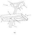
- Fig. 2 shows an alternative embodiment of the handle and the attachment for the support.
- a double handle 13 is provided, which runs around the stale 1.
- the double handle 13 thereby comprises two parallel cross members 14, 15, which are arranged on both sides of the stale 1 and at right angles to the latter.
- the first cross member 14 is arranged between the user and the stale 1, whilst the second cross member 15 is arranged beyond the stale 1, as viewed by the user.
- the two cross members 14, 15 are connected to one another on both sides of the stale 1 by side members 16.
- the two cross members 14, 15 are also joined by a two-way fastening attachment 17, which is fitted to the stale and serves to attach the double handle 13 to the stale.
- the fastening attachment 17 means that that the cross members 14, 15 are arranged at a distance from the stale in a direction at right angles to the stale.
- This alternative embodiment of the handle affords the user greater scope when choosing where to position his or her hands whilst working.
- the double handle 13 may be manufactured in one piece, although it may also be made up of separately manufactured and subsequently assembled parts 14, 15, 16, 17.
- the attachment of the support 3 differs from that in Fig. 1 in that the ball and socket joint is absent.
- the support is instead fixedly joined to the stale. It is nevertheless possible to combine the two embodiments of the handle 9, 13 and the different methods of attaching the support to the stale in any way.
- the support it is also possible for the support to be designed so that the stale is fixed to a belt worn by the user.
- Either a ball and socket joint may be used as described above, or a stale without a spherical ball may be attached to the belt by means of a flexible rubber holder. Both methods of attachment provide a moveable attachment of the stale to the user's belt.
- the handle 9, 13 may be attached to the stale 1 of the implement, for example, in that the fastening attachments 11, 17 comprise an opening 18, so that the fastening attachments 11, 17 can be slipped over the stale 1.
- a fixing screw which runs through a threaded hole in the fastening attachment can then fix the position of the fastening attachment in a longitudinal direction along the stale by tightening the screw against the stale.
- the diameter of the opening in the fastening attachments may be reduced in some way, for example by means of a screw or bolt, so that the fastening attachment clamps around the stale. This allows the position of the handles 9, 13 to be adjusted to suit different users.
- the handles may also constitute an integral part of the implement stale.
- the attachment of the handle 9, 13 it is also possible to design the attachment of the handle 9, 13 so that the handle can be angled to a position that is parallel, or substantially parallel to the stale. The user is thereby able to turn the handle 9, 13, if so desired, and can elect to work without the latter.
- the attachment of the handle 9, 13 can furthermore be designed so that the handle can be rotated about an axis at right angles to the stale, that is to say along an axis which is parallel to the longitudinal direction of the handle. This affords the user further scope in adopting a comfortable working position.
- Fig. 3 shows the handling of an implement 19 using the device for ergonomic handling 2 according to the first embodiment.
- Fig. 3 also shows the implement 19, in this case a mop, with associated stale 1 in its entirety.
- the user With his or her hands, the user holds both ends of the cross member 10, whilst allowing the support 3 to rest against their body.
- the mop is then propelled mainly by the user moving forwards so that the body exerts a pressure against the support 3 and hence against the mop stale.
- the user guides the mop laterally with their hands, which hold onto the cross member 10 of the handle 9.
- the mop is turned about the axis 20 perpendicular to the floor by turning the mop stale 1.
- the user can easily turn the mop stale with the aid of the cross member 10, which thereby provides a leverage effect.
- the device for ergonomic handling with the double handle 13 as shown in Fig. 2 provides several different ergonomic working positions. Depending on the desired working position, the user is free to choose whether to hold the first cross member 14, the second cross member 15, or the side members 16. The user can also hold the side member 16 on one side with one hand, and the other cross member 15 with the other hand.
- Fig. 4 shows an alternative embodiment of the mop stale.
- a gear mechanism 21 is provided with the ergonomic aim of enabling a slight deflection by the user to produce a large rotation of the mop head.
- the mop stale is here divided into two axially concentric sections, a first section 22 extending from the gear mechanism 21 to the user, and a second section 23 extending from the gear mechanism 21 to the mop 19.
- Fig. 4 shows a sketch diagram of the gear mechanism.
- a gear shaft 24 is arranged parallel with the stale 22, 23.
- On the gear shaft 24 a larger gear wheel 25 and a smaller gear wheel 26 are arranged at an axial distance from one another.
- the smaller gear wheel 26 on the shaft meshes with a first gear wheel 27 on the first section 22 of the stale.
- the larger gear wheel 25 on the shaft meshes with a second gear wheel 28 on the second section 23 of the stale.
- the first gear wheel 27 on the stale section 22 is larger than the second gear wheel 28 on the stale section 23.
- the gear wheel 27 on the first section 22 of the mop stale is the same size as the larger gear wheel 25 on the gear shaft 24, and the gear wheel 28 on the second section 23 of the mop stale is the same size as the smaller gear wheel 26 on the gear shaft 24.
- the large gear wheels 25, 27 have a diameter approximately three times greater than the small gear wheels 26, 28.
- a rotational movement of the first section 22 of the mop stale will thereby give rise to a rotation of the gear shaft 24 that is approximately three times greater.
- the rotation of the gear shaft 24 will in turn give rise to an approximately three times greater rotation of the second section 23 of the mop stale.
- the gearing therefore occurs in two stages. Consequently a deflection initiated by the user via the handle 9, 13 will give rise to a rotation of the mop head 19 that is approximately nine times greater.
- the user therefore only needs to turn the first section 22 of the mop stale through approximately 10° in order to produce a rotation of approximately 90° on the mop head 19.
- the sizes of the constituent gear wheels can be arbitrarily selected in order to obtain the desired geared transmission.
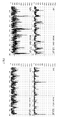
- Fig. 5 shows four electromyograms illustrating the effect of the invention.
- the activities of the right-hand and left-hand trapezius muscles are measured by electromyography (EMG) on a person using the device in Fig. 1 (the left-hand electromyogram) and a mop with conventional straight stale (the right-hand electromyogram).
- EMG electromyography
- the mean voltage measured in the trapezius muscle using the conventional mop stale was 1.8 ⁇ V on the left-hand side and 3.7 ⁇ V on the right-hand side.
- the mean voltages fell to 0,4 ⁇ V and 2.0 ⁇ V respectively. The device therefore has a marked effect on the muscular effort sustained when mopping.
Landscapes
- Engineering & Computer Science (AREA)
- Mechanical Engineering (AREA)
- Cleaning Implements For Floors, Carpets, Furniture, Walls, And The Like (AREA)
Applications Claiming Priority (1)
| Application Number | Priority Date | Filing Date | Title |
|---|---|---|---|
| SE0701474A SE532072C2 (sv) | 2007-06-15 | 2007-06-15 | Anordning för ergonomisk manövrering av ett verktyg, samt städverktyg |
Publications (4)
| Publication Number | Publication Date |
|---|---|
| EP2002942A2 true EP2002942A2 (de) | 2008-12-17 |
| EP2002942A3 EP2002942A3 (de) | 2009-12-16 |
| EP2002942B1 EP2002942B1 (de) | 2013-03-27 |
| EP2002942B8 EP2002942B8 (de) | 2013-07-10 |
Family
ID=39769506
Family Applications (1)
| Application Number | Title | Priority Date | Filing Date |
|---|---|---|---|
| EP08158187.8A Not-in-force EP2002942B8 (de) | 2007-06-15 | 2008-06-13 | Vorrichtung zum ergonomischen Umgang mit einem Einsatz und Reinigungseinsatz |
Country Status (4)
| Country | Link |
|---|---|
| EP (1) | EP2002942B8 (de) |
| DK (1) | DK2002942T3 (de) |
| ES (1) | ES2415681T3 (de) |
| SE (1) | SE532072C2 (de) |
Cited By (1)
| Publication number | Priority date | Publication date | Assignee | Title |
|---|---|---|---|---|
| USD746008S1 (en) * | 2012-04-04 | 2015-12-22 | Ahlstrom & Partners Ab | Mop handle |
Citations (2)
| Publication number | Priority date | Publication date | Assignee | Title |
|---|---|---|---|---|
| US5165144A (en) | 1986-01-31 | 1992-11-24 | Philip Nisenbaum | Tool handle and angularly adjustable attachment |
| GB2259663A (en) | 1991-09-17 | 1993-03-24 | Keith James Ryan | Device for facilitating the use of a long-handled ground-engaging implement |
Family Cites Families (3)
| Publication number | Priority date | Publication date | Assignee | Title |
|---|---|---|---|---|
| US4958407A (en) * | 1988-05-31 | 1990-09-25 | Johnson Samuel V | Auxiliary tool handle |
| US6598266B1 (en) * | 2000-06-29 | 2003-07-29 | Olin S. Elliott | Handle for a manually operated implement and method |
| WO2008007483A1 (en) * | 2006-07-10 | 2008-01-17 | Satoru Tanaya | Shoulder belt traction type hand-push tool |
-
2007
- 2007-06-15 SE SE0701474A patent/SE532072C2/sv not_active IP Right Cessation
-
2008
- 2008-06-13 ES ES08158187T patent/ES2415681T3/es active Active
- 2008-06-13 DK DK08158187.8T patent/DK2002942T3/da active
- 2008-06-13 EP EP08158187.8A patent/EP2002942B8/de not_active Not-in-force
Patent Citations (2)
| Publication number | Priority date | Publication date | Assignee | Title |
|---|---|---|---|---|
| US5165144A (en) | 1986-01-31 | 1992-11-24 | Philip Nisenbaum | Tool handle and angularly adjustable attachment |
| GB2259663A (en) | 1991-09-17 | 1993-03-24 | Keith James Ryan | Device for facilitating the use of a long-handled ground-engaging implement |
Cited By (1)
| Publication number | Priority date | Publication date | Assignee | Title |
|---|---|---|---|---|
| USD746008S1 (en) * | 2012-04-04 | 2015-12-22 | Ahlstrom & Partners Ab | Mop handle |
Also Published As
| Publication number | Publication date |
|---|---|
| SE532072C2 (sv) | 2009-10-13 |
| EP2002942A3 (de) | 2009-12-16 |
| DK2002942T3 (da) | 2013-06-17 |
| ES2415681T3 (es) | 2013-07-26 |
| SE0701474L (sv) | 2008-12-16 |
| EP2002942B8 (de) | 2013-07-10 |
| EP2002942B1 (de) | 2013-03-27 |
Similar Documents
| Publication | Publication Date | Title |
|---|---|---|
| US9532640B2 (en) | Ergonomic sweeping device | |
| US6170112B1 (en) | Push broom with bowed handle | |
| US9718181B2 (en) | Apparatus for ergonomic application of rotational handle garden tool | |
| US11926032B2 (en) | Tool handles having stationary and rotational portions | |
| US7637882B2 (en) | Multiple use handle support for distributing forces | |
| US7694392B2 (en) | Impact tools with slidable grip | |
| US20040055099A1 (en) | Ergonomic handle system for tool head | |
| US20110173778A1 (en) | Ergonomic auxiliary handle | |
| CN103402713A (zh) | 人体工学工具把手加强器 | |
| US6105194A (en) | Cleaning implement having a rotatable handle | |
| US9775272B1 (en) | Auxiliary handle attachment for a material-moving tool | |
| EP2965681A1 (de) | Griff für ein reinigungswerkzeug oder dergleichen | |
| US5832563A (en) | Forearm assistant device | |
| US20160374256A1 (en) | Method and apparatus for ergonomic application of rotational handle garden tool | |
| US20120048074A1 (en) | Hand Tool with Ergonomic Handle, and Ergonomic Handle for Hand Tool | |
| US9649656B2 (en) | Paint roller handle | |
| EP1761155B1 (de) | Moppgriff für eine moppvorrichtung | |
| US9889550B1 (en) | Step down handle for a hand tool | |
| US20040007887A1 (en) | Extendable handle for a manually operated implement and method | |
| EP3930568A1 (de) | Ergonomischer mast für ein gerät | |
| EP2002942B1 (de) | Vorrichtung zum ergonomischen Umgang mit einem Einsatz und Reinigungseinsatz | |
| US20050241110A1 (en) | Ergonomic handles, especially for garden tools | |
| US20100299855A1 (en) | Control apparatus | |
| US20130145909A1 (en) | Grip for a Tool Handle | |
| CN222485387U (zh) | 一种户外园林工具、骑乘式割草机、割草机的控制手柄 |
Legal Events
| Date | Code | Title | Description |
|---|---|---|---|
| PUAI | Public reference made under article 153(3) epc to a published international application that has entered the european phase |
Free format text: ORIGINAL CODE: 0009012 |
|
| AK | Designated contracting states |
Kind code of ref document: A2 Designated state(s): AT BE BG CH CY CZ DE DK EE ES FI FR GB GR HR HU IE IS IT LI LT LU LV MC MT NL NO PL PT RO SE SI SK TR |
|
| AX | Request for extension of the european patent |
Extension state: AL BA MK RS |
|
| PUAL | Search report despatched |
Free format text: ORIGINAL CODE: 0009013 |
|
| AK | Designated contracting states |
Kind code of ref document: A3 Designated state(s): AT BE BG CH CY CZ DE DK EE ES FI FR GB GR HR HU IE IS IT LI LT LU LV MC MT NL NO PL PT RO SE SI SK TR |
|
| AX | Request for extension of the european patent |
Extension state: AL BA MK RS |
|
| 17P | Request for examination filed |
Effective date: 20100528 |
|
| AKX | Designation fees paid |
Designated state(s): AT BE BG CH CY CZ DE DK EE ES FI FR GB GR HR HU IE IS IT LI LT LU LV MC MT NL NO PL PT RO SE SI SK TR |
|
| 17Q | First examination report despatched |
Effective date: 20100805 |
|
| REG | Reference to a national code |
Ref country code: DE Ref legal event code: R079 Ref document number: 602008023192 Country of ref document: DE Free format text: PREVIOUS MAIN CLASS: B25G0001100000 Ipc: A47L0013254000 |
|
| RIC1 | Information provided on ipc code assigned before grant |
Ipc: A47L 13/254 20060101AFI20120808BHEP Ipc: B25G 1/10 20060101ALI20120808BHEP |
|
| GRAP | Despatch of communication of intention to grant a patent |
Free format text: ORIGINAL CODE: EPIDOSNIGR1 |
|
| GRAS | Grant fee paid |
Free format text: ORIGINAL CODE: EPIDOSNIGR3 |
|
| GRAA | (expected) grant |
Free format text: ORIGINAL CODE: 0009210 |
|
| AK | Designated contracting states |
Kind code of ref document: B1 Designated state(s): AT BE BG CH CY CZ DE DK EE ES FI FR GB GR HR HU IE IS IT LI LT LU LV MC MT NL NO PL PT RO SE SI SK TR |
|
| REG | Reference to a national code |
Ref country code: GB Ref legal event code: FG4D |
|
| RIN1 | Information on inventor provided before grant (corrected) |
Inventor name: HAEGG, GOERAN M Inventor name: AHLSTROEM, JOHN P Inventor name: VAN LEER, JOHN |
|
| REG | Reference to a national code |
Ref country code: CH Ref legal event code: EP |
|
| REG | Reference to a national code |
Ref country code: AT Ref legal event code: REF Ref document number: 602830 Country of ref document: AT Kind code of ref document: T Effective date: 20130415 |
|
| REG | Reference to a national code |
Ref country code: IE Ref legal event code: FG4D |
|
| REG | Reference to a national code |
Ref country code: DE Ref legal event code: R096 Ref document number: 602008023192 Country of ref document: DE Effective date: 20130523 |
|
| REG | Reference to a national code |
Ref country code: DK Ref legal event code: T3 |
|
| RAP2 | Party data changed (patent owner data changed or rights of a patent transferred) |
Owner name: AHLSTROM & PARTNERS AB |
|
| REG | Reference to a national code |
Ref country code: ES Ref legal event code: FG2A Ref document number: 2415681 Country of ref document: ES Kind code of ref document: T3 Effective date: 20130726 |
|
| PG25 | Lapsed in a contracting state [announced via postgrant information from national office to epo] |
Ref country code: LT Free format text: LAPSE BECAUSE OF FAILURE TO SUBMIT A TRANSLATION OF THE DESCRIPTION OR TO PAY THE FEE WITHIN THE PRESCRIBED TIME-LIMIT Effective date: 20130327 Ref country code: BG Free format text: LAPSE BECAUSE OF FAILURE TO SUBMIT A TRANSLATION OF THE DESCRIPTION OR TO PAY THE FEE WITHIN THE PRESCRIBED TIME-LIMIT Effective date: 20130627 Ref country code: SE Free format text: LAPSE BECAUSE OF FAILURE TO SUBMIT A TRANSLATION OF THE DESCRIPTION OR TO PAY THE FEE WITHIN THE PRESCRIBED TIME-LIMIT Effective date: 20130327 |
|
| REG | Reference to a national code |
Ref country code: NO Ref legal event code: T2 Effective date: 20130327 |
|
| REG | Reference to a national code |
Ref country code: NL Ref legal event code: T3 |
|
| REG | Reference to a national code |
Ref country code: AT Ref legal event code: MK05 Ref document number: 602830 Country of ref document: AT Kind code of ref document: T Effective date: 20130327 |
|
| REG | Reference to a national code |
Ref country code: LT Ref legal event code: MG4D |
|
| PG25 | Lapsed in a contracting state [announced via postgrant information from national office to epo] |
Ref country code: GR Free format text: LAPSE BECAUSE OF FAILURE TO SUBMIT A TRANSLATION OF THE DESCRIPTION OR TO PAY THE FEE WITHIN THE PRESCRIBED TIME-LIMIT Effective date: 20130628 Ref country code: LV Free format text: LAPSE BECAUSE OF FAILURE TO SUBMIT A TRANSLATION OF THE DESCRIPTION OR TO PAY THE FEE WITHIN THE PRESCRIBED TIME-LIMIT Effective date: 20130327 Ref country code: SI Free format text: LAPSE BECAUSE OF FAILURE TO SUBMIT A TRANSLATION OF THE DESCRIPTION OR TO PAY THE FEE WITHIN THE PRESCRIBED TIME-LIMIT Effective date: 20130327 |
|
| PG25 | Lapsed in a contracting state [announced via postgrant information from national office to epo] |
Ref country code: BE Free format text: LAPSE BECAUSE OF FAILURE TO SUBMIT A TRANSLATION OF THE DESCRIPTION OR TO PAY THE FEE WITHIN THE PRESCRIBED TIME-LIMIT Effective date: 20130327 Ref country code: HR Free format text: LAPSE BECAUSE OF FAILURE TO SUBMIT A TRANSLATION OF THE DESCRIPTION OR TO PAY THE FEE WITHIN THE PRESCRIBED TIME-LIMIT Effective date: 20130327 |
|
| PG25 | Lapsed in a contracting state [announced via postgrant information from national office to epo] |
Ref country code: AT Free format text: LAPSE BECAUSE OF FAILURE TO SUBMIT A TRANSLATION OF THE DESCRIPTION OR TO PAY THE FEE WITHIN THE PRESCRIBED TIME-LIMIT Effective date: 20130327 Ref country code: PT Free format text: LAPSE BECAUSE OF FAILURE TO SUBMIT A TRANSLATION OF THE DESCRIPTION OR TO PAY THE FEE WITHIN THE PRESCRIBED TIME-LIMIT Effective date: 20130729 Ref country code: EE Free format text: LAPSE BECAUSE OF FAILURE TO SUBMIT A TRANSLATION OF THE DESCRIPTION OR TO PAY THE FEE WITHIN THE PRESCRIBED TIME-LIMIT Effective date: 20130327 Ref country code: IS Free format text: LAPSE BECAUSE OF FAILURE TO SUBMIT A TRANSLATION OF THE DESCRIPTION OR TO PAY THE FEE WITHIN THE PRESCRIBED TIME-LIMIT Effective date: 20130727 Ref country code: CZ Free format text: LAPSE BECAUSE OF FAILURE TO SUBMIT A TRANSLATION OF THE DESCRIPTION OR TO PAY THE FEE WITHIN THE PRESCRIBED TIME-LIMIT Effective date: 20130327 Ref country code: SK Free format text: LAPSE BECAUSE OF FAILURE TO SUBMIT A TRANSLATION OF THE DESCRIPTION OR TO PAY THE FEE WITHIN THE PRESCRIBED TIME-LIMIT Effective date: 20130327 Ref country code: RO Free format text: LAPSE BECAUSE OF FAILURE TO SUBMIT A TRANSLATION OF THE DESCRIPTION OR TO PAY THE FEE WITHIN THE PRESCRIBED TIME-LIMIT Effective date: 20130327 |
|
| PG25 | Lapsed in a contracting state [announced via postgrant information from national office to epo] |
Ref country code: PL Free format text: LAPSE BECAUSE OF FAILURE TO SUBMIT A TRANSLATION OF THE DESCRIPTION OR TO PAY THE FEE WITHIN THE PRESCRIBED TIME-LIMIT Effective date: 20130327 Ref country code: CY Free format text: LAPSE BECAUSE OF FAILURE TO SUBMIT A TRANSLATION OF THE DESCRIPTION OR TO PAY THE FEE WITHIN THE PRESCRIBED TIME-LIMIT Effective date: 20130327 |
|
| PG25 | Lapsed in a contracting state [announced via postgrant information from national office to epo] |
Ref country code: MC Free format text: LAPSE BECAUSE OF FAILURE TO SUBMIT A TRANSLATION OF THE DESCRIPTION OR TO PAY THE FEE WITHIN THE PRESCRIBED TIME-LIMIT Effective date: 20130327 |
|
| PLBE | No opposition filed within time limit |
Free format text: ORIGINAL CODE: 0009261 |
|
| REG | Reference to a national code |
Ref country code: CH Ref legal event code: PL |
|
| STAA | Information on the status of an ep patent application or granted ep patent |
Free format text: STATUS: NO OPPOSITION FILED WITHIN TIME LIMIT |
|
| 26N | No opposition filed |
Effective date: 20140103 |
|
| REG | Reference to a national code |
Ref country code: IE Ref legal event code: MM4A |
|
| REG | Reference to a national code |
Ref country code: DE Ref legal event code: R097 Ref document number: 602008023192 Country of ref document: DE Effective date: 20140103 |
|
| PG25 | Lapsed in a contracting state [announced via postgrant information from national office to epo] |
Ref country code: CH Free format text: LAPSE BECAUSE OF NON-PAYMENT OF DUE FEES Effective date: 20130630 Ref country code: LI Free format text: LAPSE BECAUSE OF NON-PAYMENT OF DUE FEES Effective date: 20130630 Ref country code: IE Free format text: LAPSE BECAUSE OF NON-PAYMENT OF DUE FEES Effective date: 20130613 |
|
| PG25 | Lapsed in a contracting state [announced via postgrant information from national office to epo] |
Ref country code: MT Free format text: LAPSE BECAUSE OF FAILURE TO SUBMIT A TRANSLATION OF THE DESCRIPTION OR TO PAY THE FEE WITHIN THE PRESCRIBED TIME-LIMIT Effective date: 20130327 |
|
| PG25 | Lapsed in a contracting state [announced via postgrant information from national office to epo] |
Ref country code: TR Free format text: LAPSE BECAUSE OF FAILURE TO SUBMIT A TRANSLATION OF THE DESCRIPTION OR TO PAY THE FEE WITHIN THE PRESCRIBED TIME-LIMIT Effective date: 20130327 |
|
| PG25 | Lapsed in a contracting state [announced via postgrant information from national office to epo] |
Ref country code: LU Free format text: LAPSE BECAUSE OF NON-PAYMENT OF DUE FEES Effective date: 20130613 Ref country code: HU Free format text: LAPSE BECAUSE OF FAILURE TO SUBMIT A TRANSLATION OF THE DESCRIPTION OR TO PAY THE FEE WITHIN THE PRESCRIBED TIME-LIMIT; INVALID AB INITIO Effective date: 20080613 |
|
| REG | Reference to a national code |
Ref country code: FR Ref legal event code: PLFP Year of fee payment: 9 |
|
| PGFP | Annual fee paid to national office [announced via postgrant information from national office to epo] |
Ref country code: FI Payment date: 20160609 Year of fee payment: 9 |
|
| PGFP | Annual fee paid to national office [announced via postgrant information from national office to epo] |
Ref country code: NL Payment date: 20160610 Year of fee payment: 9 |
|
| REG | Reference to a national code |
Ref country code: FR Ref legal event code: PLFP Year of fee payment: 10 |
|
| PGFP | Annual fee paid to national office [announced via postgrant information from national office to epo] |
Ref country code: FR Payment date: 20170630 Year of fee payment: 10 Ref country code: GB Payment date: 20170629 Year of fee payment: 10 |
|
| PGFP | Annual fee paid to national office [announced via postgrant information from national office to epo] |
Ref country code: DE Payment date: 20170703 Year of fee payment: 10 Ref country code: IT Payment date: 20170703 Year of fee payment: 10 Ref country code: ES Payment date: 20170703 Year of fee payment: 10 Ref country code: NO Payment date: 20170630 Year of fee payment: 10 |
|
| PGFP | Annual fee paid to national office [announced via postgrant information from national office to epo] |
Ref country code: DK Payment date: 20170630 Year of fee payment: 10 |
|
| REG | Reference to a national code |
Ref country code: NL Ref legal event code: MM Effective date: 20170701 |
|
| PG25 | Lapsed in a contracting state [announced via postgrant information from national office to epo] |
Ref country code: NL Free format text: LAPSE BECAUSE OF NON-PAYMENT OF DUE FEES Effective date: 20170701 |
|
| REG | Reference to a national code |
Ref country code: DE Ref legal event code: R119 Ref document number: 602008023192 Country of ref document: DE |
|
| REG | Reference to a national code |
Ref country code: DK Ref legal event code: EBP Effective date: 20180630 |
|
| REG | Reference to a national code |
Ref country code: NO Ref legal event code: MMEP |
|
| PG25 | Lapsed in a contracting state [announced via postgrant information from national office to epo] |
Ref country code: FI Free format text: LAPSE BECAUSE OF NON-PAYMENT OF DUE FEES Effective date: 20180613 |
|
| GBPC | Gb: european patent ceased through non-payment of renewal fee |
Effective date: 20180613 |
|
| PG25 | Lapsed in a contracting state [announced via postgrant information from national office to epo] |
Ref country code: FR Free format text: LAPSE BECAUSE OF NON-PAYMENT OF DUE FEES Effective date: 20180630 Ref country code: DE Free format text: LAPSE BECAUSE OF NON-PAYMENT OF DUE FEES Effective date: 20190101 Ref country code: GB Free format text: LAPSE BECAUSE OF NON-PAYMENT OF DUE FEES Effective date: 20180613 Ref country code: NO Free format text: LAPSE BECAUSE OF NON-PAYMENT OF DUE FEES Effective date: 20180630 Ref country code: IT Free format text: LAPSE BECAUSE OF NON-PAYMENT OF DUE FEES Effective date: 20180613 |
|
| PG25 | Lapsed in a contracting state [announced via postgrant information from national office to epo] |
Ref country code: DK Free format text: LAPSE BECAUSE OF NON-PAYMENT OF DUE FEES Effective date: 20180630 |
|
| REG | Reference to a national code |
Ref country code: ES Ref legal event code: FD2A Effective date: 20190916 |
|
| PG25 | Lapsed in a contracting state [announced via postgrant information from national office to epo] |
Ref country code: ES Free format text: LAPSE BECAUSE OF NON-PAYMENT OF DUE FEES Effective date: 20180614 |