EP2003009B1 - Bedienfeld, insbesondere für eine Klimaanlage eines Kraftfahrzeuges - Google Patents
Bedienfeld, insbesondere für eine Klimaanlage eines Kraftfahrzeuges Download PDFInfo
- Publication number
- EP2003009B1 EP2003009B1 EP07425380A EP07425380A EP2003009B1 EP 2003009 B1 EP2003009 B1 EP 2003009B1 EP 07425380 A EP07425380 A EP 07425380A EP 07425380 A EP07425380 A EP 07425380A EP 2003009 B1 EP2003009 B1 EP 2003009B1
- Authority
- EP
- European Patent Office
- Prior art keywords
- support
- control knob
- driven member
- control panel
- respect
- Prior art date
- Legal status (The legal status is an assumption and is not a legal conclusion. Google has not performed a legal analysis and makes no representation as to the accuracy of the status listed.)
- Not-in-force
Links
Images




Classifications
-
- G—PHYSICS
- G05—CONTROLLING; REGULATING
- G05G—CONTROL DEVICES OR SYSTEMS INSOFAR AS CHARACTERISED BY MECHANICAL FEATURES ONLY
- G05G1/00—Controlling members, e.g. knobs or handles; Assemblies or arrangements thereof; Indicating position of controlling members
- G05G1/08—Controlling members for hand actuation by rotary movement, e.g. hand wheels
- G05G1/10—Details, e.g. of discs, knobs, wheels or handles
Definitions
- the present invention relates to a control panel, in particular for controlling an air-conditioning assembly for vehicles. More precisely, the invention relates to a control panel comprising at least one rotary knob, connected via gears with a certain transmission ratio to a driven member.
- EP-A-1750292 discloses a control panel corresponding to the features of the preamble of claim 1.
- the object of the present invention is to provide a control panel that will enable coupling to one another of the control knob and the driven member in a pre-set relative angular position and without having to perform operations of adjustment.
- control panel having the characteristics forming the subject of Claim 1.
- control panel 10 designates a part of a control panel according to the present invention.
- the control panel 10 comprises a support 12 including two bodies coupled to one another in the way that will be described in what follows.
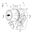
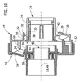
- Figures 1 to 6 designated by 14 is a first body of the support 12.
- the control panel 10 comprises at least one control knob 16, which can turn with respect to the support 12 about an axis 18.
- the knob 16 is preferably made of injection-moulded plastic material.
- the control knob 16 comprises a gear 20 sharing the axis of rotation 18 of the knob 16, preferably formed of a single piece with the body of the knob 16.
- the control knob 16 is moreover provided with an annular flange 22 projecting from an external circumferential wall 24 of the body of the knob 16.
- the annular flange 22 is preferably situated at the base of the toothing 20.
- the annular flange 22 is provided with a notch 26, the function of which will emerge clearly in the following of the description.
- the first body 14 of the support 12 is preferably made of injection-moulded plastic material and comprises a hub 28 with a cylindrical outer wall on which a cylindrical internal surface 30 of the control knob 16 is rotatably coupled.
- the first body 14 comprises a plurality of snap-engagement teeth 32 that are designed to engage the annular flange 22 of the control knob 16 so as to constrain the knob 16 to the first body 14 in the direction of the axis of rotation 16, leaving, however, the knob 16 free to turn about the axis 18.
- the first body 14 of the support 12 carries an idle gear 34, which can turn about an axis 36 parallel to the axis of rotation 18 of the control knob 16.
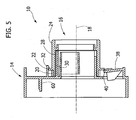
- the idle gear 34 is inserted in meshing contact with the toothing 20 of the control knob 16 when the knob 16 has been inserted on the hub 28 ( Figure 2 ).
- the first body 14 of the support 12 moreover comprises anelastically deformable tongue 38 which is integrally formed with the body 14 and is able to bend in the direction of the axis 18.
- the deformable tongue 38 has an end 40 that is designed to engage the notch 36 of the annular flange 22.
- the support 12 comprises a second body 42 designed to be coupled and fixed to the first body 14.
- the second body 42 is made of injected plastic material.
- the second body 42 has a seat 44, within which a driven member 46 is rotatably engaged.
- the driven member 46 can turn with respect to the second body 42 about an axis 48.
- the driven member 46 has a toothing 50 coaxial with the axis of rotation 48.
- the member 46 is moreover provided with an annular flange 52 similar to the annular flange 22 of the control knob 16.
- the annular flange 52 of the driven member 46 is provided with a notch 54 similar to the notch 26 of the control knob 16.
- the second body 42 of the support 12 is provided with a flexible tab 56, which is elastically deformable in the direction of the axis 48.
- the flexible tab 56 has an end 58 that is designed to engage the notch 54 of the annular flange 52.
- the control knob 16 is inserted in the direction of its own axis 18 on the hub 28 of the first body 14 in the direction indicated by the arrow in Figures 1 and 2 .
- the control knob 16 has a random angular orientation with respect to the first body 14.
- the teeth 32 engage by snap action the top side of the annular flange 22, axially withholding the control knob 16 with respect to the first body 14.
- the annular flange 22 interferes with the end 40 of the flexible tab 38 and produces elastic bending of the tab 38.
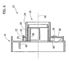
- the control knob 16 is turned about the axis 18 in the direction indicated by the arrow.
- the notch 26 of the annular flange 22 moves to the end 40 of the flexible tab 38.
- the flexible tab 38 returns into its undeformed condition, bringing the end 40 into engagement with the notch 26.
- the control knob 16 is blocked angularly with respect to the first body 14 and is withheld in a pre-set angular position.
- the driven member 46 is mounted on the second body 42 with a sequence substantially similar to the sequence of assembly of the control knob 16 on the first body 14.
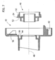
- a first step as illustrated in Figures 7 and 8 , the driven member 46 is inserted in the direction of its own axis 48 in the seat 44 of the second body 42.
- the angular orientation of the driven member 46 with respect to the second body 42 is random.
- the annular flange 52 of the driven member 46 interferes with the end 58 of the flexible tab 56 and elastically deforms the tab 56, as illustrated in Figure 8 .
- the driven member 46 is turned about its own axis 48 until engagement of the end 58 of the flexible tab 56 with the notch 54 (configuration of Figure 9 ) is obtained. In this condition, the driven member 46 is blocked in a pre-set angular position with respect to the second body 42.
- the first and second bodies 14, 42 are coupled to one another with a movement in the direction of the axes 18, 48.
- a member 60 for disengagement of the first body 14 acts on the flexible tab 56 of the second body 42.
- a member 62 for disengagement of the second body 42 acts on the flexible tab 38 of the first body 14.
- the disengagement members 60, 62 push the flexible tabs 56, 38 into an elastically deformed position, in which the respective ends 58, 40 are disengaged by the notches 54, 26.
- the control knob 16 and the driven member 46 are free to turn about the axes 18, 48.
- the toothing 50 of the driven member 46 engages the gear 36, carried by the first body 14 or else a further fixed gear coaxial with respect to the gear 36.
- the axes of rotation of the control knob 16 and of the driven member 46 are coincident with one another.
- the control knob 16 and the driven member 46 could be able to turn about non-coaxial parallel axes.
- system according to the present invention enables mounting of the control knob 16 and the driven member 46 pre-set in phase with one another, without any need to perform operations of adjustment or setting.
- the system according to the invention does not enable mutual coupling between the bodies 14, 42 if not in the condition in which the control knob 16 is in the correct phase relationship with respect to the driven member 46.
- control knob 16 and the driven member 46 could be mounted both on the same body 14 or 42.
- disengagement members 60, 62 would both be provided, on a body 14 or 42 complementary to the one carrying the control knob 16 and the driven member 46.
Landscapes
- Physics & Mathematics (AREA)
- General Physics & Mathematics (AREA)
- Engineering & Computer Science (AREA)
- Automation & Control Theory (AREA)
- Mechanical Control Devices (AREA)
- Air-Conditioning For Vehicles (AREA)
Claims (4)
- Steuerfeld, insbesondere für die Steuerung einer Klimaanlagen-Anordnung für Fahrzeuge, enthaltend:- eine Halterung (12);- wenigstens einen Steuerknopf (16), der sich im Bezug auf die Halterung (12) drehen kann; und- wenigstens ein angetriebenes Element (46), das sich im Bezug auf die Halterung (12) drehen kann und mit dem Steuerknopf (16) mit Hilfe von Zahnrädern (20, 34, 50) verbunden ist,wobei das Steuerfeld dadurch gekennzeichnet ist, dass die Halterung (12) eine erste und eine zweite Rückhalteeinrichtung (38, 56) enthält, die mit komplementären Rückhalteeinrichtungen (26, 54) des Steuerknopfes (16) und des angetriebenen Elementes (46) zusammenwirken, um den Steuerknopf (16) und das angetriebene Element (46) im Bezug auf die Halterung (12) auf entsprechende voreingestellte Winkelstellungen zu beschränken, und dadurch, dass die Halterung (12) einen ersten Körper (14) und einen zweiten Körper (42) enthält, die miteinander gekoppelt werden können und mit Löseeinrichtungen (60, 62) ausgestattet sind, die mit der ersten und der zweiten Rückhalteeinrichtung (38, 56) zusammenwirken, um den Steuerknopf (16) und das angetriebene Element (46) aus den entsprechenden Rückhalteeinrichtungen (38, 56) zu lösen, wenn der erste und der zweite Körper (14, 42) der Halterung (12) miteinander gekoppelt sind.
- Steuerfeld nach Anspruch 1, dadurch gekennzeichnet, dass die Rückhalteeinrichtungen flexible Nasen (38, 56) enthalten, die elastisch verformbar sind und mit Kerben (26, 54) zusammenwirken, die an ringförmigen Flanschen (22, 52) des Steuerknopfes (15) und des angetriebenen Elementes (46) vorgesehen sind.
- Steuerfeld nach Anspruch 2, dadurch gekennzeichnet, dass die Löseelemente (60, 62) die jeweiligen flexiblen Nasen (38, 56) in eine verformte Stellung drücken, in der die flexiblen Nasen (38, 56) von dem Steuerknopf (16) und dem angetriebenen Element (46) gelöst sind.
- Steuerfeld nach Anspruch 2 oder 3, dadurch gekennzeichnet, dass die flexiblen Nasen (38, 56) integral an wenigstens einem der Körper (14, 42) ausgebildet sind.
Priority Applications (4)
| Application Number | Priority Date | Filing Date | Title |
|---|---|---|---|
| EP07425380A EP2003009B1 (de) | 2007-06-15 | 2007-06-15 | Bedienfeld, insbesondere für eine Klimaanlage eines Kraftfahrzeuges |
| DE602007008215T DE602007008215D1 (de) | 2007-06-15 | 2007-06-15 | Bedienfeld, insbesondere für eine Klimaanlage eines Kraftfahrzeuges |
| AT07425380T ATE476313T1 (de) | 2007-06-15 | 2007-06-15 | Bedienfeld, insbesondere für eine klimaanlage eines kraftfahrzeuges |
| ES07425380T ES2348486T3 (es) | 2007-06-15 | 2007-06-15 | Panel de control, en particular para controlar un conjunto de aire acondicionado para vehículo. |
Applications Claiming Priority (1)
| Application Number | Priority Date | Filing Date | Title |
|---|---|---|---|
| EP07425380A EP2003009B1 (de) | 2007-06-15 | 2007-06-15 | Bedienfeld, insbesondere für eine Klimaanlage eines Kraftfahrzeuges |
Publications (2)
| Publication Number | Publication Date |
|---|---|
| EP2003009A1 EP2003009A1 (de) | 2008-12-17 |
| EP2003009B1 true EP2003009B1 (de) | 2010-08-04 |
Family
ID=38686706
Family Applications (1)
| Application Number | Title | Priority Date | Filing Date |
|---|---|---|---|
| EP07425380A Not-in-force EP2003009B1 (de) | 2007-06-15 | 2007-06-15 | Bedienfeld, insbesondere für eine Klimaanlage eines Kraftfahrzeuges |
Country Status (4)
| Country | Link |
|---|---|
| EP (1) | EP2003009B1 (de) |
| AT (1) | ATE476313T1 (de) |
| DE (1) | DE602007008215D1 (de) |
| ES (1) | ES2348486T3 (de) |
Family Cites Families (2)
| Publication number | Priority date | Publication date | Assignee | Title |
|---|---|---|---|---|
| JP4299090B2 (ja) * | 2003-09-24 | 2009-07-22 | 株式会社東海理化電機製作所 | 車両用空調装置の操作装置 |
| JP4636545B2 (ja) * | 2005-08-02 | 2011-02-23 | 株式会社東海理化電機製作所 | 車両用の空調スイッチ装置 |
-
2007
- 2007-06-15 EP EP07425380A patent/EP2003009B1/de not_active Not-in-force
- 2007-06-15 AT AT07425380T patent/ATE476313T1/de not_active IP Right Cessation
- 2007-06-15 ES ES07425380T patent/ES2348486T3/es active Active
- 2007-06-15 DE DE602007008215T patent/DE602007008215D1/de active Active
Also Published As
| Publication number | Publication date |
|---|---|
| ES2348486T3 (es) | 2010-12-07 |
| EP2003009A1 (de) | 2008-12-17 |
| ATE476313T1 (de) | 2010-08-15 |
| DE602007008215D1 (de) | 2010-09-16 |
Similar Documents
| Publication | Publication Date | Title |
|---|---|---|
| EP1065132A1 (de) | Elektrische Servolenkung | |
| EP1816016B1 (de) | Luftverteileinheit für ein Fahrzeug | |
| US9267550B2 (en) | Transmission shift device | |
| US20080197733A1 (en) | Electric Motor and Transmission Drive Unit For Actuators In A Motor Vehicle | |
| US11725723B2 (en) | One bump rotary monostable shifter | |
| EP2650561B1 (de) | Ausgangselement und mehrachsige antriebsvorrichtung | |
| US20120279336A1 (en) | Transmission drive unit | |
| CN106363550A (zh) | 具有公差补偿的定位装置、包括这种装置的汽车部件组以及利用公差补偿的定位方法 | |
| CN108349520B (zh) | 用于机动车辆的转向柱和用于制造转向柱的方法 | |
| US20120255385A1 (en) | Gear device and rotary actuator having the same | |
| CN112815088B (zh) | 用于选择性地耦联两个共轴地设置的轴的装置 | |
| US6382384B2 (en) | Clutch having reduced noise level and motor including such clutch | |
| EP3140568B1 (de) | Aktuatoranordnung mit lastmomentsperre | |
| EP3369968B1 (de) | Differenzialvorrichtung | |
| US11022188B2 (en) | Overload clutch | |
| US20130079189A1 (en) | Load-sensitive gear shifting apparatus | |
| US20040256937A1 (en) | Hobby servo enhancements | |
| US20120279335A1 (en) | Actuator | |
| EP2003009A1 (de) | Bedienfeld, insbesondere für eine Klimaanlage eines Kraftfahrzeuges | |
| US20200009940A1 (en) | Kinematics assembly | |
| US5882124A (en) | Needle bearing | |
| EP1122390A2 (de) | Kupplung und Motor mit einer derartigen Kupplung | |
| JP2004299540A (ja) | 車両用空調装置のリンク駆動機構 | |
| US20150040710A1 (en) | Shift device having rotational free travel for the shift shaft, and motor vehicle transmission having such shift device | |
| KR20230145443A (ko) | 커플링 장치가 장착된 변속기 시스템 |
Legal Events
| Date | Code | Title | Description |
|---|---|---|---|
| PUAI | Public reference made under article 153(3) epc to a published international application that has entered the european phase |
Free format text: ORIGINAL CODE: 0009012 |
|
| AK | Designated contracting states |
Kind code of ref document: A1 Designated state(s): AT BE BG CH CY CZ DE DK EE ES FI FR GB GR HU IE IS IT LI LT LU LV MC MT NL PL PT RO SE SI SK TR |
|
| AX | Request for extension of the european patent |
Extension state: AL BA HR MK RS |
|
| 17P | Request for examination filed |
Effective date: 20090608 |
|
| 17Q | First examination report despatched |
Effective date: 20090703 |
|
| AKX | Designation fees paid |
Designated state(s): AT BE BG CH CY CZ DE DK EE ES FI FR GB GR HU IE IS IT LI LT LU LV MC MT NL PL PT RO SE SI SK TR |
|
| GRAP | Despatch of communication of intention to grant a patent |
Free format text: ORIGINAL CODE: EPIDOSNIGR1 |
|
| GRAS | Grant fee paid |
Free format text: ORIGINAL CODE: EPIDOSNIGR3 |
|
| GRAA | (expected) grant |
Free format text: ORIGINAL CODE: 0009210 |
|
| AK | Designated contracting states |
Kind code of ref document: B1 Designated state(s): AT BE BG CH CY CZ DE DK EE ES FI FR GB GR HU IE IS IT LI LT LU LV MC MT NL PL PT RO SE SI SK TR |
|
| REG | Reference to a national code |
Ref country code: GB Ref legal event code: FG4D |
|
| REG | Reference to a national code |
Ref country code: CH Ref legal event code: EP |
|
| REG | Reference to a national code |
Ref country code: RO Ref legal event code: EPE |
|
| REG | Reference to a national code |
Ref country code: IE Ref legal event code: FG4D |
|
| REF | Corresponds to: |
Ref document number: 602007008215 Country of ref document: DE Date of ref document: 20100916 Kind code of ref document: P |
|
| REG | Reference to a national code |
Ref country code: ES Ref legal event code: FG2A Effective date: 20101124 |
|
| REG | Reference to a national code |
Ref country code: NL Ref legal event code: VDEP Effective date: 20100804 |
|
| LTIE | Lt: invalidation of european patent or patent extension |
Effective date: 20100804 |
|
| PG25 | Lapsed in a contracting state [announced via postgrant information from national office to epo] |
Ref country code: NL Free format text: LAPSE BECAUSE OF FAILURE TO SUBMIT A TRANSLATION OF THE DESCRIPTION OR TO PAY THE FEE WITHIN THE PRESCRIBED TIME-LIMIT Effective date: 20100804 Ref country code: AT Free format text: LAPSE BECAUSE OF FAILURE TO SUBMIT A TRANSLATION OF THE DESCRIPTION OR TO PAY THE FEE WITHIN THE PRESCRIBED TIME-LIMIT Effective date: 20100804 Ref country code: FI Free format text: LAPSE BECAUSE OF FAILURE TO SUBMIT A TRANSLATION OF THE DESCRIPTION OR TO PAY THE FEE WITHIN THE PRESCRIBED TIME-LIMIT Effective date: 20100804 Ref country code: LT Free format text: LAPSE BECAUSE OF FAILURE TO SUBMIT A TRANSLATION OF THE DESCRIPTION OR TO PAY THE FEE WITHIN THE PRESCRIBED TIME-LIMIT Effective date: 20100804 |
|
| PG25 | Lapsed in a contracting state [announced via postgrant information from national office to epo] |
Ref country code: CY Free format text: LAPSE BECAUSE OF FAILURE TO SUBMIT A TRANSLATION OF THE DESCRIPTION OR TO PAY THE FEE WITHIN THE PRESCRIBED TIME-LIMIT Effective date: 20100804 Ref country code: IS Free format text: LAPSE BECAUSE OF FAILURE TO SUBMIT A TRANSLATION OF THE DESCRIPTION OR TO PAY THE FEE WITHIN THE PRESCRIBED TIME-LIMIT Effective date: 20101204 Ref country code: PL Free format text: LAPSE BECAUSE OF FAILURE TO SUBMIT A TRANSLATION OF THE DESCRIPTION OR TO PAY THE FEE WITHIN THE PRESCRIBED TIME-LIMIT Effective date: 20100804 Ref country code: PT Free format text: LAPSE BECAUSE OF FAILURE TO SUBMIT A TRANSLATION OF THE DESCRIPTION OR TO PAY THE FEE WITHIN THE PRESCRIBED TIME-LIMIT Effective date: 20101206 Ref country code: SI Free format text: LAPSE BECAUSE OF FAILURE TO SUBMIT A TRANSLATION OF THE DESCRIPTION OR TO PAY THE FEE WITHIN THE PRESCRIBED TIME-LIMIT Effective date: 20100804 Ref country code: BG Free format text: LAPSE BECAUSE OF FAILURE TO SUBMIT A TRANSLATION OF THE DESCRIPTION OR TO PAY THE FEE WITHIN THE PRESCRIBED TIME-LIMIT Effective date: 20101104 |
|
| PG25 | Lapsed in a contracting state [announced via postgrant information from national office to epo] |
Ref country code: BE Free format text: LAPSE BECAUSE OF FAILURE TO SUBMIT A TRANSLATION OF THE DESCRIPTION OR TO PAY THE FEE WITHIN THE PRESCRIBED TIME-LIMIT Effective date: 20100804 Ref country code: LV Free format text: LAPSE BECAUSE OF FAILURE TO SUBMIT A TRANSLATION OF THE DESCRIPTION OR TO PAY THE FEE WITHIN THE PRESCRIBED TIME-LIMIT Effective date: 20100804 Ref country code: SE Free format text: LAPSE BECAUSE OF FAILURE TO SUBMIT A TRANSLATION OF THE DESCRIPTION OR TO PAY THE FEE WITHIN THE PRESCRIBED TIME-LIMIT Effective date: 20100804 Ref country code: GR Free format text: LAPSE BECAUSE OF FAILURE TO SUBMIT A TRANSLATION OF THE DESCRIPTION OR TO PAY THE FEE WITHIN THE PRESCRIBED TIME-LIMIT Effective date: 20101105 |
|
| PG25 | Lapsed in a contracting state [announced via postgrant information from national office to epo] |
Ref country code: DK Free format text: LAPSE BECAUSE OF FAILURE TO SUBMIT A TRANSLATION OF THE DESCRIPTION OR TO PAY THE FEE WITHIN THE PRESCRIBED TIME-LIMIT Effective date: 20100804 |
|
| PG25 | Lapsed in a contracting state [announced via postgrant information from national office to epo] |
Ref country code: SK Free format text: LAPSE BECAUSE OF FAILURE TO SUBMIT A TRANSLATION OF THE DESCRIPTION OR TO PAY THE FEE WITHIN THE PRESCRIBED TIME-LIMIT Effective date: 20100804 Ref country code: EE Free format text: LAPSE BECAUSE OF FAILURE TO SUBMIT A TRANSLATION OF THE DESCRIPTION OR TO PAY THE FEE WITHIN THE PRESCRIBED TIME-LIMIT Effective date: 20100804 Ref country code: CZ Free format text: LAPSE BECAUSE OF FAILURE TO SUBMIT A TRANSLATION OF THE DESCRIPTION OR TO PAY THE FEE WITHIN THE PRESCRIBED TIME-LIMIT Effective date: 20100804 |
|
| PLBE | No opposition filed within time limit |
Free format text: ORIGINAL CODE: 0009261 |
|
| STAA | Information on the status of an ep patent application or granted ep patent |
Free format text: STATUS: NO OPPOSITION FILED WITHIN TIME LIMIT |
|
| 26N | No opposition filed |
Effective date: 20110506 |
|
| REG | Reference to a national code |
Ref country code: DE Ref legal event code: R097 Ref document number: 602007008215 Country of ref document: DE Effective date: 20110506 |
|
| PG25 | Lapsed in a contracting state [announced via postgrant information from national office to epo] |
Ref country code: MT Free format text: LAPSE BECAUSE OF FAILURE TO SUBMIT A TRANSLATION OF THE DESCRIPTION OR TO PAY THE FEE WITHIN THE PRESCRIBED TIME-LIMIT Effective date: 20100804 |
|
| REG | Reference to a national code |
Ref country code: CH Ref legal event code: PL |
|
| REG | Reference to a national code |
Ref country code: IE Ref legal event code: MM4A |
|
| PG25 | Lapsed in a contracting state [announced via postgrant information from national office to epo] |
Ref country code: CH Free format text: LAPSE BECAUSE OF NON-PAYMENT OF DUE FEES Effective date: 20110630 Ref country code: IE Free format text: LAPSE BECAUSE OF NON-PAYMENT OF DUE FEES Effective date: 20110615 Ref country code: LI Free format text: LAPSE BECAUSE OF NON-PAYMENT OF DUE FEES Effective date: 20110630 |
|
| PG25 | Lapsed in a contracting state [announced via postgrant information from national office to epo] |
Ref country code: RO Free format text: LAPSE BECAUSE OF NON-PAYMENT OF DUE FEES Effective date: 20100804 |
|
| PG25 | Lapsed in a contracting state [announced via postgrant information from national office to epo] |
Ref country code: MC Free format text: LAPSE BECAUSE OF NON-PAYMENT OF DUE FEES Effective date: 20110630 |
|
| PG25 | Lapsed in a contracting state [announced via postgrant information from national office to epo] |
Ref country code: LU Free format text: LAPSE BECAUSE OF NON-PAYMENT OF DUE FEES Effective date: 20110615 |
|
| PG25 | Lapsed in a contracting state [announced via postgrant information from national office to epo] |
Ref country code: HU Free format text: LAPSE BECAUSE OF FAILURE TO SUBMIT A TRANSLATION OF THE DESCRIPTION OR TO PAY THE FEE WITHIN THE PRESCRIBED TIME-LIMIT Effective date: 20100804 |
|
| PGFP | Annual fee paid to national office [announced via postgrant information from national office to epo] |
Ref country code: GB Payment date: 20140618 Year of fee payment: 8 |
|
| PGFP | Annual fee paid to national office [announced via postgrant information from national office to epo] |
Ref country code: TR Payment date: 20140613 Year of fee payment: 8 |
|
| PGFP | Annual fee paid to national office [announced via postgrant information from national office to epo] |
Ref country code: DE Payment date: 20140829 Year of fee payment: 8 |
|
| PGFP | Annual fee paid to national office [announced via postgrant information from national office to epo] |
Ref country code: ES Payment date: 20150619 Year of fee payment: 9 |
|
| REG | Reference to a national code |
Ref country code: DE Ref legal event code: R119 Ref document number: 602007008215 Country of ref document: DE |
|
| GBPC | Gb: european patent ceased through non-payment of renewal fee |
Effective date: 20150615 |
|
| PG25 | Lapsed in a contracting state [announced via postgrant information from national office to epo] |
Ref country code: DE Free format text: LAPSE BECAUSE OF NON-PAYMENT OF DUE FEES Effective date: 20160101 Ref country code: GB Free format text: LAPSE BECAUSE OF NON-PAYMENT OF DUE FEES Effective date: 20150615 |
|
| REG | Reference to a national code |
Ref country code: FR Ref legal event code: PLFP Year of fee payment: 10 |
|
| REG | Reference to a national code |
Ref country code: FR Ref legal event code: PLFP Year of fee payment: 11 |
|
| PG25 | Lapsed in a contracting state [announced via postgrant information from national office to epo] |
Ref country code: TR Free format text: LAPSE BECAUSE OF NON-PAYMENT OF DUE FEES Effective date: 20150615 |
|
| PG25 | Lapsed in a contracting state [announced via postgrant information from national office to epo] |
Ref country code: ES Free format text: LAPSE BECAUSE OF NON-PAYMENT OF DUE FEES Effective date: 20160616 |
|
| REG | Reference to a national code |
Ref country code: FR Ref legal event code: PLFP Year of fee payment: 12 |
|
| REG | Reference to a national code |
Ref country code: ES Ref legal event code: FD2A Effective date: 20181203 |
|
| PGFP | Annual fee paid to national office [announced via postgrant information from national office to epo] |
Ref country code: IT Payment date: 20210608 Year of fee payment: 15 |
|
| PG25 | Lapsed in a contracting state [announced via postgrant information from national office to epo] |
Ref country code: IT Free format text: LAPSE BECAUSE OF NON-PAYMENT OF DUE FEES Effective date: 20220615 |
|
| PGFP | Annual fee paid to national office [announced via postgrant information from national office to epo] |
Ref country code: FR Payment date: 20230622 Year of fee payment: 17 |
|
| PG25 | Lapsed in a contracting state [announced via postgrant information from national office to epo] |
Ref country code: FR Free format text: LAPSE BECAUSE OF NON-PAYMENT OF DUE FEES Effective date: 20240630 |