EP2003014A2 - Vehicle seat with a pivotable shoulder and head area - Google Patents
Vehicle seat with a pivotable shoulder and head area Download PDFInfo
- Publication number
- EP2003014A2 EP2003014A2 EP08157999A EP08157999A EP2003014A2 EP 2003014 A2 EP2003014 A2 EP 2003014A2 EP 08157999 A EP08157999 A EP 08157999A EP 08157999 A EP08157999 A EP 08157999A EP 2003014 A2 EP2003014 A2 EP 2003014A2
- Authority
- EP
- European Patent Office
- Prior art keywords
- seat
- shoulder
- backrest
- head
- vehicle seat
- Prior art date
- Legal status (The legal status is an assumption and is not a legal conclusion. Google has not performed a legal analysis and makes no representation as to the accuracy of the status listed.)
- Granted
Links
Images


Classifications
-
- B—PERFORMING OPERATIONS; TRANSPORTING
- B60—VEHICLES IN GENERAL
- B60N—SEATS SPECIALLY ADAPTED FOR VEHICLES; VEHICLE PASSENGER ACCOMMODATION NOT OTHERWISE PROVIDED FOR
- B60N2/00—Seats specially adapted for vehicles; Arrangement or mounting of seats in vehicles
- B60N2/02—Seats specially adapted for vehicles; Arrangement or mounting of seats in vehicles the seat or part thereof being movable, e.g. adjustable
- B60N2/22—Seats specially adapted for vehicles; Arrangement or mounting of seats in vehicles the seat or part thereof being movable, e.g. adjustable the back-rest being adjustable
- B60N2/2222—Seats specially adapted for vehicles; Arrangement or mounting of seats in vehicles the seat or part thereof being movable, e.g. adjustable the back-rest being adjustable the back-rest having two or more parts
-
- B—PERFORMING OPERATIONS; TRANSPORTING
- B60—VEHICLES IN GENERAL
- B60N—SEATS SPECIALLY ADAPTED FOR VEHICLES; VEHICLE PASSENGER ACCOMMODATION NOT OTHERWISE PROVIDED FOR
- B60N2/00—Seats specially adapted for vehicles; Arrangement or mounting of seats in vehicles
- B60N2/80—Head-rests
- B60N2/806—Head-rests movable or adjustable
- B60N2/838—Tiltable
-
- B—PERFORMING OPERATIONS; TRANSPORTING
- B60—VEHICLES IN GENERAL
- B60N—SEATS SPECIALLY ADAPTED FOR VEHICLES; VEHICLE PASSENGER ACCOMMODATION NOT OTHERWISE PROVIDED FOR
- B60N2/00—Seats specially adapted for vehicles; Arrangement or mounting of seats in vehicles
- B60N2/68—Seat frames
- B60N2/688—Particular seat belt attachment and guiding
Definitions
- the present invention relates to a vehicle seat according to the preamble of claim 1, in particular a vehicle seat with a seat part and a backrest, wherein the seat part for positional adjustment of the seat relative to a mountable to the seat harboring vehicle base frame substantially horizontally displaceable in the forward and backward direction and the backrest is pivotable about its steepness in a substantially vertical direction at its lower end to the variability of its steepness.
- Such vehicle seats can be adjusted in a certain number of parameters to the person sitting on the seat. This includes, in addition to the spacing of the seat from the steering wheel of the vehicle and the steepness of the backrest, for example, a height-adjustable headboard. Furthermore, it is known, for example, to adjust other properties of such a seat, such as the hardness of the lumbar region. However, it may also be desirable for the person occupying such a seat to be able to adjust further properties of such a seat. In addition, it is of interest in such seats their safety and strength and also to allow a comfortable and safe belt guide.
- the present invention proposes to solve or at least partially improve these difficulties and problems a vehicle seat, which has in particular the features mentioned in the characterizing part of claim 1.
- a vehicle seat has a backrest having a contiguous shoulder and head area forming in the front area of the backrest the support surface for the shoulder and head of a person sitting on the seat, the lower end of this shoulder and head area in the middle section the backrest is pivotally mounted on the rigid frame.
- This has the advantage that the steepness of the shoulder and head area can be changed independently of the lower area of the backrest and in one operation.
- this has a belt deflection, which is attached to the rigid frame of the backrest. This is particularly important for the safety and strength of the seat, since an adjustment of the shoulder and head area thus has no effect on the attachment of the seat belt or in particular the belt deflection. As a result, a safe and comfortable belt guide is possible.
- the said belt deflection can be mounted laterally on the rigid frame of the backrest.
- the pivotable shoulder and head area can have side parts.
- the strengthening of the belt deflection on the rigid frame of the backrest can be done in this case by means of at least one fixing pin on the side of this rigid frame.
- such a vehicle seat may include means for limiting the pivotal movement of the shoulder and head portion of the seat.
- the means for limiting the pivoting movement may comprise at least one attached to the rear region of the shoulder and headband headband, which engage around a rigid frame of the backrest mounted crossbar, with complete pivotal movement of the shoulder and head portion of the seat in the reverse direction of this even to said Cross bar strikes, while fully swinging the shoulder and head region of the seat in the forward direction, the said headband strike the crossbeam.
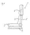
- a vehicle seat 1 a seat part 3 and a backrest 4, wherein the seat part 3 for positional adjustment of the seat relative to a base frame which is fixed to the seat-harboring vehicle, substantially horizontally in the forward and backward direction is displaceable for example, to control the distance to the steering wheel of the vehicle.
- the backrest 4 of a vehicle seat 1 according to the invention is pivotable at the variability of its steepness at its lower end. As is usual with such vehicle seats, it is possible for the person sitting on the seat to adapt the backrest to their needs. Just like this from the FIGS.
- a vehicle seat in particular a backrest having a contiguous shoulder and head area 6 or a head portion which forms the support surface for the shoulder and / or the head of sitting on the seat 1 person in the front region of the backrest 4 ,
- the lower end of this shoulder and head portion 6 is pivotally mounted in the central portion of the backrest 4 to the rigid frame 5.
- the pivot axis 6.4, on which the shoulder and head portion is pivotally mounted may be physically formed as a rod, or formed on either side of the rigid frame 5 by pins, or provided by other equivalent solutions. This solution makes it possible to provide for the shoulder and the head of the occupant a single, coherent total area, which can be pivoted approximately in the center of the backrest 4, depending on the needs of this person.
- such a seat 1 has a belt deflection 7 attached to the rigid frame 5 of the backrest 4.
- this said shoulder and head area 6 in the upper part of the backrest 4 is pivotally movable, on the other hand, however, the safety of the seat belt and in particular the necessary belt deflection is impaired in any way, insofar as it is indeed fixed in the rigid region of the backrest 4.
- this solution has no disadvantages compared to the previously common seats.
- the belt deflection 7 is attached laterally to the rigid frame 5 of the backrest 4 of a vehicle seat 1 according to the invention.
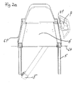
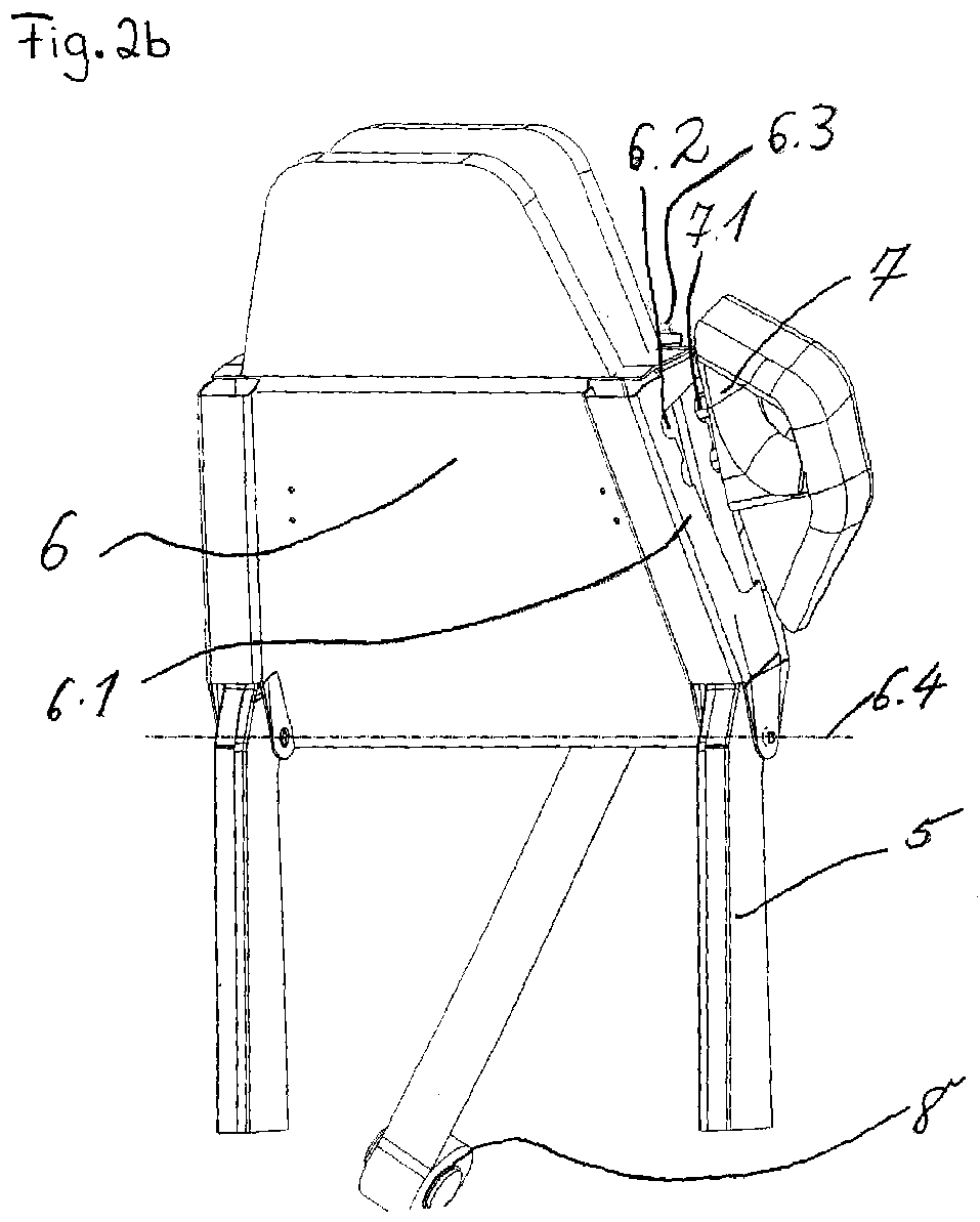
- the pivotable shoulder and head region 6 of such a vehicle seat normally has side parts 6.1, which, for example, also from the FIGS. 2a and 2 B can be seen.
- the belt deflection 7 in turn can be attached by means of at least one fastening pin 7.1 on the side region of the rigid frame 5 of the backrest 4.
- at least the side part 6.1 which is the Gurtumlenkung 7 adjacent, at least one corresponding through opening 6.2 for the mounting pins 7.1 to allow the pivoting movement of the shoulder and head portion 6 of the seat 1.
- This is in a schematic way, for example, the FIGS.
- the pivotable shoulder and head area 6 also has said side panels 6.1
- the belt deflection 7 can instead of fixing pins by means of at least one U-shaped part, whose open area is directed in the forward direction of the seat 1, on the back - And / or side area of the rigid frame 5 of the backrest 4 are attached.
- the pivoting movement of the shoulder and head region 6 of the seat 1 is thereby possible insofar as the side parts 6.1 of the shoulder and head region 6 are freely movable in the open region of the U-shaped parts.
- the belt deflection 7 normally has an approximately arcuate outer cover on the inner, rounded actual Gurt Adjuststeil, as well as about Fig. 2a seen.
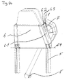
- a vehicle seat 1 according to the invention is shown in a perspective view from the side and from the back, it being apparent from this view, in particular, that such a seat may comprise means for limiting the pivoting movement of the shoulder and head area 6 of the seat 1.
- This means of limiting the Pivoting movement may consist of at least one attached to the rear portion of the shoulder and head portion headband 6.3, which engages a mounted on the rigid frame 5 of the backrest 4 crossbar 5.1, with complete pivoting of the shoulder and head portion 6 of the seat 1 in the reverse direction of this itself strikes said transom 5.1. With complete pivoting of the shoulder and head portion 6 of the seat 1 in the forward direction, however, beat the said bracket 6.3 on the crossbar 5.1.
- the means for limiting the pivoting movement can be formed by the passage openings 6.2 formed on the side parts 6.1 of the shoulder and head region 6 in interaction with the fastening pins 7.1 of the belt deflection 7 passing through them.
- the edge of said passage opening 6.2 beats at the end of the pivoting movement in each case to the corresponding attachment pin 7.1 of the belt deflection. In both cases, this makes it possible to achieve a simple and effective limitation of the pivoting movement of the shoulder and head region 6 of the vehicle seat 1 according to the invention.
- this Gurtaufrollvortechnisch 8 may preferably be secured in the lower rear portion of the seat 1, as for example in the FIGS. 4a and 4b is indicated schematically.
- this Gurtaufrollvortechnisch 8 can also be attached to a B pillar of the seat 1 harboring vehicle. In both cases, a safe and comfortable belt guide is thereby achieved.
- a seat 1 according to the invention naturally has corresponding upholstery parts and a cover, parts here again having a corresponding opening in the region of the belt deflection. Otherwise, these parts are well known to those skilled in the art and therefore require no further clarifications. It should only be mentioned that in this case both conventional upholstery and, for example, pneumatically controlled air chambers can be used.
- a vehicle seat according to the invention in general, as further advantages of a vehicle seat according to the invention to mention that by maintaining a fixed frame on the backrest whose strength and safety performance is maintained at the same level as in conventional vehicle seats, while at the same time bring the shoulder and head area in a separate tilt position leaves.
- the minimum or maximum inclination of this shoulder and head area can be limited by suitable means.
- This is also in relation to the safety of such a vehicle seat of concern, insofar as in an accident, the shoulder and head area is not moved arbitrarily.
- the fixation of the belt deflection on the fixed frame of the backrest is very important, as a result, the safety of such a seat is very high.
- the seat according to the invention has a modular construction, which favors in particular the easy replacement of the pivotable shoulder and head area. Further advantages will be apparent from the claims and from the foregoing detailed description of the present invention.
Landscapes
- Engineering & Computer Science (AREA)
- Aviation & Aerospace Engineering (AREA)
- Transportation (AREA)
- Mechanical Engineering (AREA)
- Automotive Seat Belt Assembly (AREA)
- Seats For Vehicles (AREA)
Abstract
Die Erfindung betrifft einen Fahrzeugsitz (1) mit einem Sitzteil (3) und einer Rückenlehne (4), wobei das Sitzteil (3) zur Positionsverstellung des Sitzes (1) gegenüber einem an dem den Sitz beherbergenden Fahrzeug befestigbaren Grundrahmen (2) im Wesentlichen horizontal in Vorwärts- und Rückwärtsrichtung verschiebbar und die Rückenlehne (4) zur Veränderbarkeit ihrer Steilheit in im Wesentlichen vertikaler Richtung an ihrem unteren Ende schwenkbar ist. Die Rückenlehne (4) weist einen zusammenhängenden Schulter- und Kopfbereich (6) auf, der im Vorderbereich der Rückenlehne (4) die Auflagefläche für die Schulter und den Kopf einer auf dem Sitz (1) sitzenden Person bildet, wobei das untere Ende dieses Schulter- und Kopfbereichs (6) im mittleren Abschnitt der Rückenlehne (4) an deren steifen Rahmen (5) schwenkbar angebracht ist.
Description
Die vorliegende Erfindung betrifft einen Fahrzeugsitz laut dem Oberbegriff des Anspruchs 1, insbesondere einen Fahrzeugsitz mit einem Sitzteil und einer Rückenlehne, wobei das Sitzteil zur Positionsverstellung des Sitzes gegenüber einen an dem den Sitz beherbergenden Fahrzeug befestigbaren Grundrahmen im Wesentlichen horizontal in Vorwärts- und Rückwärtsrichtung verschiebbar und die Rückenlehne zur Veränderbarkeit ihrer Steilheit in im Wesentlichen vertikaler Richtung an ihrem unteren Ende schwenkbar ist.The present invention relates to a vehicle seat according to the preamble of claim 1, in particular a vehicle seat with a seat part and a backrest, wherein the seat part for positional adjustment of the seat relative to a mountable to the seat harboring vehicle base frame substantially horizontally displaceable in the forward and backward direction and the backrest is pivotable about its steepness in a substantially vertical direction at its lower end to the variability of its steepness.
Derartige Fahrzeugsitze können in einer gewissen Anzahl von Parametern auf die auf dem Sitz sitzende Person eingestellt werden. Dazu gehört neben der Beabstandung des Sitzes vom Lenkrad des Fahrzeugs und der Steilheit der Rückenlehne zum Beispiel auch ein höhenverstellbares Kopfteil. Weiterhin ist es bekannt, beispielsweise auch andere Eigenschaften eines derartigen Sitzes, wie zum Beispiel die Härte des Lendenwirbelbereichs einstellen zu können. Es kann aber für die auf einem derartigen Sitz platznehmende Person auch wünschenswert sein, weitere Eigenschaften eines derartigen Sitzes verstellen zu können. Zudem ist es von Interesse, bei derartigen Sitzen deren Sicherheit sowie Festigkeit sowie außerdem eine komfortable und sichere Gurtführung zu ermöglichen.Such vehicle seats can be adjusted in a certain number of parameters to the person sitting on the seat. This includes, in addition to the spacing of the seat from the steering wheel of the vehicle and the steepness of the backrest, for example, a height-adjustable headboard. Furthermore, it is known, for example, to adjust other properties of such a seat, such as the hardness of the lumbar region. However, it may also be desirable for the person occupying such a seat to be able to adjust further properties of such a seat. In addition, it is of interest in such seats their safety and strength and also to allow a comfortable and safe belt guide.
Es ist daher die Aufgabe der vorliegenden Erfindung, bei derartigen Fahrzeugsitzen weitere Verstellmöglichkeiten, insbesondere im Schulter- und Kopfbereich vorzusehen, sowie die Sicherheit derartiger Sitze im Allgemeinen und in Bezug auf die dabei vorzunehmende Gurtführung und dessen Komfortabilität zu verbessern.It is therefore the object of the present invention to provide further adjustment options, in particular in the shoulder and head area, as well as to improve the safety of such seats in general and with respect to the belt guide to be made thereby and its comfortableness in such vehicle seats.
Die vorliegende Erfindung schlägt zur Lösung bzw. zumindest zur teilweisen Verbesserung dieser Schwierigkeiten und Probleme einen Fahrzeugsitz vor, der insbesondere die im kennzeichnenden Teil des Anspruchs 1 genannten Merkmale aufweist. Ein derartiger Fahrzeugsitz besitzt insbesondere eine Rückenlehne, die einen zusammenhängenden Schulter- und Kopfbereich aufweist, der im Vorderbereich der Rückenlehne die Auflagefläche für die Schulter und den Kopf einer auf dem Sitz sitzenden Person bildet, wobei das untere Ende dieses Schulter- und Kopfbereichs im mittleren Abschnitt der Rückenlehne an deren steifen Rahmen schwenkbar angebracht ist. Dies hat den Vorteil, dass sich die Steilheit des Schulter- und Kopfbereichs unabhängig vom unteren Bereich der Rückenlehne und in einem Vorgang verändern lässt.The present invention proposes to solve or at least partially improve these difficulties and problems a vehicle seat, which has in particular the features mentioned in the characterizing part of claim 1. In particular, such a vehicle seat has a backrest having a contiguous shoulder and head area forming in the front area of the backrest the support surface for the shoulder and head of a person sitting on the seat, the lower end of this shoulder and head area in the middle section the backrest is pivotally mounted on the rigid frame. This has the advantage that the steepness of the shoulder and head area can be changed independently of the lower area of the backrest and in one operation.
In einer bevorzugten Ausführungsform des Sitzes weist dieser eine Gurtumlenkung auf, die am steifen Rahmen der Rückenlehne angebracht ist. Dies ist insbesondere wichtig für die Sicherheit und Festigkeit des Sitzes, da eine Verstellung des Schulter- und Kopfbereichs somit auf die Anbringung des Anschnallgurts bzw. insbesondere die Gurtumlenkung keinerlei Einfluss hat. Dadurch ist eine sichere und komfortable Gurtführung möglich.In a preferred embodiment of the seat, this has a belt deflection, which is attached to the rigid frame of the backrest. This is particularly important for the safety and strength of the seat, since an adjustment of the shoulder and head area thus has no effect on the attachment of the seat belt or in particular the belt deflection. As a result, a safe and comfortable belt guide is possible.
Insbesondere kann die besagte Gurtumlenkung seitlich am steifen Rahmen der Rückenlehne angebracht sein. Vor allem kann der schwenkbare Schulter- und Kopfbereich Seitenteile aufweisen. Die Festigung der Gurtumlenkung am steifen Rahmen der Rückenlehne kann in diesem Fall mittels zumindest eines Befestigungsstifts am Seitenbereich dieses steifen Rahmens erfolgen. An dem Seitenteil, das der Gurtumlenkung benachbart liegt, ist dann zumindest eine entsprechende Durchgangsöffnung für diese Befestigungsstifte vorgesehen, um die Schwenkbewegung des Schulter- und Kopfbereichs des Sitzes zu erlauben.In particular, the said belt deflection can be mounted laterally on the rigid frame of the backrest. Above all, the pivotable shoulder and head area can have side parts. The strengthening of the belt deflection on the rigid frame of the backrest can be done in this case by means of at least one fixing pin on the side of this rigid frame. At the side part, which is adjacent to the belt deflection, then at least one corresponding passage opening for these mounting pins is provided to allow the pivoting movement of the shoulder and head portion of the seat.
Weiterhin kann ein derartiger Fahrzeugsitz Mittel zur Begrenzung der Schwenkbewegung des Schulter- und Kopfbereichs des Sitzes aufweisen. Insbesondere können die Mittel zur Begrenzung der Schwenkbewegung zumindest einen am hinteren Bereich des Schulter- und Kopfbereichs befestigten Haltebügel aufweisen, die einen am steifen Rahmen der Rückenlehne angebrachten Querbalken umgreifen, wobei bei vollständiger Schwenkbewegung des Schulter- und Kopfbereichs des Sitzes in Rückwärtsrichtung dieser selbst an besagtem Querbalken anschlägt, während bei vollständiger Schwenkung des Schulter- und Kopfbereichs des Sitzes in Vorwärtsrichtung die besagten Haltebügel am Querbalken anschlagen.Furthermore, such a vehicle seat may include means for limiting the pivotal movement of the shoulder and head portion of the seat. In particular, the means for limiting the pivoting movement may comprise at least one attached to the rear region of the shoulder and headband headband, which engage around a rigid frame of the backrest mounted crossbar, with complete pivotal movement of the shoulder and head portion of the seat in the reverse direction of this even to said Cross bar strikes, while fully swinging the shoulder and head region of the seat in the forward direction, the said headband strike the crossbeam.
Dadurch kann die Schwenkbewegung des Schulter- und Kopfbereichs des Sitzes in beiden Richtungen auf einfache Art und Weise begrenzt werden.Thereby, the pivotal movement of the shoulder and head portion of the seat can be limited in both directions in a simple manner.
Weiterhin ist es bei einem derartigen Fahrzeugsitz in vorteilhafter Weise möglich, die zur Aufrollung des Anschnallgurts benötigte Gurtaufrollvorrichtung entweder im unteren, hinteren Bereich des Sitzes oder an einer B-Säule des den Sitz beherbergenden Fahrzeugs zu befestigen. Auch dies erhöht die Sicherheit für den Benutzer eines derartigen Fahrzeugsitzes und erlaubt eine komfortable und sichere Gurtführung.Furthermore, in such a vehicle seat, it is advantageously possible to fasten the belt retractor required for reeling in the seat belt either in the lower, rear region of the seat or on a B pillar of the seat-hugging vehicle. This also increases the safety for the user of such a vehicle seat and allows a comfortable and secure belt guide.
Die beiliegenden Abbildungen zeigen einen erfindungsgemäßen Fahrzeugsitz in schematischer und beispielhafter Weise.
- Fig. 1
- zeigt eine seitliche Gesamtansicht eines erfindungsgemäßen Fahrzeugsitzes;
- Fig. 2a
- zeigt eine Vorderansicht eines derartigen Fahrzeugsitzes, wobei der schwenkbare Schulter- und Kopfbereich in zwei Positionen eingezeichnet ist;
- Fig. 2b
- ist eine perspektivische Ansicht von vorne seitlich auf einen erfindungsgemäßen Fahrzeugsitz, wobei wiederum zwei Positionen des schwenkbaren Schulter- und Kopfbereichs eingezeichnet sind;
- Fig. 3a
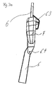
- zeigt einen erfindungsgemäßen Fahrzeugsitz von der Seite her gesehen, wobei der Schulter- und Kopfbereich nach hinten geklappt ist;
- Fig. 3b
- ist eine zu
Fig. 3a analoge Ansicht, wobei der schwenkbare Schulter- und Kopfbereich nach vorne geklappt ist; - Fig. 4a
- ist eine schematische perspektivische Ansicht von hinten auf einen erfindungsgemäßen Fahrzeugsitz, wobei der schwenkbare Schulter- und Kopfbereich nach hinten geklappt ist, und wo, wie in den vorhergehenden Abbildungen wiederum nur der Rückenlehnenbereich dargestellt ist; und
- Fig. 4b
- ist eine zu
Fig. 4a analoge perspektivische Ansicht, wobei der schwenkbare Schulter- und Kopfbereich nach vorne geklappt ist.
- Fig. 1
- shows a side overall view of a vehicle seat according to the invention;
- Fig. 2a
- shows a front view of such a vehicle seat, wherein the pivotable shoulder and head area is shown in two positions;
- Fig. 2b
- is a perspective view from the front side of a vehicle seat according to the invention, wherein in turn two positions of the pivotable shoulder and head area are shown;
- Fig. 3a
- shows a vehicle seat according to the invention seen from the side, wherein the shoulder and head area is folded backwards;
- Fig. 3b
- is one too
Fig. 3a analogue view, with the pivoting shoulder and head area folded forward; - Fig. 4a
- is a schematic perspective view from behind of a vehicle seat according to the invention, wherein the pivotable shoulder and head area is folded backwards, and where, as in the previous figures again only the backrest portion is shown; and
- Fig. 4b
- is one too
Fig. 4a analogous perspective view, with the pivoting shoulder and head area is folded forward.
Im Folgenden wird die vorliegende Erfindung unter Verweis auf die oben genannten Abbildungen im Detail beschrieben werden.Hereinafter, the present invention will be described in detail with reference to the above-mentioned drawings.
Wie dies der
In diesem Zusammenhang ist es insbesondere von Vorteil, dass ein derartiger Sitz 1 eine am steifen Rahmen 5 der Rückenlehne 4 angebrachte Gurtumlenkung 7 aufweist. Dadurch ist zwar der besagte Schulter- und Kopfbereich 6 im oberen Teil der Rückenlehne 4 schwenkbar beweglich, andererseits wird jedoch die Sicherheit des Anschnallgurts und insbesondere die hierfür notwendige Gurtumlenkung in keiner Weise beeinträchtigt, insofern diese ja im steifen Bereich der Rückenlehne 4 befestigt ist. Auch hinsichtlich des Komforts der Gurtführung weist diese Lösung keinerlei Nachteile im Vergleich zu den vorher üblichen Sitzen auf.In this context, it is particularly advantageous that such a seat 1 has a
In einer bevorzugten Ausführungsform wird die Gurtumlenkung 7 seitlich am steifen Rahmen 5 der Rückenlehne 4 eines erfindungsgemäßen Fahrzeugsitzes 1 angebracht. Zudem besitzt der schwenkbare Schulter- und Kopfbereich 6 eines derartigen Fahrzeugsitzes normalerweise Seitenteile 6.1, die beispielsweise ebenfalls aus den
Bei einer alternativen Ausführungsform eines erfindungsgemäßen Fahrzeugsitzes 1, deren schwenkbarer Schulter- und Kopfbereich 6 ebenfalls besagte Seitenteile 6.1 aufweist, kann die Gurtumlenkung 7 anstatt mit Befestigungsstiften mittels zumindest eines U-förmigen Teils, dessen offener Bereich in Vorwärtsrichtung des Sitzes 1 gerichtet ist, am Rücken- und/oder Seitenbereich des steifen Rahmens 5 der Rückenlehne 4 angebracht werden. Die Schwenkbewegung des Schulter- und Kopfbereichs 6 des Sitzes 1 ist dadurch möglich, insofern die Seitenteile 6.1 des Schulter- und Kopfbereichs 6 frei im offenen Bereich der U-förmigen Teile beweglich sind. Es lässt sich noch anmerken, dass die Gurtumlenkung 7 normalerweise eine in etwa bogenförmige äußere Abdeckung auf dem inneren, gerundeten eigentlichen Gurtführungsteil aufweist, sowie etwa aus
In den
Wie bei derartigen Fahrzeugsitzen 1 üblich, muss der durch die Gurtumlenkung 7 laufende Gurt mittels einer Gurtaufrollvorrichtung 8 aufrollbar sein. Bei einem erfindungsgemäßen Fahrzeugsitz 1 kann diese Gurtaufrollvorrichtung 8 vorzugsweise im unteren, hinteren Bereich des Sitzes 1 befestigt sein, so wie dies beispielsweise in den
Abschließend sei noch angemerkt, dass ein erfindungsgemäßer Sitz 1 natürlich entsprechende Polsterteile und einen Bezug aufweist, wobei hier Teile im Bereich der Gurtumlenkung wiederum eine entsprechende Öffnung besitzen. Ansonsten sind diese Teile dem Fachmann hinreichend bekannt und erfordert daher keine weiteren Präzisierungen. Es sei lediglich erwähnt, dass hierbei sowohl übliche Polster als auch zum Beispiel pneumatisch gesteuerte Luftkammern zum Einsatz kommen können.Finally, it should be noted that a seat 1 according to the invention naturally has corresponding upholstery parts and a cover, parts here again having a corresponding opening in the region of the belt deflection. Otherwise, these parts are well known to those skilled in the art and therefore require no further clarifications. It should only be mentioned that in this case both conventional upholstery and, for example, pneumatically controlled air chambers can be used.
Generell sind als weitere Vorteile eines erfindungsgemäßen Fahrzeugsitzes zu nennen, dass durch die Beibehaltung eines fixen Rahmens an der Rückenlehne deren Festigkeit und Sicherheitstauglichkeit auf dem selben Niveau wie bei üblichen Fahrzeugsitzen gehalten wird, während zugleich sich der Schulter- und Kopfbereich in eine separate Neigungslage bringen lässt. Wie vor dem erwähnt, kann die minimale bzw. maximale Neigung dieses Schulter- und Kopfbereichs mittels geeigneter Mittel begrenzt werden. Dies ist auch in Bezug auf die Sicherheit eines derartigen Fahrzeugsitzes von Belang, insofern dadurch bei einem Unfall der Schulter- und Kopfbereich nicht beliebig bewegt wird. In derartigen Situationen ist insbesondere die Fixierung der Gurtumlenkung am fixen Rahmen der Rückenlehne sehr wichtig, da hierdurch die Sicherheit eines derartigen Sitzes sehr hoch ist. Weiterhin ist zu erwähnen, dass der erfindungsgemäße Sitz eine modulare Bauweise besitzt, die insbesondere den leichten Austausch des schwenkbaren Schulter- und Kopfbereichs favorisiert. Weitere Vorteile ergeben sich aus den Ansprüchen sowie aus der vorstehenden detaillierten Beschreibung der vorliegenden Erfindung.In general, as further advantages of a vehicle seat according to the invention to mention that by maintaining a fixed frame on the backrest whose strength and safety performance is maintained at the same level as in conventional vehicle seats, while at the same time bring the shoulder and head area in a separate tilt position leaves. As mentioned before, the minimum or maximum inclination of this shoulder and head area can be limited by suitable means. This is also in relation to the safety of such a vehicle seat of concern, insofar as in an accident, the shoulder and head area is not moved arbitrarily. In such situations, in particular, the fixation of the belt deflection on the fixed frame of the backrest is very important, as a result, the safety of such a seat is very high. It should also be mentioned that the seat according to the invention has a modular construction, which favors in particular the easy replacement of the pivotable shoulder and head area. Further advantages will be apparent from the claims and from the foregoing detailed description of the present invention.
Sämtliche in den Anmeldungsunterlagen offenbarten Merkmale werden als erfindungswesentlich beansprucht, sofern sie einzeln oder in Kombination gegenüber dem Stand der Technik neu sind.All disclosed in the application documents features are claimed as essential to the invention, provided they are new individually or in combination over the prior art.
- 11
- Fahrzeugsitzvehicle seat
- 22
- Grundrahmenbase frame
- 33
- Sitzteilseat part
- 44
- Rückenlehnebackrest
- 55
- steifer Rahmen der RückenlehneStiff frame of the backrest
- 66
- schwenkbarer Schulter- und Kopfbereichswiveling shoulder and head area
- 6.16.1
- Seitenteile des schwenkbaren Kopf- und SchulterbereichsSide parts of the swiveling head and shoulder area
- 6.26.2
- DurchgangsöffnungenThrough openings
- 6.36.3
- Haltebügelheadband
- 6.46.4
- Schwenkachseswivel axis
- 77
- Gurtumlenkungbelt deflector
- 7.17.1
- Befestigungsstifte der GurtumlenkungFixing pins of the belt deflection
- 88th
- Gurtaufrollvorrichtungwebbing take
Claims (10)
dadurch gekennzeichnet, dass
die Rückenlehne (4) einen zusammenhängenden Schulter- und Kopfbereich (6) aufweist, der im Vorderbereich der Rückenlehne (4) die Auflagefläche für die Schulter und den Kopf einer auf dem Sitz (1) sitzenden Person bildet, wobei das untere Ende dieses Schulter- und Kopfbereichs (6) im mittleren Abschnitt der Rückenlehne (4) an deren steifen Rahmen (5) schwenkbar angebracht ist.Vehicle seat (1) having a seat part (3) and a backrest (4), wherein the seat part (3) for adjusting the position of the seat (1) relative to a base frame (2) attachable to the seat-hugging vehicle substantially horizontally in forward and Displaceable in the backward direction and the backrest (4) is pivotable at its lower end in order to be able to change its steepness in a substantially vertical direction,
characterized in that
the backrest (4) has a contiguous shoulder and head area (6) which in the front area of the backrest (4) forms the support surface for the shoulder and the head of a person sitting on the seat (1), the lower end of this shoulder area and head portion (6) in the central portion of the backrest (4) is pivotally mounted on the rigid frame (5).
dadurch gekennzeichnet, dass
der Sitz (1) eine am steifen Rahmen (5) der Rückenlehne (4) angebrachte Gurtumlenkung (7) aufweist.Vehicle seat (1) according to the preceding claim,
characterized in that
the seat (1) has a belt deflection (7) attached to the rigid frame (5) of the backrest (4).
dadurch gekennzeichnet, dass
die Gurtumlenkung (7) seitlich am steifen Rahmen (5) der Rückenlehne (4) angebracht ist.Vehicle seat (1) according to the preceding claim,
characterized in that
the belt deflector (7) is mounted laterally on the rigid frame (5) of the backrest (4).
dadurch gekennzeichnet, dass
der schwenkbare Schulter- und Kopfbereich (6) Seitenteile (6.1) aufweist, wobei die Gurtumlenkung (7) mittels zumindest eines Befestigungsstifts (7.1) am Seitenbereich des steifen Rahmens (5) der Rückenlehne (4) angebracht ist, und wobei zumindest an dem Seitenteil (6.1), das der Gurtumlenkung (7) benachbart liegt, zumindest eine entsprechende Durchgangsöffnung (6.2) für die Befestigungsstifte (7.1) vorgesehen ist, um die Schwenkbewegung des Schulter- und Kopfbereichs (6) des Sitzes (1) zu erlauben.Vehicle seat (1) according to the preceding claim,
characterized in that
the pivotable shoulder and head region (6) has side parts (6.1), wherein the belt deflection (7) is attached to the side region of the rigid frame (5) of the backrest (4) by means of at least one fastening pin (7.1), and wherein at least on the side part (6.1), which is the Gurtumlenkung (7) adjacent, at least one corresponding through hole (6.2) for the mounting pins (7.1) is provided to allow the pivotal movement of the shoulder and head portion (6) of the seat (1).
dadurch gekennzeichnet, dass
der schwenkbare Schulter- und Kopfbereich (6) Seitenteile (6.1) aufweist, wobei die Gurtumlenkung (7) mittels zumindest eines U-förmigen Teils, dessen offener Bereich in Vorwärtsrichtung des Sitzes (1) gerichtet ist, derart am Rücken- und/oder Seitenbereich des steifen Rahmens (5) der Rückenlehne (4) angebracht ist, dass sie die Schwenkbewegung des Schulter- und Kopfbereichs (6) des Sitzes (1) erlaubt, indem die Seitenteile (6.1) des Schulter- und Kopfbereichs (6) frei im offenen Bereich der U-förmigen Teile beweglich sind.Vehicle seat (1) according to claim 3,
characterized in that
the pivotable shoulder and head area (6) has side parts (6.1), wherein the belt deflection (7) is directed by means of at least one U-shaped part whose open area is directed in the forward direction of the seat (1), in the back and / or side area the rigid frame (5) of the backrest (4) is mounted so that it allows the pivoting movement of the shoulder and head region (6) of the seat (1) by the side parts (6.1) of the shoulder and head region (6) free in the open Area of U-shaped parts are movable.
dadurch gekennzeichnet, dass
er Mittel zur Begrenzung der Schwenkbewegung des Schulter- und Kopfbereichs (6) des Sitzes (1) aufweist.Vehicle seat (1) according to one of the preceding claims,
characterized in that
it comprises means for limiting the pivoting movement of the shoulder and head region (6) of the seat (1).
dadurch gekennzeichnet, dass
die Mittel zur Begrenzung der Schwenkbewegung zumindest einen am hinteren Bereich des Schulter- und Kopfbereichs befestigten Haltebügel (6.3) aufweisen, der einen am steifen Rahmen (5) der Rückenlehne (4) angebrachten Querbalken (5.1) umgreift, wobei bei vollständiger Schwenkung des Schulter- und Kopfbereichs (6) des Sitzes (1) in Rückwärtsrichtung dieser selbst an besagtem Querbalken (5.1) anschlägt, während bei vollständiger Schwenkung des Schulter- und Kopfbereichs (6) des Sitzes (1) in Vorwärtsrichtung die besagten Haltebügel (6.3) am Querbalken (5.1) anschlagen.Vehicle seat (1) according to the preceding claim,
characterized in that
the means for limiting the pivoting movement comprise at least one retaining bracket (6.3) fastened to the rear region of the shoulder and head region, which encompasses a crossbeam (5.1) attached to the rigid frame (5) of the backrest (4), with complete pivoting of the shoulder and head portion (6) of the seat (1) in the reverse direction of the latter itself abuts against said crossbar (5.1), while with complete pivoting of the shoulder and head portion (6) of the seat (1) in the forward direction, said retaining bracket (6.3) on the crossbar ( 5.1).
dadurch gekennzeichnet, dass
die Mittel zur Begrenzung der Schwenkbewegung durch die an den Seitenteilen (6.1) des Schulter- und Kopfbereichs (6) geformten Durchgangsöffnungen (6.2) im Zusammenspiel mit den durch diese hindurchgehenden Befestigungsstiften (7.1) der Gurtumlenkung (7) gebildet werden.Vehicle seat (1) according to claims 4 and 6,
characterized in that
the means for limiting the pivoting movement are formed by the passage openings (6.2) formed on the side parts (6.1) of the shoulder and head region (6) in interaction with the fastening pins (7.1) of the belt deflection (7) passing through them.
dadurch gekennzeichnet, dass
er eine Gurtaufrollvorrichtung (8) aufweist, welche im unteren, hinteren Bereich des Sitzes (1) befestigt ist.Vehicle seat (1) according to one of the preceding claims,
characterized in that
it has a Gurtaufrollvorrichtung (8) which is fixed in the lower, rear portion of the seat (1).
dadurch gekennzeichnet, dass
er eine Gurtaufrollvorrichtung (8) aufweist, welche an einer B-Säule des den Sitz (1) beherbergenden Fahrzeugs befestigt ist.Vehicle seat (1) according to one of the preceding claims,
characterized in that
it has a Gurtaufrollvorrichtung (8) which is fixed to a B-pillar of the seat (1) accommodating vehicle.
Applications Claiming Priority (1)
| Application Number | Priority Date | Filing Date | Title |
|---|---|---|---|
| DE200710028034 DE102007028034B4 (en) | 2007-06-14 | 2007-06-14 | Vehicle seat with a swivel shoulder and head area |
Publications (3)
| Publication Number | Publication Date |
|---|---|
| EP2003014A2 true EP2003014A2 (en) | 2008-12-17 |
| EP2003014A3 EP2003014A3 (en) | 2009-08-26 |
| EP2003014B1 EP2003014B1 (en) | 2011-09-14 |
Family
ID=39712245
Family Applications (1)
| Application Number | Title | Priority Date | Filing Date |
|---|---|---|---|
| EP20080157999 Active EP2003014B1 (en) | 2007-06-14 | 2008-06-11 | Vehicle seat with a pivotable shoulder and head area |
Country Status (2)
| Country | Link |
|---|---|
| EP (1) | EP2003014B1 (en) |
| DE (1) | DE102007028034B4 (en) |
Cited By (1)
| Publication number | Priority date | Publication date | Assignee | Title |
|---|---|---|---|---|
| WO2013102552A1 (en) * | 2012-01-04 | 2013-07-11 | Keiper Gmbh & Co. Kg | Device for guiding a seat belt on a seat having an integrated seat belt |
Families Citing this family (3)
| Publication number | Priority date | Publication date | Assignee | Title |
|---|---|---|---|---|
| DE102016221508B4 (en) | 2016-11-02 | 2026-04-16 | Bayerische Motoren Werke Aktiengesellschaft | Adjustable vehicle seat |
| DE102018209438A1 (en) * | 2018-06-13 | 2019-12-19 | Brose Fahrzeugteile Gmbh & Co. Kg, Coburg | Backrest for a vehicle seat and backrest head module |
| DE102018209435B4 (en) * | 2018-06-13 | 2022-09-08 | Brose Fahrzeugteile SE & Co. Kommanditgesellschaft, Coburg | Backrest for a vehicle seat and vehicle seat |
Family Cites Families (13)
| Publication number | Priority date | Publication date | Assignee | Title |
|---|---|---|---|---|
| JPH0414289Y2 (en) * | 1986-07-22 | 1992-03-31 | ||
| JPH01229744A (en) * | 1988-03-09 | 1989-09-13 | Hino Motors Ltd | Webbing guide of seat belt |
| US5149135A (en) * | 1988-06-15 | 1992-09-22 | Mazda Motor Corporation | Front seat shoulder belt and seat back supporting structure |
| NO167371C (en) * | 1989-05-24 | 1991-10-30 | Seasit As | DEVICE AT CHAIR. |
| US5320308A (en) * | 1991-12-04 | 1994-06-14 | Weber Aircraft, Inc. | Seatback breakover device |
| EP0883421B1 (en) * | 1995-11-27 | 2002-07-17 | Lear Corporation | Modular seat assembly |
| DE19740588B4 (en) * | 1997-09-15 | 2007-10-11 | C. Rob. Hammerstein Gmbh & Co. Kg | Backrest of a vehicle seat that has an adjustable shoulder rest |
| US6135561A (en) * | 1997-12-03 | 2000-10-24 | Ewald Witte Gmbh & Co. Kg | Seat back with headrest on vehicle seats |
| FR2777518B1 (en) * | 1998-04-17 | 2000-06-16 | Faure Bertrand Equipements Sa | MOTOR VEHICLE SEAT BACKREST |
| DE10200843C1 (en) * | 2002-01-11 | 2003-06-05 | Walter Frese | Ergonomically adjustable back rest for a seat device comprises a pivoting lower rest part and a pivoting upper rest part fixed as a one-piece shoulder and neck rest on the lower rest part and pivoting about a pivot axis in the back rest |
| DE20314923U1 (en) * | 2003-09-25 | 2003-12-04 | Autoliv Development Ab | Security module as part of a security device in a motor vehicle |
| CA2491103C (en) * | 2004-05-10 | 2008-04-29 | Faurecia Automotive Seating Canada Limited | Seat-belt webbing guide for coupes and convertibles |
| DE102007004767A1 (en) * | 2007-01-31 | 2008-08-07 | Bayerische Motoren Werke Aktiengesellschaft | Backrest for a vehicle seat with tilt-adjustable backrest head |
-
2007
- 2007-06-14 DE DE200710028034 patent/DE102007028034B4/en not_active Expired - Fee Related
-
2008
- 2008-06-11 EP EP20080157999 patent/EP2003014B1/en active Active
Cited By (5)
| Publication number | Priority date | Publication date | Assignee | Title |
|---|---|---|---|---|
| WO2013102552A1 (en) * | 2012-01-04 | 2013-07-11 | Keiper Gmbh & Co. Kg | Device for guiding a seat belt on a seat having an integrated seat belt |
| KR20140110049A (en) * | 2012-01-04 | 2014-09-16 | 존슨 컨트롤즈 컴포넌츠 게엠베하 운트 코. 카게 | Device for guiding a seat belt on a seat having an integrated seat belt |
| CN104093597A (en) * | 2012-01-04 | 2014-10-08 | 约翰逊控制元件有限两合公司 | Device for guiding seat belt on seat having integrated seat belt |
| US9308849B2 (en) | 2012-01-04 | 2016-04-12 | Johnson Controls Components GmbH & Co.KG | Device for guiding a seat belt on a seat having an integrated seat belt |
| CN104093597B (en) * | 2012-01-04 | 2017-07-11 | 约翰逊控制元件有限两合公司 | Device and seat for guiding the seat harness of the seat with integrated seat belt |
Also Published As
| Publication number | Publication date |
|---|---|
| DE102007028034B4 (en) | 2013-12-12 |
| EP2003014B1 (en) | 2011-09-14 |
| DE102007028034A1 (en) | 2008-12-18 |
| EP2003014A3 (en) | 2009-08-26 |
Similar Documents
| Publication | Publication Date | Title |
|---|---|---|
| DE102014201173B4 (en) | INTEGRATED, THIN, FLEXIBLE COMPOSITE HEADREST ASSEMBLY | |
| DE19781948B4 (en) | Vehicle seat with a headrest | |
| DE4309301C2 (en) | Vehicle seat | |
| DE3021191C2 (en) | ||
| DE10334595B4 (en) | Seat arrangement for vehicles | |
| EP2708407B1 (en) | Child seat, in particular for vehicles | |
| DE29811127U1 (en) | Seat and headrest assembly for a vehicle | |
| DE10215028A1 (en) | Seat, in particular passenger seat | |
| DE102008022108A1 (en) | Integrated vehicle seat with active headrest system | |
| EP1223835B1 (en) | Seat | |
| DE102015205620A1 (en) | Headrest device | |
| EP2818359A1 (en) | Vehicle seat and commercial motor vehicle with a vehicle seat | |
| DE102018007523B4 (en) | seat assembly and vehicle | |
| DE3741831A1 (en) | Safety belt arrangement on a vehicle seat | |
| EP2003014B1 (en) | Vehicle seat with a pivotable shoulder and head area | |
| DE102004055986B4 (en) | Headrest, in particular for a vehicle seat, with a main part and a neck support part and seat, in particular for a vehicle | |
| DE102020216333B4 (en) | Seating arrangement for a vehicle | |
| DE102008017711B4 (en) | Motor vehicle seat with a fastening means for fastening a child seat and seat assembly with such a motor vehicle seat | |
| DE69403860T2 (en) | Omnibus seat | |
| WO2012069184A1 (en) | Height-adjustable deflecting device for a three-point seatbelt, vehicle seat comprising a three-point seatbelt, and method for adjusting the height of the top retaining point of a three-point seatbelt | |
| EP3954575B1 (en) | Vehicle seat | |
| EP2998157B1 (en) | Vehicle seat with flip element in the backrest | |
| EP2544925A1 (en) | Safety belt system in a vehicle | |
| DE8620791U1 (en) | Adjustable vehicle seat | |
| DE19540390C2 (en) | Motor vehicle, in particular a passenger car with a holding device for fixing the backrest of the vehicle seat |
Legal Events
| Date | Code | Title | Description |
|---|---|---|---|
| PUAI | Public reference made under article 153(3) epc to a published international application that has entered the european phase |
Free format text: ORIGINAL CODE: 0009012 |
|
| AK | Designated contracting states |
Kind code of ref document: A2 Designated state(s): AT BE BG CH CY CZ DE DK EE ES FI FR GB GR HR HU IE IS IT LI LT LU LV MC MT NL NO PL PT RO SE SI SK TR |
|
| AX | Request for extension of the european patent |
Extension state: AL BA MK RS |
|
| PUAL | Search report despatched |
Free format text: ORIGINAL CODE: 0009013 |
|
| AK | Designated contracting states |
Kind code of ref document: A3 Designated state(s): AT BE BG CH CY CZ DE DK EE ES FI FR GB GR HR HU IE IS IT LI LT LU LV MC MT NL NO PL PT RO SE SI SK TR |
|
| AX | Request for extension of the european patent |
Extension state: AL BA MK RS |
|
| 17P | Request for examination filed |
Effective date: 20091209 |
|
| 17Q | First examination report despatched |
Effective date: 20100326 |
|
| AKX | Designation fees paid |
Designated state(s): DE FR GB IT TR |
|
| GRAP | Despatch of communication of intention to grant a patent |
Free format text: ORIGINAL CODE: EPIDOSNIGR1 |
|
| GRAS | Grant fee paid |
Free format text: ORIGINAL CODE: EPIDOSNIGR3 |
|
| GRAA | (expected) grant |
Free format text: ORIGINAL CODE: 0009210 |
|
| AK | Designated contracting states |
Kind code of ref document: B1 Designated state(s): DE FR GB IT TR |
|
| REG | Reference to a national code |
Ref country code: GB Ref legal event code: FG4D Free format text: NOT ENGLISH |
|
| REG | Reference to a national code |
Ref country code: DE Ref legal event code: R096 Ref document number: 502008004861 Country of ref document: DE Effective date: 20111110 |
|
| PLBE | No opposition filed within time limit |
Free format text: ORIGINAL CODE: 0009261 |
|
| STAA | Information on the status of an ep patent application or granted ep patent |
Free format text: STATUS: NO OPPOSITION FILED WITHIN TIME LIMIT |
|
| 26N | No opposition filed |
Effective date: 20120615 |
|
| REG | Reference to a national code |
Ref country code: DE Ref legal event code: R097 Ref document number: 502008004861 Country of ref document: DE Effective date: 20120615 |
|
| PGFP | Annual fee paid to national office [announced via postgrant information from national office to epo] |
Ref country code: GB Payment date: 20140620 Year of fee payment: 7 |
|
| PGFP | Annual fee paid to national office [announced via postgrant information from national office to epo] |
Ref country code: FR Payment date: 20140617 Year of fee payment: 7 |
|
| GBPC | Gb: european patent ceased through non-payment of renewal fee |
Effective date: 20150611 |
|
| REG | Reference to a national code |
Ref country code: FR Ref legal event code: ST Effective date: 20160229 |
|
| PG25 | Lapsed in a contracting state [announced via postgrant information from national office to epo] |
Ref country code: GB Free format text: LAPSE BECAUSE OF NON-PAYMENT OF DUE FEES Effective date: 20150611 |
|
| PG25 | Lapsed in a contracting state [announced via postgrant information from national office to epo] |
Ref country code: FR Free format text: LAPSE BECAUSE OF NON-PAYMENT OF DUE FEES Effective date: 20150630 |
|
| P01 | Opt-out of the competence of the unified patent court (upc) registered |
Effective date: 20230522 |
|
| PGFP | Annual fee paid to national office [announced via postgrant information from national office to epo] |
Ref country code: DE Payment date: 20250618 Year of fee payment: 18 |
|
| PGFP | Annual fee paid to national office [announced via postgrant information from national office to epo] |
Ref country code: TR Payment date: 20250610 Year of fee payment: 18 |
|
| PGFP | Annual fee paid to national office [announced via postgrant information from national office to epo] |
Ref country code: IT Payment date: 20250630 Year of fee payment: 18 |