EP2003048A2 - Protection de chaîne flexible - Google Patents
Protection de chaîne flexible Download PDFInfo
- Publication number
- EP2003048A2 EP2003048A2 EP08003994A EP08003994A EP2003048A2 EP 2003048 A2 EP2003048 A2 EP 2003048A2 EP 08003994 A EP08003994 A EP 08003994A EP 08003994 A EP08003994 A EP 08003994A EP 2003048 A2 EP2003048 A2 EP 2003048A2
- Authority
- EP
- European Patent Office
- Prior art keywords
- chain
- protection
- pinion
- guard
- chain guard
- Prior art date
- Legal status (The legal status is an assumption and is not a legal conclusion. Google has not performed a legal analysis and makes no representation as to the accuracy of the status listed.)
- Granted
Links
- 230000007704 transition Effects 0.000 claims abstract description 19
- 238000007789 sealing Methods 0.000 claims description 13
- 230000002093 peripheral effect Effects 0.000 claims description 10
- 238000007667 floating Methods 0.000 claims description 8
- 239000004033 plastic Substances 0.000 claims description 8
- 229920003023 plastic Polymers 0.000 claims description 8
- 239000000463 material Substances 0.000 description 9
- 238000007373 indentation Methods 0.000 description 4
- 230000001681 protective effect Effects 0.000 description 4
- 230000008901 benefit Effects 0.000 description 3
- 238000004519 manufacturing process Methods 0.000 description 3
- 230000003373 anti-fouling effect Effects 0.000 description 2
- 238000005452 bending Methods 0.000 description 2
- 230000000295 complement effect Effects 0.000 description 2
- 239000002131 composite material Substances 0.000 description 2
- 238000011109 contamination Methods 0.000 description 2
- 238000006073 displacement reaction Methods 0.000 description 2
- 238000001746 injection moulding Methods 0.000 description 2
- 238000009434 installation Methods 0.000 description 2
- 238000000034 method Methods 0.000 description 2
- 230000009467 reduction Effects 0.000 description 2
- 239000000243 solution Substances 0.000 description 2
- 238000010521 absorption reaction Methods 0.000 description 1
- 238000009825 accumulation Methods 0.000 description 1
- 230000008859 change Effects 0.000 description 1
- 239000012141 concentrate Substances 0.000 description 1
- 238000010276 construction Methods 0.000 description 1
- 230000000694 effects Effects 0.000 description 1
- 230000005489 elastic deformation Effects 0.000 description 1
- 230000002349 favourable effect Effects 0.000 description 1
- 238000002347 injection Methods 0.000 description 1
- 239000007924 injection Substances 0.000 description 1
- 230000013011 mating Effects 0.000 description 1
- 230000007246 mechanism Effects 0.000 description 1
- 230000036316 preload Effects 0.000 description 1
- 230000008569 process Effects 0.000 description 1
- 230000002035 prolonged effect Effects 0.000 description 1
- 230000000717 retained effect Effects 0.000 description 1
- 230000035939 shock Effects 0.000 description 1
- 238000004804 winding Methods 0.000 description 1
Images


Classifications
-
- B—PERFORMING OPERATIONS; TRANSPORTING
- B62—LAND VEHICLES FOR TRAVELLING OTHERWISE THAN ON RAILS
- B62J—CYCLE SADDLES OR SEATS; AUXILIARY DEVICES OR ACCESSORIES SPECIALLY ADAPTED TO CYCLES AND NOT OTHERWISE PROVIDED FOR, e.g. ARTICLE CARRIERS OR CYCLE PROTECTORS
- B62J13/00—Guards for chain, chain drive or equivalent drive, e.g. belt drive
Definitions
- the invention relates to a chain guard for a bicycle with a drive pinion and the drive pinion at least partially looping chain, the chain guard stationary against the bike and floating and self-holding on the chain and / or the drive pinion is designed attachable and at least one surrounding the drive pinion at least partially Pinion protection and at least one, at least one strand of chain surrounding and connected to the pinion protection has Trummtik.
- Such a chain guard is from the embodiment of FIGS. 7 to 12 of EP 1 623 916 A1 known.
- this chain guard is disadvantageous in that it is designed exclusively for a bicycle with a single output pinion and thus only in bicycles with a single gear or a hub gear, but not in bicycles with a derailleur, so several coaxial sprockets of different diameters, between them the chain is switched by a derailleur, can be used.
- the chain guard of DE 1 03 18 290 A1 is also not suitable for bicycles with a derailleur, since when switching the chain of the pinion protection drops in this embodiment.
- the important in practical use Trummtik that protects pant legs from dirt.
- DE 36 29 463 A1 a number of embodiments of a chain guard are described, all based on the principle to hold the chain guard by spring pressure in the system against the chain.
- the chain guard of DE 36 29 463 A1 is alone disadvantageous because of the high pressure on the chain caused by the spring pressure of the chain guard against the chain.
- FIGS. 11 and 12 is the DE 36 29 463 A1 designed for use with bicycles with derailleurs, but it is not self-holding, but requires to mount on the bicycle frame a resilient connection with the bicycle frame in the vicinity of the sprocket. So that the chain guard of the chain can follow when switching over the various sprockets and does not jump off the chain, a particularly high spring tension of the chain guard in the Trumme is necessary.
- the chain guard of CH 179 633 A1 can be attached to any type of vehicle.
- this chain guard is a non-generic enclosure of the rubber chain, which rotates with the chain and is not stationary relative to the bike. A pinion protection is not available.
- the chain guard of GB 40 57 A1 is extensively attached to the socket of the pedal bearing, so it is not floating and self-holding attached to the chain and / or the drive pinion.
- the FR 968 995 A1 and the DE 93 621 A1 Both also show a chain guard, which is attached to the bicycle frame.
- a chain guard attached to the bicycle frame is disadvantageous in that, after prolonged use or in shock against the chain guard, the attachment can break off, causing the entire chain guard is unusable.
- the invention is therefore an object of the invention to provide a floating and latching on drive pinion and / or chain held chain guard that can be used with ease of installation and low friction on a bicycle with derailleur and the user Reliably protects against contamination by the chain.
- Under deflectability is to be understood as the resistance to deformation or change in position, which is opposite to a force. Due to the simple solution according to the invention is achieved that when switching the deformation of the chain guard concentrated in the movement zone, so that the run protection can essentially follow without deformation and thus without exerting force on the chain of movement of the chain.
- the chain guard according to the invention differs in particular from the chain guard of DE 36 29 463 A1 in which deflectability across the entire chain guard is evenly distributed and deformed during a movement of the chain due to the bias of the springs always the entire chain guard.
- the frictional forces between the chain guard and chain increase as the sprocket around which the chain runs becomes larger.
- the chain guard of EP 1 623 916 A1 on the other hand, it is just reinforced in the critical transition region for the derailleur, so that a movement zone is missing and the anti-lumbar protection of the switching movement of the chain can not follow.
- the anti-fall protection and the pinion protection in the movement zone can be connected to one another in an articulated manner.
- Such an articulated connection allows, in particular, a relative movement of the anti-fall protection against the pinion protection, without resulting in elastic restoring forces. This ensures a particularly low friction between chain guard and chain in all gears.
- the articulated connection can be achieved by a bellows-shaped section of low wall thickness when integrally connected via a material bridge anti-fouling and pinion protection, which compensates for the relative movements between the protection against damage and drive pinion and at the same time enables a dust-tight connection between the anti-fall protection and the pinion protection.
- Such a material bridge can be produced, for example, by injection molding or by coextrusion together with at least one section of the anti-fall protection and the sprocket protection.
- the material bridge can also be made of a material that is easier to deflect, as Trumm- and pinion protection.
- the deflectability in the movement zone can also be increased simply by merely reducing the wall thickness in this area.
- the anti-fall protection and the pinion protection can be designed as separate components, which has interlocking, a joint-forming positive locking elements, for example at least one plugged into an opening pin.
- the anti-fall protection can open approximately tangentially in the pinion protection. If, in a further development, the outer peripheral surface of the pinion protection and the outer covering surface of the protection against falling substantially together jump and / or steplessly, it is avoided that in the course of operation on the outside or the inside of the chain guard in the steps or projections dirt can accumulate, for example, contaminate the trouser legs of a user. In addition, the chain guard is easier to clean with an externally smooth shape.
- the inner cross sections of the anti-fall protection and the pinion protection can preferably merge into each other in the movement zone substantially bum-free and without a jump in the cross-section.
- dirt at the point of a cross-sectional jump or a cross-sectional constriction are scraped from the chain as it were, accumulate there and increase the resistance to movement of the chain.
- this can extend in a direction towards the away from the pinion protection in an end region in a substantially funnel shape.
- the extension can be formed both in the plane of the drive pinion and across it.
- the anti-lumbar protection and the pinion protection are made of separate parts, it is advantageous if the anti-lumbar protection overlaps the pinion protection in the transition region, so that open gaps are avoided and the chain guard is sealed in the transition region between the anti-lumbar protection and the pinion protection.
- a simple assembly on the drive pinion is possible without prior removal of the chain, if in a further advantageous embodiment of the pinion protection is composed of at least two substantially axially mating half shells.
- the half shells may in particular be annular.
- the circular ring shape ensures that the area of the drive pinion between the two chain spars, which is not wrapped by the chain and in which the teeth of the drive pinion are free, is enclosed by the pinion protection.
- the half-shells may in particular be a substantially Having a U-shaped cross-section with two legs, wherein the one, in the radial direction outer leg, which engages around the drive pinion on the outside, is longer than the other, to a side surface of the drive pinion-facing inner leg.
- the pinion protection in its directed toward the seat tube and / or the chain stay side surface may have a seat tube and / or the chain stay receiving indentation.
- the chain guard in the assembled state, is spaced from the seat tube and / or the chain stay, so that the self-retaining and self-centering bearing on the chain is not affected.
- the anti-fall protection may also consist of at least two assembly in the axial direction of the drive pinion shells for assembly purposes, so that it can be applied to the assembled chain.
- the half-shells of the protective cover can in particular have a U-shaped cross-section with two legs, with the legs overlapping in the assembled state and thus stiffening the protective cover.
- the anti-fall protection preferably extends over at least three quarters of the length of the respective Trummes to ensure adequate protection.
- the half-shells of the protection against trushing can be designed so as to be displaceable in a manner secured against displacement by interlocking interlocking elements in the running direction of the chain.
- the interlocking elements can ensure that the two half shells are exactly aligned with each other.
- the interlocking elements can be designed as ribs or pins which can be brought into engagement with correspondingly complementary recesses or receptacles.
- the at least one antiglare and the pinion protection can also be designed as one-piece half-shells, which are assembled in the axial direction and in each of which the at least one antiglare and the pinion protection forming half-shell is integrated.
- the half-shells can be produced by a two-component injection method, so that they comprise two different plastics of different hardness.
- a first step the half-shell forming the pinion protection in the mounted state is injection-molded from a stiffer plastic.
- the at least one half-shell forming the anti-fall protection in the assembled state is then injection-molded onto the pinion guard.
- the plastic used in the second operation differs from that in the first Operation used plastic and is particularly flexible, so has a higher deflectability.
- the protection against falling can form a channel which is transverse to the running direction of the chain.
- the pinion protection can in the region of the winding of the drive pinion through the chain at least two axially approximately opposite stiffening and guide webs, which are along at least one circular segment at the height of the central radius of the chain on the drive pinion.
- These webs stiffen one hand, the pinion protection against bending and torsional deformation, which can be initiated at a deflection of the anti-fall over the movement zone in the pinion protection.
- they position the pinion protection exactly on the drive pinion and improve the floating and self-centering bearing on the drive pinion.
- the stiffening and guide webs it is avoided by the stiffening and guide webs that the pinion protection can lie fully flat on the pinion. This leads surprisingly, especially in the rain to a significant noise reduction.
- the height of the stiffening and guide web can be less than one millimeter in particular.
- the sprocket protection may also have on its inner circumferential surface a radial annular gap whose width is greater than the axial width of the drive pinion and smaller than the axial width of the chain and which is limited by itself in the axial direction to the annular gap tapered sealing lips of the pinion protection.
- the drive pinion projects through the annular gap into the interior enclosed by the pinion guard. Due to the inventive design and design of the radial opening formed on the inner peripheral surface of the pinion protection cooperating with the side wall of the drive pinion seal, which prevents the ingress and accumulation of dirt on the annular gap.
- the taper of the sealing lips with the result that no dirt between the drive pinion and chain guard can accumulate, which in long service life, the chain guard and the drive pinion due to the between them can wear out prevailing relative rotation.
- the sealing lips run rectilinearly towards the drive pinion so that they have a triangular shape in cross-section.
- the anti-curl may have a Shore hardness in the range of about 70 Shore A to about 80 Shore A. A hardness in this area also leads to a significantly reduced noise during operation.
- a second anti-lumbar protection is provided, which is configured identically to the first anti-lumbing.
- the one antiglare can be assigned to the load drums and the other the empty strand of the drive chain in this embodiment.
- An advantage of the chain guard is that it is held without spring preload and thus with only small forces on the chain and / or the drive pinion.
- the chain guard 1 has a pinion protection 4 enclosing the drive pinion and at least one boot guard 5, which encloses a chain strand.
- the pinion protection 4 and the antivibration 5 are connected to each other in a transition region 6. Both completely enclose the chain in the transverse direction of the chain.
- Trümsche 5 namely an upper and a lower Trummtik 5 may be provided.
- connection can be made materially and in one piece, or the anti-fall protection 5 and the pinion protection 4 are separate, interconnected parts. Both the Trummschutz 5 and the pinion protection 4 may be composed of other parts.
- the pinion protection 4 has a radially outwardly facing, outer peripheral surface U in the form of a lateral surface of a circular cylinder and an inner circumferential surface I, which is provided with an annular gap O and also has the shape of the lateral surface of a circular cylinder. Through the annular gap O, the drive pinion 2 protrudes into the interior of the pinion protection 4th
- the outer peripheral surface U preferably continues to be largely bum-free and / or tangentially in outer surfaces C of the protective truss 5.
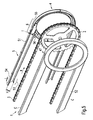
- FIG. 2 The schematic exploded view of Fig. 2 shows the structure of the pinion protection 4 and the Trummtikes. 5
- the pinion guard 4 comprises two annular shells 7, 8, which can be put together in the axial direction A, the one, inner, half shell 8 facing the frame, not shown, of a bicycle.
- the Fig. 2 has the half-shell 8 in the region of the chainstay of the bicycle (not shown) on an axial recess 9, in the region of the axial width B (see. Fig. 1 ) of the pinion protection 4 is reduced.
- a similar indentation may also be provided for the seat tube of the bicycle. Due to the indentation 9, the pinion protection 4 can also be mounted on drive pinions 2, which are only slightly spaced from the chain stay and / or the seat tube.
- the two half-shells 7, 8 are U-shaped or approximately U-shaped, the leg 8a assigned to the outer circumferential surface U being longer than the leg 8b assigned to the inner peripheral surface I.
- the one half shell in the embodiment of the Fig. 2 If this is, for example, the inner half-shell 8, may have a smaller outer diameter and be inserted into the other, outer, half-shell 7 and taken from this.
- a separating gap 10 may be provided at one point of the smaller half shell 8, which preferably extends in the radial direction R straight through the entire cross section of the half shell 8.
- the separating gap 10 is in the horizontal direction at the height of the axis 11 of the drive pinion 2.
- the separating gap 10 makes it possible to reduce the outer circumference of the smaller, half-shell 8 elastically, so that they biased into the larger half-shell. 7 can be used.
- the larger half-shell 7, like the smaller half-shell 8, has a U-shaped cross section with two legs 7a, 7b.
- a labyrinth seal in the form of two overlapping projections in the axial direction, which together should not exceed the wall thickness of the half-shell 8 in the axial direction, may be formed on the separating gap 10.
- the separating gap 10 may also be attached to the larger half-shell 7.
- each of the half shells 7, 8 each with a lateral, annular and axially facing side protection wall 12, 13 and with a projecting in the axial direction of the drive pinion 2, circular segment-shaped Chain protection wall 14, 15 provided.
- the chain protection walls 14, 15 overlap each other in the radial direction and thus form a large-scale labyrinth seal for the interior through which hardly any contamination can penetrate.
- the chain guard wall 14 of the smaller half-shell is located on a diameter 16 which is smaller than the diameter on which the likewise circular segment-shaped outer chain guard wall 15 of the larger half-shell is located.
- the outer chain guard wall 15 forms the peripheral surface U.
- the two chain protection walls 14, 15 each end in recesses 18, 19 for the upper and lower protection against trush 5.
- the recesses 18, 19 are preferably at the position of the half-shells 7, 8, extending in the axial direction A with the area 20th overlaps, in which the chain 3 runs on the drive pinion 2.
- the recesses 18, 19 Viewed in the direction of the chain K, the recesses 18, 19 have a substantially rectangular contour, which is designed to be complementary to the outer contour of the respective trunk protection 5 in the direction of the chain K.
- the region 21, which is not wrapped by the chain 3, is assigned a tooth protection wall 22, 23 in both half shells 7, 8, which projects from the side protection walls 12, 13 of the half shells 7, 8 in the form of a circle segment in the axial direction towards the drive pinion 2.
- the tooth protection walls 22, 23 are at the same diameters 16, 17 as the respective chain protection walls 14, 15.
- the tooth protection wall 22 of the half-shell 8 on a larger diameter and the protective wall 23 of the other half-shell 7 on a larger diameter lie, so that once the half-shell 7 and once the half-shell 8 forms a part of the outer peripheral surface U of the assembled pinion protection 4.
- the tooth protection walls 22, 23 overlap in the radial direction R to form a labyrinth seal.
- an annular, in the axial direction of the side shield 12 to the drive pinion 2 projecting towards sealing lip 24 is arranged whose length in the axial direction A is smaller than that of the chain protection wall 14.
- the sealing lip 24 seals the interior of the Pinion protection 4 against the side surface 25 of the drive pinion 2 from.
- the axial end of the sealing lip 24 tapers in cross-section towards the drive pinion 2, preferably in the form of a point, in order to avoid the setting of soiling.
- the bicycle facing, inner half-shell 8 also has a sealing lip 26 which is formed according to the sealing lip 24 of the outer half-shell 7.
- the height of the sealing lip 26 is correspondingly reduced or is no longer present, so that a flat, always equal to the drive pinion 2 spaced seal arises.
- the chain protection walls 14, 15 and the tooth protection walls 22, 23 are formed by the long legs 7a, 8a, the sealing lips 24, 26 of the short legs 7b, 8b of the U-shaped cross sections of the half-shells 7, 8.
- composite pinion protection 4 forms between the opposing sealing lips 24, 26 an annular gap whose width in the axial direction is greater than the width of the drive pinion 2 in the axial direction and smaller than the width of the chain 3 in the axial direction.
- the opposing axially facing inner surfaces of the half-shells 7, 8 have a distance which is greater than the width of the chain third
- the half-shells 7, 8 For stiffening and better floating mounting of the half-shells 7, 8, these can be provided in the region 12 with a between the chain protection wall 14, 15 and the sealing lip 24, 26, axially projecting and segmentally extending guide and stiffening web 27.
- the web 27 may be interrupted in the region of the recesses 18, 19 and extend on the other side of the recesses again in a circle segment shape, in order to stiffen the half shells 7, 8 here as well.
- pivot pin 28 is provided in the region of the recesses 18, 19 still axially projecting to the drive pin 2 pivot pin 28 in the region of the recesses 18, 19 still axially projecting to the drive pin 2 pivot pin 28 in the region of the recesses 18, 19 still axially projecting to the drive pin 2 pivot pin 28 in the region of the recesses 18, 19 still axially projecting to the drive pin 2 pivot pin 28 is provided.
- the height of the pivot pin preferably does not exceed the height of the stiffening web 27.
- the anti-fall protection 5 is also constructed from two axially assembled half-shells 30, 31, each having a U-shaped cross-section.
- the one half-shell 31 can be inserted into the other half-shell 30.
- the upper and lower Trummschutz 5 are constructed identically, the lower anti-trap is installed only once in its longitudinal direction rotated by 180 °.
- d. H. in the chain direction K to prevent form-fitting elements 32, 33 are provided, which are in composite tripod 5 are engaged with each other and the two half-shells 30, 31 engage in the longitudinal direction.
- the half-shells 7, 8 overlap in the direction in which the chain 3 is deflectable.
- the nested half shells 30, 31 overlap in the region of their cross-sectional legs.
- the wall thickness of the Trummtikes 5 in the axial direction should preferably at most equal to the height of the pins 28, so that the interior of the Trummtikes without Cross-section jump and without protruding into the interior projections in the interior of the pinion protection 4 passes.
- the wall thickness of the pinion protection 4 in the region of the recesses 18, 19 and the wall thickness at the end 33 of the anti-fall protection 5 is reduced so that together the original wall thickness of the pinion protection 4 or protection 5 results.
- the axially facing surfaces of the receptacles 18, 19 inside and the ends 33 are set back outside in the transition region 6.
- the other end 36 of the Trummschutzes 5 is free and can be shortened by the user to any length.
- Fig. 3 shows a schematic side view of a chain guard 1, which is on a drive pinion 2 and a chain 3, which is shown in sections only by its center line, self-holding, ie without attachment to the bicycle frame, floating, ie with play, and self-centering. Furthermore, in Fig. 3 schematically illustrated a derailleur 40 with a sprocket 41 and a rear derailleur 42.
- the course of the chain 3 via the largest gear 44 of the sprocket assembly 41 is shown.
- the reference numeral 45 is used for the course of the chain 3 over the smallest sprocket 46.
- the different position of the switching mechanism 42 is also shown for the two different chain progressions 43, 45.
- the course 43, 45 of the chain changes away from the drive sprocket 2 as a function of which sprocket of the sprocket set the chain 3 is running over. If it runs over the largest sprocket 44, then its course 43 is deflected upwards relative to the path via the smallest sprocket 46 on the upper and lower sprockets. In this case, the chain 3 always runs straight between the point 20 of the drive pinion 2 and the casserole point on the respective sprocket of the sprocket assembly 41. It only changes the angle at which the chain 3 to the drive sprocket 2 runs.
- the chain guard 1 is therefore provided with a movement zone 47 whose deflectability relative to the deflectability of the anti-fall protection 5 is increased.
- the protection against loss 5 can follow the course of the chain in a straight line without deformation, which reduces the frictional forces.
- the movement between Trummschutz 5 and 4 pinion protection is compensated almost exclusively in the movement zone 47.
- the movement zone 47 overlaps in the axial direction with the region 20 (see. Fig. 2 ) and can be realized by a joint, in particular the articulated connection 28, 35.
- connection between the pinion protection 4 and the anti-fall protection 5 has no spring elements and allows a relative movement of the anti-fall protection and the sprocket protection almost without elastic deformations, so that no restoring forces occur during the relative movement.
- the movement of the chain 3 takes place not only in the plane of the drive pinion 2, but also in a direction perpendicular thereto, such as Fig. 4 shows. Since the sprockets of the sprocket set 41 are staggered in the axial direction A, the antivibration 5 must also follow a movement of the chain in the axial direction. This is achieved in that the deflectability is also concentrated in the axial direction in the movement zone 47. The pinion protection 4 remains undeformed, while the anti-fall protection 5, also undeformed, follows the movements of the chain. The compensation of the relative movement takes place exclusively in the movement zone 47.
- the half-shell 30 of the at least one anti-curl (see. FIG. 2 ) and the half-shell 7 of the pinion protection are integrated into a common, one-piece half-shell 50. Accordingly, the half-shells 31 and 8 are combined in a single half-shell 51.
- the half shells 50, 51 are, as in the previous embodiment, assembled in the axial direction.
- the movement zone 47 or the transition region 6 can be made of a plastic, which is softer or more flexible and thus easier to deflect than the plastic used for the pinion protection 4.
- the Shore hardness in the transition region can be about 70 to 80 Shore A, while the Shore hardness of the pinion protection is about 30 to 40 Shore D.
- the entire anti-fall protection can be made of the material of the transition region 6.
- the antivibration device 5 can form an inlet region 53 which widens in the direction away from the sprocket protection 4.
- the length L of the inlet region is approximately one to two times measured in the plane of the drive pinion 2 clear height of the inlet region 53.
- From the point 54 of the lowest clear height of Trummtikes 5 extends the clear height back to the pinion protection 2.
- the clear height T in the transition region of the anti-fall protection 5 corresponds approximately to the clear height H. It can in particular about two to ten millimeters, preferably be about seven to nine millimeters larger than the clear height at the narrowest point 54.
- the two upper sides C of the anti-fall protection preferably run parallel to each other except for the inlet region 53, so that the taper between the narrowest point 54 and the transitional region 6 is reflected in an obliquely directed course of the mutually facing sides of the anti-fall protection 5.
- the anti-fall protection 5 and the pinion protection 4 can also be made of a uniform material.
Landscapes
- Engineering & Computer Science (AREA)
- Mechanical Engineering (AREA)
- Devices For Conveying Motion By Means Of Endless Flexible Members (AREA)
- Professional, Industrial, Or Sporting Protective Garments (AREA)
Applications Claiming Priority (1)
| Application Number | Priority Date | Filing Date | Title |
|---|---|---|---|
| DE200710028271 DE102007028271A1 (de) | 2007-06-15 | 2007-06-15 | Flexibler Kettenschutz |
Publications (3)
| Publication Number | Publication Date |
|---|---|
| EP2003048A2 true EP2003048A2 (fr) | 2008-12-17 |
| EP2003048A3 EP2003048A3 (fr) | 2010-10-13 |
| EP2003048B1 EP2003048B1 (fr) | 2013-02-20 |
Family
ID=39773199
Family Applications (1)
| Application Number | Title | Priority Date | Filing Date |
|---|---|---|---|
| EP20080003994 Active EP2003048B1 (fr) | 2007-06-15 | 2008-03-04 | Protection de chaîne flexible |
Country Status (2)
| Country | Link |
|---|---|
| EP (1) | EP2003048B1 (fr) |
| DE (1) | DE102007028271A1 (fr) |
Cited By (2)
| Publication number | Priority date | Publication date | Assignee | Title |
|---|---|---|---|---|
| WO2014148899A1 (fr) * | 2013-03-20 | 2014-09-25 | Carlier Group B.V. | Garde-chaîne et procédé associé |
| WO2019203649A1 (fr) * | 2018-04-18 | 2019-10-24 | Infento Property B.V. | Dispositif de protection de chaîne cinématique |
Families Citing this family (2)
| Publication number | Priority date | Publication date | Assignee | Title |
|---|---|---|---|---|
| US12522318B2 (en) * | 2021-12-31 | 2026-01-13 | Zwift, Inc. | Single-sprocket system for a bicycle trainer |
| DE202024102352U1 (de) * | 2024-05-07 | 2024-06-04 | Kalkhoff Werke Gmbh | Kettenkasten für ein Fahrrad, insbesondere für ein zumindest hinterradgefedertes Fahrrad, und Fahrrad |
Citations (6)
| Publication number | Priority date | Publication date | Assignee | Title |
|---|---|---|---|---|
| DE93621C (fr) | ||||
| GB189704057A (en) | 1897-02-15 | 1898-02-12 | Norman Arter Phillips | Improvements in Gear Cases, particularly applicable for Use on Bicycles, Tricycles and similar Vehicles to Enclose and Protect the Gearing which Couples the Crank Shaft and Driving Wheel. |
| CH179633A (de) | 1934-11-21 | 1935-09-15 | Steiger Hermann | Kettenschutz für Fahrzeuge, insbesondere Fahrräder. |
| FR968995A (fr) | 1948-07-06 | 1950-12-11 | Sarl Heurtey & Cie | Procédé de gazéification de combustibles liquides et appareillage de mise en oeuvre de ce procédé |
| US4054063A (en) | 1975-09-08 | 1977-10-18 | Cycles Peugeot | Guard for a chain and chain wheel transmission in particular for the transmission of a cycle or the like |
| DE3629463A1 (de) | 1986-08-29 | 1988-03-10 | Guenther Saak | Kettenschutz, insbesondere fuer einspurfahrzeuge |
Family Cites Families (1)
| Publication number | Priority date | Publication date | Assignee | Title |
|---|---|---|---|---|
| DK1795440T3 (da) | 2004-08-06 | 2009-01-26 | Hebie Gmbh & Co Kg | Kædeafskærmning til afskærmning af drivkæden på en cykel |
-
2007
- 2007-06-15 DE DE200710028271 patent/DE102007028271A1/de not_active Withdrawn
-
2008
- 2008-03-04 EP EP20080003994 patent/EP2003048B1/fr active Active
Patent Citations (6)
| Publication number | Priority date | Publication date | Assignee | Title |
|---|---|---|---|---|
| DE93621C (fr) | ||||
| GB189704057A (en) | 1897-02-15 | 1898-02-12 | Norman Arter Phillips | Improvements in Gear Cases, particularly applicable for Use on Bicycles, Tricycles and similar Vehicles to Enclose and Protect the Gearing which Couples the Crank Shaft and Driving Wheel. |
| CH179633A (de) | 1934-11-21 | 1935-09-15 | Steiger Hermann | Kettenschutz für Fahrzeuge, insbesondere Fahrräder. |
| FR968995A (fr) | 1948-07-06 | 1950-12-11 | Sarl Heurtey & Cie | Procédé de gazéification de combustibles liquides et appareillage de mise en oeuvre de ce procédé |
| US4054063A (en) | 1975-09-08 | 1977-10-18 | Cycles Peugeot | Guard for a chain and chain wheel transmission in particular for the transmission of a cycle or the like |
| DE3629463A1 (de) | 1986-08-29 | 1988-03-10 | Guenther Saak | Kettenschutz, insbesondere fuer einspurfahrzeuge |
Cited By (3)
| Publication number | Priority date | Publication date | Assignee | Title |
|---|---|---|---|---|
| WO2014148899A1 (fr) * | 2013-03-20 | 2014-09-25 | Carlier Group B.V. | Garde-chaîne et procédé associé |
| WO2019203649A1 (fr) * | 2018-04-18 | 2019-10-24 | Infento Property B.V. | Dispositif de protection de chaîne cinématique |
| NL2020785B1 (en) * | 2018-04-18 | 2019-10-24 | Infento Property B V | Drivetrain guard |
Also Published As
| Publication number | Publication date |
|---|---|
| EP2003048B1 (fr) | 2013-02-20 |
| DE102007028271A1 (de) | 2008-12-18 |
| EP2003048A3 (fr) | 2010-10-13 |
Similar Documents
| Publication | Publication Date | Title |
|---|---|---|
| EP2684790B1 (fr) | Galet guide-chaîne pour un dérailleur arrière d'une chaîne de bicyclette et dérailleur arrière doté d'un tel galet guide-chaîne | |
| EP0995938B1 (fr) | Joint d'étancheite pour raccord enfichable | |
| DE69104865T2 (de) | Zusammenbau eines mehrstufigen Kettenrades für ein Fahrrad. | |
| EP1521893B1 (fr) | Fermeture comportant deux tiges de verrouillage, notamment pour des vehicules | |
| EP0582095A1 (fr) | Dispositif de fixation en matière plastique | |
| DE60105680T2 (de) | Rolle für Kette und mit der Rolle versehene Kette | |
| WO2011160153A1 (fr) | Engrenage | |
| EP2235398B1 (fr) | Roue hélicoïdale à amortissement | |
| EP2003048B1 (fr) | Protection de chaîne flexible | |
| DE2835551C2 (de) | Schmutzabweiser für einen Gewindebetrieb, insbesondere Eisbrecher für einen Kugelgewindetrieb | |
| DE19546906A1 (de) | Wischerlager für eine Scheibenwischvorrichtung, insbesondere eines Kraftfahrzeuges | |
| DE202016105233U1 (de) | Fahrradfrontumwerfer | |
| DE3518798A1 (de) | Umwerfer fuer ein fahrrad | |
| DE10220879A1 (de) | Ständer zum Aufspannen von stabförmigen Teilen | |
| DE2657905A1 (de) | Verbindung zwischen den kettengliedern einer gleiskette | |
| DE69111356T2 (de) | Treibkette. | |
| EP1818240B1 (fr) | Plaque d'appui pour un mécanisme de direction | |
| EP0916569B1 (fr) | Garde-boue pour un véhicule automobile, spécialement pour un camion | |
| DE69210981T2 (de) | Schalthebellagerung | |
| DE102006021862A1 (de) | Gelenkanordnung für ein Fahrzeug | |
| DE60313504T2 (de) | Seitliche halteeinrichtung für personenförderband | |
| DE102008023635B4 (de) | Tülle | |
| DE102014019818B4 (de) | Fahrradkettenrad | |
| EP0004067A1 (fr) | Support d'enroulement de fil à éléments porteurs en forme de barreaux s'étendant parallèlement à son axe | |
| EP1488885A2 (fr) | Tablier de protection, en particulier pour machines-outils |
Legal Events
| Date | Code | Title | Description |
|---|---|---|---|
| PUAI | Public reference made under article 153(3) epc to a published international application that has entered the european phase |
Free format text: ORIGINAL CODE: 0009012 |
|
| AK | Designated contracting states |
Kind code of ref document: A2 Designated state(s): AT BE BG CH CY CZ DE DK EE ES FI FR GB GR HR HU IE IS IT LI LT LU LV MC MT NL NO PL PT RO SE SI SK TR |
|
| AX | Request for extension of the european patent |
Extension state: AL BA MK RS |
|
| PUAL | Search report despatched |
Free format text: ORIGINAL CODE: 0009013 |
|
| AK | Designated contracting states |
Kind code of ref document: A3 Designated state(s): AT BE BG CH CY CZ DE DK EE ES FI FR GB GR HR HU IE IS IT LI LT LU LV MC MT NL NO PL PT RO SE SI SK TR |
|
| AX | Request for extension of the european patent |
Extension state: AL BA MK RS |
|
| 17P | Request for examination filed |
Effective date: 20110221 |
|
| AKX | Designation fees paid |
Designated state(s): AT BE BG CH CY CZ DE DK EE ES FI FR GB GR HR HU IE IS IT LI LT LU LV MC MT NL NO PL PT RO SE SI SK TR |
|
| GRAP | Despatch of communication of intention to grant a patent |
Free format text: ORIGINAL CODE: EPIDOSNIGR1 |
|
| GRAS | Grant fee paid |
Free format text: ORIGINAL CODE: EPIDOSNIGR3 |
|
| GRAA | (expected) grant |
Free format text: ORIGINAL CODE: 0009210 |
|
| AK | Designated contracting states |
Kind code of ref document: B1 Designated state(s): AT BE BG CH CY CZ DE DK EE ES FI FR GB GR HR HU IE IS IT LI LT LU LV MC MT NL NO PL PT RO SE SI SK TR |
|
| REG | Reference to a national code |
Ref country code: GB Ref legal event code: FG4D Free format text: NOT ENGLISH |
|
| REG | Reference to a national code |
Ref country code: CH Ref legal event code: EP |
|
| REG | Reference to a national code |
Ref country code: AT Ref legal event code: REF Ref document number: 597413 Country of ref document: AT Kind code of ref document: T Effective date: 20130315 |
|
| REG | Reference to a national code |
Ref country code: IE Ref legal event code: FG4D Free format text: LANGUAGE OF EP DOCUMENT: GERMAN |
|
| REG | Reference to a national code |
Ref country code: DE Ref legal event code: R096 Ref document number: 502008009250 Country of ref document: DE Effective date: 20130418 |
|
| REG | Reference to a national code |
Ref country code: NL Ref legal event code: VDEP Effective date: 20130220 |
|
| REG | Reference to a national code |
Ref country code: LT Ref legal event code: MG4D |
|
| PG25 | Lapsed in a contracting state [announced via postgrant information from national office to epo] |
Ref country code: IS Free format text: LAPSE BECAUSE OF FAILURE TO SUBMIT A TRANSLATION OF THE DESCRIPTION OR TO PAY THE FEE WITHIN THE PRESCRIBED TIME-LIMIT Effective date: 20130620 Ref country code: SE Free format text: LAPSE BECAUSE OF FAILURE TO SUBMIT A TRANSLATION OF THE DESCRIPTION OR TO PAY THE FEE WITHIN THE PRESCRIBED TIME-LIMIT Effective date: 20130220 Ref country code: ES Free format text: LAPSE BECAUSE OF FAILURE TO SUBMIT A TRANSLATION OF THE DESCRIPTION OR TO PAY THE FEE WITHIN THE PRESCRIBED TIME-LIMIT Effective date: 20130531 Ref country code: BG Free format text: LAPSE BECAUSE OF FAILURE TO SUBMIT A TRANSLATION OF THE DESCRIPTION OR TO PAY THE FEE WITHIN THE PRESCRIBED TIME-LIMIT Effective date: 20130520 Ref country code: LT Free format text: LAPSE BECAUSE OF FAILURE TO SUBMIT A TRANSLATION OF THE DESCRIPTION OR TO PAY THE FEE WITHIN THE PRESCRIBED TIME-LIMIT Effective date: 20130220 Ref country code: NO Free format text: LAPSE BECAUSE OF FAILURE TO SUBMIT A TRANSLATION OF THE DESCRIPTION OR TO PAY THE FEE WITHIN THE PRESCRIBED TIME-LIMIT Effective date: 20130520 |
|
| PG25 | Lapsed in a contracting state [announced via postgrant information from national office to epo] |
Ref country code: GR Free format text: LAPSE BECAUSE OF FAILURE TO SUBMIT A TRANSLATION OF THE DESCRIPTION OR TO PAY THE FEE WITHIN THE PRESCRIBED TIME-LIMIT Effective date: 20130521 Ref country code: SI Free format text: LAPSE BECAUSE OF FAILURE TO SUBMIT A TRANSLATION OF THE DESCRIPTION OR TO PAY THE FEE WITHIN THE PRESCRIBED TIME-LIMIT Effective date: 20130220 Ref country code: FI Free format text: LAPSE BECAUSE OF FAILURE TO SUBMIT A TRANSLATION OF THE DESCRIPTION OR TO PAY THE FEE WITHIN THE PRESCRIBED TIME-LIMIT Effective date: 20130220 Ref country code: LV Free format text: LAPSE BECAUSE OF FAILURE TO SUBMIT A TRANSLATION OF THE DESCRIPTION OR TO PAY THE FEE WITHIN THE PRESCRIBED TIME-LIMIT Effective date: 20130220 Ref country code: PL Free format text: LAPSE BECAUSE OF FAILURE TO SUBMIT A TRANSLATION OF THE DESCRIPTION OR TO PAY THE FEE WITHIN THE PRESCRIBED TIME-LIMIT Effective date: 20130220 Ref country code: PT Free format text: LAPSE BECAUSE OF FAILURE TO SUBMIT A TRANSLATION OF THE DESCRIPTION OR TO PAY THE FEE WITHIN THE PRESCRIBED TIME-LIMIT Effective date: 20130620 |
|
| BERE | Be: lapsed |
Owner name: HEBIE G.M.B.H. & CO.KG Effective date: 20130331 |
|
| PG25 | Lapsed in a contracting state [announced via postgrant information from national office to epo] |
Ref country code: HR Free format text: LAPSE BECAUSE OF FAILURE TO SUBMIT A TRANSLATION OF THE DESCRIPTION OR TO PAY THE FEE WITHIN THE PRESCRIBED TIME-LIMIT Effective date: 20130220 |
|
| PG25 | Lapsed in a contracting state [announced via postgrant information from national office to epo] |
Ref country code: EE Free format text: LAPSE BECAUSE OF FAILURE TO SUBMIT A TRANSLATION OF THE DESCRIPTION OR TO PAY THE FEE WITHIN THE PRESCRIBED TIME-LIMIT Effective date: 20130220 Ref country code: MC Free format text: LAPSE BECAUSE OF NON-PAYMENT OF DUE FEES Effective date: 20130331 Ref country code: RO Free format text: LAPSE BECAUSE OF FAILURE TO SUBMIT A TRANSLATION OF THE DESCRIPTION OR TO PAY THE FEE WITHIN THE PRESCRIBED TIME-LIMIT Effective date: 20130220 Ref country code: DK Free format text: LAPSE BECAUSE OF FAILURE TO SUBMIT A TRANSLATION OF THE DESCRIPTION OR TO PAY THE FEE WITHIN THE PRESCRIBED TIME-LIMIT Effective date: 20130220 Ref country code: CZ Free format text: LAPSE BECAUSE OF FAILURE TO SUBMIT A TRANSLATION OF THE DESCRIPTION OR TO PAY THE FEE WITHIN THE PRESCRIBED TIME-LIMIT Effective date: 20130220 Ref country code: NL Free format text: LAPSE BECAUSE OF FAILURE TO SUBMIT A TRANSLATION OF THE DESCRIPTION OR TO PAY THE FEE WITHIN THE PRESCRIBED TIME-LIMIT Effective date: 20130220 Ref country code: SK Free format text: LAPSE BECAUSE OF FAILURE TO SUBMIT A TRANSLATION OF THE DESCRIPTION OR TO PAY THE FEE WITHIN THE PRESCRIBED TIME-LIMIT Effective date: 20130220 |
|
| REG | Reference to a national code |
Ref country code: CH Ref legal event code: PL |
|
| PG25 | Lapsed in a contracting state [announced via postgrant information from national office to epo] |
Ref country code: CY Free format text: LAPSE BECAUSE OF FAILURE TO SUBMIT A TRANSLATION OF THE DESCRIPTION OR TO PAY THE FEE WITHIN THE PRESCRIBED TIME-LIMIT Effective date: 20130220 |
|
| PLBE | No opposition filed within time limit |
Free format text: ORIGINAL CODE: 0009261 |
|
| STAA | Information on the status of an ep patent application or granted ep patent |
Free format text: STATUS: NO OPPOSITION FILED WITHIN TIME LIMIT |
|
| PG25 | Lapsed in a contracting state [announced via postgrant information from national office to epo] |
Ref country code: IT Free format text: LAPSE BECAUSE OF FAILURE TO SUBMIT A TRANSLATION OF THE DESCRIPTION OR TO PAY THE FEE WITHIN THE PRESCRIBED TIME-LIMIT Effective date: 20130220 |
|
| REG | Reference to a national code |
Ref country code: IE Ref legal event code: MM4A |
|
| 26N | No opposition filed |
Effective date: 20131121 |
|
| PG25 | Lapsed in a contracting state [announced via postgrant information from national office to epo] |
Ref country code: LI Free format text: LAPSE BECAUSE OF NON-PAYMENT OF DUE FEES Effective date: 20130331 Ref country code: IE Free format text: LAPSE BECAUSE OF NON-PAYMENT OF DUE FEES Effective date: 20130304 Ref country code: BE Free format text: LAPSE BECAUSE OF NON-PAYMENT OF DUE FEES Effective date: 20130331 Ref country code: CH Free format text: LAPSE BECAUSE OF NON-PAYMENT OF DUE FEES Effective date: 20130331 |
|
| REG | Reference to a national code |
Ref country code: DE Ref legal event code: R097 Ref document number: 502008009250 Country of ref document: DE Effective date: 20131121 |
|
| REG | Reference to a national code |
Ref country code: AT Ref legal event code: MM01 Ref document number: 597413 Country of ref document: AT Kind code of ref document: T Effective date: 20130304 |
|
| PG25 | Lapsed in a contracting state [announced via postgrant information from national office to epo] |
Ref country code: MT Free format text: LAPSE BECAUSE OF FAILURE TO SUBMIT A TRANSLATION OF THE DESCRIPTION OR TO PAY THE FEE WITHIN THE PRESCRIBED TIME-LIMIT Effective date: 20130220 |
|
| PG25 | Lapsed in a contracting state [announced via postgrant information from national office to epo] |
Ref country code: AT Free format text: LAPSE BECAUSE OF NON-PAYMENT OF DUE FEES Effective date: 20130304 |
|
| PG25 | Lapsed in a contracting state [announced via postgrant information from national office to epo] |
Ref country code: TR Free format text: LAPSE BECAUSE OF FAILURE TO SUBMIT A TRANSLATION OF THE DESCRIPTION OR TO PAY THE FEE WITHIN THE PRESCRIBED TIME-LIMIT Effective date: 20130220 |
|
| PG25 | Lapsed in a contracting state [announced via postgrant information from national office to epo] |
Ref country code: HU Free format text: LAPSE BECAUSE OF FAILURE TO SUBMIT A TRANSLATION OF THE DESCRIPTION OR TO PAY THE FEE WITHIN THE PRESCRIBED TIME-LIMIT; INVALID AB INITIO Effective date: 20080304 Ref country code: LU Free format text: LAPSE BECAUSE OF NON-PAYMENT OF DUE FEES Effective date: 20130304 |
|
| REG | Reference to a national code |
Ref country code: FR Ref legal event code: PLFP Year of fee payment: 9 |
|
| PGFP | Annual fee paid to national office [announced via postgrant information from national office to epo] |
Ref country code: GB Payment date: 20160321 Year of fee payment: 9 Ref country code: FR Payment date: 20160328 Year of fee payment: 9 |
|
| GBPC | Gb: european patent ceased through non-payment of renewal fee |
Effective date: 20170304 |
|
| REG | Reference to a national code |
Ref country code: FR Ref legal event code: ST Effective date: 20171130 |
|
| PG25 | Lapsed in a contracting state [announced via postgrant information from national office to epo] |
Ref country code: FR Free format text: LAPSE BECAUSE OF NON-PAYMENT OF DUE FEES Effective date: 20170331 |
|
| PG25 | Lapsed in a contracting state [announced via postgrant information from national office to epo] |
Ref country code: GB Free format text: LAPSE BECAUSE OF NON-PAYMENT OF DUE FEES Effective date: 20170304 |
|
| PGFP | Annual fee paid to national office [announced via postgrant information from national office to epo] |
Ref country code: DE Payment date: 20250327 Year of fee payment: 18 |