EP2003073A1 - Modularer Bootshaken für Abdeckelement - Google Patents
Modularer Bootshaken für Abdeckelement Download PDFInfo
- Publication number
- EP2003073A1 EP2003073A1 EP08356078A EP08356078A EP2003073A1 EP 2003073 A1 EP2003073 A1 EP 2003073A1 EP 08356078 A EP08356078 A EP 08356078A EP 08356078 A EP08356078 A EP 08356078A EP 2003073 A1 EP2003073 A1 EP 2003073A1
- Authority
- EP
- European Patent Office
- Prior art keywords
- modular
- pole
- bent portion
- gaff
- axis
- Prior art date
- Legal status (The legal status is an assumption and is not a legal conclusion. Google has not performed a legal analysis and makes no representation as to the accuracy of the status listed.)
- Granted
Links
Images
Classifications
-
- B—PERFORMING OPERATIONS; TRANSPORTING
- B65—CONVEYING; PACKING; STORING; HANDLING THIN OR FILAMENTARY MATERIAL
- B65D—CONTAINERS FOR STORAGE OR TRANSPORT OF ARTICLES OR MATERIALS, e.g. BAGS, BARRELS, BOTTLES, BOXES, CANS, CARTONS, CRATES, DRUMS, JARS, TANKS, HOPPERS, FORWARDING CONTAINERS; ACCESSORIES, CLOSURES, OR FITTINGS THEREFOR; PACKAGING ELEMENTS; PACKAGES
- B65D88/00—Large containers
- B65D88/02—Large containers rigid
- B65D88/12—Large containers rigid specially adapted for transport
- B65D88/122—Large containers rigid specially adapted for transport with access from above
- B65D88/124—Large containers rigid specially adapted for transport with access from above closable top
- B65D88/125—Large containers rigid specially adapted for transport with access from above closable top by flexible element, e.g. canvas
Definitions
- the present invention relates to a modular gaffe allowing the introduction or removal of a covering element over a bucket or a container or other space or surface to be covered.
- EP 1405804 The applicant holds a European patent granted EP 1405804 concerning a covering element which makes it possible to cover, for example, a bucket or container by means of a hook.
- the covering element described in the European patent granted EP 1405804 is made in a tarpaulin or net or protective fabric which is placed over a bucket or container or trailer transportable on or by a towing vehicle.
- the covering element comprises edges of greater length traversed by an elastic link making it possible to fold said edges on one of the faces of the covering element, at least one edge of shorter length cooperating with a traction tube comprising means folding device for storing the covering element and means for attaching the edges to the bucket or the container.
- the pulling tube of the covering element is designed to receive the branch of the hook gaff so as, on the one hand, to raise the covering element over the bucket or the container and, on the other hand, to move it to the above the bucket or container to cover it.
- the object of the present invention is to improve the gaff in its structure to improve its use by the user and thus facilitate movement of the covering element above the bucket or container or any other space or surface to cover.
- the modular gaffe according to the present invention consists of a boom comprising at one of its ends a bent portion, and a cooperating extension, depending on the use of the modular hook, either with the bent portion, or with the other free end of the pole lying opposite the bent part.
- the modular gaffe according to the present invention consists of a hook secured to the pole at the bent portion.
- the modular gaffe according to the present invention comprises a fixed pole at a distance from the bent portion of a stop which is constituted by a cylindrical tube or not disposed perpendicular to the axis of the pole.
- the modular gaffe according to the present invention comprises a pole which is integral with an immobilization axis for locking the tubular extension.
- the modular gaffe according to the present invention comprises a bent portion of the pole, integral with a stop, constituted by a peripheral flange welded around the tube forming said bent portion.
- the modular gaffe according to the present invention comprises a bent portion of the pole which is integral with a stop constituted by a cylindrical finger passing right through the diameter of the tube and extending beyond the latter.
- the modular gaffe according to the present invention consists of a tubular extension which comprises near its free end a peripheral collar.
- the modular gaffe according to the present invention consists of a tubular extension which comprises opposite the peripheral collar and at its other free end locking means having a bayonet-shaped profile or the like.
- the modular gaffe according to the present invention comprises locking means which are constituted by a bayonet-shaped cut or the like made directly in the thickness of the profile of the tubular extension.
- the modular gaffe according to the present invention consists of a hook which comprises at least one hooking part for fastening the elastic links of the covering element, said hooking parts being arranged in that at least one either in the same vertical plane passing through that of said bent portion of the pole to form, relative to the axis of said pole, hooking means directed in different directions.
- the modular gaffe according to the present invention consists of a hook which comprises at least one hooking part allowing the attachment of the elastic links of the covering element, said attachment portions being respectively arranged in separate and perpendicular planes two two to form, relative to the axis of the pole, hooking means directed in different directions.
- the modular gaffe according to the present invention consists of a hooking portion which is connected to the bent portion of the pole by a stop.
- the modular gaffe according to the present invention comprises a bent part comprising inside its bending radius a reinforcement.
- the modular gaffe according to the present invention comprises a stop which consists of a cylindrical axis integral with the pole and a wheel pivoting freely around the cylindrical axis.
- the modular gaffe according to the present invention comprises a wheel held laterally on the cylindrical axis by any fastening means removable or not.
- the modular gaffe according to the present invention comprises a wheel which is kept freely rotatable between the fixing means and a stop.
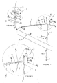
- the modular hook 1 consists of a pole 2 made in a hollow tube or not of cylindrical section or not made of alloy or composite and extending at one of its ends by a bent portion 3.
- the bent portion 3 is obtained by bending one of the ends of the pole 2 and can be arranged either in a direction perpendicular to that of the pole 2, or in a tilted direction without thereby changing the object of the present invention .
- the pole 2 is integral at a distance from the bent portion 3 of a stop 4 extending in a direction perpendicular to the axis XX 'of said pole to form a support coming, for example, against the rim of the bucket or container.
- the stop 4 consists of a cylindrical or non-cylindrical tube extending perpendicularly to the pole 2 and in the same plane as that containing the bent portion 3.
- the pole 2 is secured between its lower free end 11, located opposite the bent portion 3, and the stop 4 of an immobilization axis 5 passing right through the diameter or section of the tube forming said pole 2 and extending beyond the latter.
- the angled portion 3 of the rod 2 is secured, between its free end and the bending zone, with an abutment 6 is constituted by a peripheral flange 6 is welded around the tube forming the angled portion 3 of the pole 2 or by a cylindrical finger 6b passing through from one side to the diameter of the tube and extending beyond the latter.
- the pole 2 comprises at its bent portion 3 and opposite the latter a hook 8 extending in the extension of said pole and above said bent portion 3.
- the hook 8 is made, for example, from a solid metal rod which is deformed to form three separate hook portions 8 a, 8 b, 8 c.
- the bracket 8 includes a first vertical rod 8 of which is welded to the shaft 2 parallel to the axis XX 'of the latter so that the first engaging portion 8a is placed at and slightly above the portion bent 3 of the modular gaffe 1.
- the first hooking portion 8a has a U-shaped profile open at the top and each of the branches may extend vertically in a plane parallel to that containing the axis XX 'of the shaft 2.
- the vertical rod 8 of the hook 8 is provided opposite to the first hooking portion 8 has a second engaging portion 8 b obtained in the extension of said rod 8 d.
- the second attachment portion 8 b is composed of a horizontal finger or not extending perpendicularly to the axis XX 'and towards the outside of the shaft 2.
- One of the branches of the first hooking portion 8 has U-shaped extends above the angled portion 3 of the Modular gaff 1 by a second vertical shaft 8 including an upper free end terminates in the third part of hanging 8 c .
- the third engaging portion 8c is constituted by a part of the second vertical rod 8 e which is inclined at an angle ⁇ relative to the axis XX 'of the pole 2.
- the third engaging portion 8c is also directed in a lateral direction or on the side with respect to the pole 2.
- the hook 8 of the Modular gaff 1 has latching portions 8 a, 8 b, 8 c which are respectively arranged in two separate planes normal to both to constitute with respect to the axis XX 'of the perch 2 fastening means directed in different directions.
- the modular hook 1 comprises a tubular extension 9 of cylindrical section or not and cooperating according to the use of said hook either with the bent portion 3, or with the lower free end 11 of the pole 2.
- the tubular extension 9 has an inner diameter slightly greater than the outer one of the pole 2 and the bent portion 3 so as to fit around them.
- the tubular extension 9 comprises near one of its ends 9 c 9 has a peripheral flange forming a support and protection for the hands of the user.
- the tubular extension 9 comprises, opposite to the peripheral flange 9 and has at its other free end 9 d, locking means 9b having a profile in the form of bayonet or the like.
- the locking means 9b consist either of a cut made directly in the thickness of the profile of the tubular extension 9, or by a composite insert or not introduced inside the free end 9 d and extending slightly the tubular extension 9 and having a bayonet-shaped cutout or the like.
- each end of the hollow tube forming the pole 2 and the bent part 3, as well as the stop 4 can be closed by a protective cap 10.
- the modular gaffe 1 is used by the technician on the one hand to arrange or remove, for example, a covering element over a bucket or container as described in the European patent issued EP 1405804 belonging to the applicant and on the other hand to hang elastic ties or eyelets or other said covering element on the periphery of the bucket or container or unhook them.
- the technician uses the modular hook 1 for the introduction or removal of the covering element, the latter introduces the tubular extension 9 by the free end 9c around the bent portion 3 until that said free end bears against the abutment 6.
- tubular extension 9 extends the bent portion 3 of the modular hook 1 to form a sort of gallows for the manipulation of any covering element.
- the technician introduces the tubular extension 9 in the traction means of the covering element, until the latter abut against the flange 9a.
- the technician connects the pole 2 with the covering element by means of an elastic or other relationship which is hooked at the first and second engaging portion 8a, 8b of the hook 8.
- the technician can using the modular hook 1 lift and carry the covering element over the bucket or container. During this manipulation the technician can rest the pole 2 on the edge of the bucket or container via the stop 4.
- the technician positions the tubular extension 9 in a direction that is the opposite to that previously described so that its free end 9 d having the bayonet-shaped locking means 9b or other cooperates with the immobilization axis 5 passing through apart from the diameter of the tube forming said pole 2.
- tubular extension 9 is rotated a quarter turn around the axis XX 'of the pole 2 in order to lock the immobilization axis 5 in the bayonet-shaped locking means 9b of the said extension.
- the technician can raise the latter by placing his hands against and below the flange 9 has to perfectly maintain the modular gaff 1.
- the technician can, by means of the first or third attachment portion 8 a, 8 c of the hook 8, catch other elastic cords, the cover member to be able to hang them on retaining means integral with the bucket or the container or unhooking them to fix or remove the covering element.
- the installation of the extension 9 around the pole 2 is not mandatory, it depends on the height to which the technician must arrive to maneuver with the hook 8 the elastic links or any other part of annoying element the operation of the covering element.
- tubular extension 9 is intended more particularly to increase either the length of the pole 2 or the bent portion 3 of the modular hook 1.
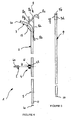
- the pole 2 comprises in a direction perpendicular to its axis XX 'a stop 4 and at its bent portion 3 a hook 8 extending above and in the extension of the said pole.
- the stop 4 differs from that described above in that it consists of a cylindrical axis 40 integral with the pole 2 and a wheel 41 pivoting freely around the cylindrical axis.
- the wheel 41 is held laterally on the cylindrical axis 40 by any fastening means removable or not.
- the wheel 41 comes, opposite the fastening means, bearing on a stop 43 for positioning the wheel 41 at a distance from the pole 2.
- the fixing means are for example made by deformation of the free end of the cylindrical axis 40 in order to keep the free wheel 41 rotated between this deformation and the abutment 43.
- the detachable fixing means are, for example, constituted by a cerclip 42 engaging in a groove formed at the free end of the cylindrical axis 40 in order to keep the free wheel 41 rotated between said cerclip 42 and the stop 43.
- the abutment 4 provided with its cylindrical axis 40 and its wheel 41 makes it possible to form a rolling support coming, for example, against the edge of the bucket or the container and facilitating the handling of the pole 2 by the technician carrying, through of the extension 9, the covering element.
- the hook 8 differs from that described above in that its angular position relative to the axis XX 'of the pole 2 is different so that the engaging portions 8 a, 8 b, 8 c are positioned in angled planes ensuring a better grip of the covering element and the use of the pole 2 by the technician.
- the hook 8 comprises a vertical rod 8 d which is welded to the pole 2 parallel to the axis XX 'of the latter.
- the vertical rod 8 comprises d below the angled portion 3 of the shaft 2 a hooking portion 8b obtained at the free end and in the extension of said rod 8 d.
- the connection portion 8b is constituted by a horizontal or non finger extending perpendicularly to the axis XX 'and towards the outside of the shaft 2.
- connection portion 8b of the vertical rod 8 engages over the angled portion 3 of the pole 2 with two other hooking portions 8 a, 8 c interconnected by a second rod 8 e right so as to be arranged in the same vertical plane passing through that of said bent portion 3.
- the engaging portion 8a is connected to the angled portion 3 of the shaft 2 by a stop 8 g serving firstly to enhance the stability of the hook 8 in relation to the shaft 2 and, secondly, of prevent the elastic links of the covering element are jammed at the junction of the straight rods 8 d and 8 e .
- the engaging portion 8a is positioned so that its open portion is directed upwardly, i.e., in a direction being opposite to the angled portion 3 of the shaft 2.
- connection portion 8b is positioned in a direction reverse to that of the engaging portion 8a that is to say that its open portion is directed above and toward the right rod 8d.
- bent portion 3 of the pole 2 comprises a reinforcement 15 disposed inside the bending radius so as to reinforce the latter when it supports the weight of the covering element by means of the extension 9.
- extension 9 is secured at one of its ends with a reinforced sleeve 9 f provided with locking means 9 in form b, for example, bayonet, in order to ensure its assembly around the pole 2 and his immobilization via the immobilization axis 5 as previously described.
Landscapes
- Engineering & Computer Science (AREA)
- Mechanical Engineering (AREA)
- Details Of Rigid Or Semi-Rigid Containers (AREA)
- Led Devices (AREA)
- Crystals, And After-Treatments Of Crystals (AREA)
- Helmets And Other Head Coverings (AREA)
- Connector Housings Or Holding Contact Members (AREA)
- Respiratory Apparatuses And Protective Means (AREA)
- Catching Or Destruction (AREA)
- Materials For Medical Uses (AREA)
- Supports Or Holders For Household Use (AREA)
- Fuses (AREA)
Priority Applications (2)
| Application Number | Priority Date | Filing Date | Title |
|---|---|---|---|
| PL08356078T PL2003073T3 (pl) | 2007-06-13 | 2008-06-05 | Bosak modułowy dla elementu przykrywającego |
| EP11162934.1A EP2341014B1 (de) | 2007-06-13 | 2008-06-05 | Modularer Bootshaken für Abdeckelement |
Applications Claiming Priority (1)
| Application Number | Priority Date | Filing Date | Title |
|---|---|---|---|
| FR0704183A FR2917320B1 (fr) | 2007-06-13 | 2007-06-13 | Gaffe modulaire pour element couvrant. |
Related Child Applications (1)
| Application Number | Title | Priority Date | Filing Date |
|---|---|---|---|
| EP11162934.1 Division-Into | 2011-04-19 |
Publications (3)
| Publication Number | Publication Date |
|---|---|
| EP2003073A1 true EP2003073A1 (de) | 2008-12-17 |
| EP2003073B1 EP2003073B1 (de) | 2011-08-03 |
| EP2003073B9 EP2003073B9 (de) | 2012-02-29 |
Family
ID=38961977
Family Applications (2)
| Application Number | Title | Priority Date | Filing Date |
|---|---|---|---|
| EP11162934.1A Active EP2341014B1 (de) | 2007-06-13 | 2008-06-05 | Modularer Bootshaken für Abdeckelement |
| EP08356078A Active EP2003073B9 (de) | 2007-06-13 | 2008-06-05 | Modularer Bootshaken für Abdeckelement |
Family Applications Before (1)
| Application Number | Title | Priority Date | Filing Date |
|---|---|---|---|
| EP11162934.1A Active EP2341014B1 (de) | 2007-06-13 | 2008-06-05 | Modularer Bootshaken für Abdeckelement |
Country Status (7)
| Country | Link |
|---|---|
| EP (2) | EP2341014B1 (de) |
| AT (1) | ATE518788T1 (de) |
| DK (1) | DK2003073T3 (de) |
| ES (2) | ES2369211T3 (de) |
| FR (1) | FR2917320B1 (de) |
| PL (1) | PL2003073T3 (de) |
| PT (1) | PT2003073E (de) |
Cited By (1)
| Publication number | Priority date | Publication date | Assignee | Title |
|---|---|---|---|---|
| EP2644535A1 (de) | 2012-03-27 | 2013-10-02 | H2Dx | Abdeckelement und Behälter mit einem solchen Abdeckelement |
Families Citing this family (1)
| Publication number | Priority date | Publication date | Assignee | Title |
|---|---|---|---|---|
| FR3154714B1 (fr) | 2023-10-31 | 2025-11-14 | H2Dx | Gaffe modulaire dont l’impact carbone est réduit |
Citations (2)
| Publication number | Priority date | Publication date | Assignee | Title |
|---|---|---|---|---|
| US3936088A (en) * | 1974-07-01 | 1976-02-03 | Charles Samuel Williams | Flexible tarpaulin handling device |
| EP1405804A1 (de) | 2002-10-04 | 2004-04-07 | Plantefort Expansion Sarl | Abdeckungselement für Behälter oder dergleichen |
Family Cites Families (1)
| Publication number | Priority date | Publication date | Assignee | Title |
|---|---|---|---|---|
| US3977719A (en) * | 1975-04-28 | 1976-08-31 | Thurston Howard E | Apparatus for covering open-bodied vehicles |
-
2007
- 2007-06-13 FR FR0704183A patent/FR2917320B1/fr not_active Expired - Fee Related
-
2008
- 2008-06-05 DK DK08356078.9T patent/DK2003073T3/da active
- 2008-06-05 PT PT08356078T patent/PT2003073E/pt unknown
- 2008-06-05 PL PL08356078T patent/PL2003073T3/pl unknown
- 2008-06-05 AT AT08356078T patent/ATE518788T1/de active
- 2008-06-05 ES ES08356078T patent/ES2369211T3/es active Active
- 2008-06-05 EP EP11162934.1A patent/EP2341014B1/de active Active
- 2008-06-05 EP EP08356078A patent/EP2003073B9/de active Active
- 2008-06-05 ES ES11162934T patent/ES2429501T3/es active Active
Patent Citations (2)
| Publication number | Priority date | Publication date | Assignee | Title |
|---|---|---|---|---|
| US3936088A (en) * | 1974-07-01 | 1976-02-03 | Charles Samuel Williams | Flexible tarpaulin handling device |
| EP1405804A1 (de) | 2002-10-04 | 2004-04-07 | Plantefort Expansion Sarl | Abdeckungselement für Behälter oder dergleichen |
Cited By (1)
| Publication number | Priority date | Publication date | Assignee | Title |
|---|---|---|---|---|
| EP2644535A1 (de) | 2012-03-27 | 2013-10-02 | H2Dx | Abdeckelement und Behälter mit einem solchen Abdeckelement |
Also Published As
| Publication number | Publication date |
|---|---|
| DK2003073T3 (da) | 2011-10-24 |
| EP2341014B1 (de) | 2013-08-21 |
| FR2917320B1 (fr) | 2009-09-04 |
| PL2003073T3 (pl) | 2011-11-30 |
| EP2003073B9 (de) | 2012-02-29 |
| ES2429501T3 (es) | 2013-11-15 |
| ES2369211T3 (es) | 2011-11-28 |
| EP2003073B1 (de) | 2011-08-03 |
| PT2003073E (pt) | 2011-10-11 |
| EP2341014A1 (de) | 2011-07-06 |
| ATE518788T1 (de) | 2011-08-15 |
| FR2917320A1 (fr) | 2008-12-19 |
Similar Documents
| Publication | Publication Date | Title |
|---|---|---|
| FR2635136A3 (fr) | Abri de protection solaire | |
| FR2556325A1 (fr) | Cage transporteuse pour manutention aerienne | |
| EP2738345A1 (de) | Trittleiter mit klappbarer Plattform und klappbaren Holmen | |
| EP2003073B9 (de) | Modularer Bootshaken für Abdeckelement | |
| EP2599938B1 (de) | Sicherheitssteg mit ausziehbarer Stützstrebe für Schalwand | |
| FR3059656B1 (fr) | Agencement de deroulement du cable enroule sur un touret | |
| FR2654642A1 (fr) | Sac pour clubs de golf a sangle bretelle de transport. | |
| EP1405804B1 (de) | Abdeckungselement für Behälter oder dergleichen | |
| FR2986218A1 (fr) | Systeme de prehension et de levage d'un conteneur de collecte des dechets et de commande d'ouverture/fermeture des trappes de vidage dudit conteneur | |
| FR2893228A1 (fr) | Dispositif de suspension pour cage de conchyliculture presentant au moins un element formant poignee. | |
| WO1985000328A1 (fr) | Essuie-glace comportant un axe d'articulation du balai sur le bras a verrouillage transversal | |
| FR3161622A1 (fr) | Dispositif d’assistance à la mise en place d’une sangle d’arrimage de chargement sur le plateau d’un véhicule de transport | |
| FR2781201A1 (fr) | Dispositif pour la suspension d'un recipient tel qu'un pot horticole | |
| WO2002032710A1 (fr) | Dispositif demontable et transportable pour l"enroulement et le deroulement d"un element couvrant de protection au-dessus d"une benne ou conteneur | |
| FR2983187A3 (fr) | Tete de fixation de cric de levage | |
| FR2589830A1 (fr) | Sangle pour chariots de transport de marchandises | |
| FR3085973A1 (fr) | Attache de liaison entre une pince a linge et un cadre de sechoir, ainsi que sechoir comportant de telles attaches | |
| FR2879177A1 (fr) | Corbeille de collecte des dechets | |
| FR2839025A1 (fr) | Dispositif manuel et demontable de deploiement de bache pour conteneur | |
| FR2990988A1 (fr) | Dispositif de stabilisation d'une echelle par des jambes telescopiques | |
| FR2962012A3 (fr) | Sac pour chariot de supermarche et ensemble le comprenant . | |
| WO1984002503A1 (fr) | Chariot pour transporter une planche a voile | |
| BE882613A (fr) | Dispositif de support d'un panneau de signalisation routiere ou analogue | |
| FR2902126A1 (fr) | Bracon d'etai pour banche ou analogue et banche munie d'un tel bracon | |
| EP3587224A1 (de) | Befestigungsvorrichtung eines reserverads eines kraftfahrzeugs |
Legal Events
| Date | Code | Title | Description |
|---|---|---|---|
| PUAI | Public reference made under article 153(3) epc to a published international application that has entered the european phase |
Free format text: ORIGINAL CODE: 0009012 |
|
| AK | Designated contracting states |
Kind code of ref document: A1 Designated state(s): AT BE BG CH CY CZ DE DK EE ES FI FR GB GR HR HU IE IS IT LI LT LU LV MC MT NL NO PL PT RO SE SI SK TR |
|
| AX | Request for extension of the european patent |
Extension state: AL BA MK RS |
|
| 17P | Request for examination filed |
Effective date: 20090612 |
|
| AKX | Designation fees paid |
Designated state(s): AT BE BG CH CY CZ DE DK EE ES FI FR GB GR HR HU IE IS IT LI LT LU LV MC MT NL NO PL PT RO SE SI SK TR |
|
| GRAP | Despatch of communication of intention to grant a patent |
Free format text: ORIGINAL CODE: EPIDOSNIGR1 |
|
| GRAS | Grant fee paid |
Free format text: ORIGINAL CODE: EPIDOSNIGR3 |
|
| GRAA | (expected) grant |
Free format text: ORIGINAL CODE: 0009210 |
|
| AK | Designated contracting states |
Kind code of ref document: B1 Designated state(s): AT BE BG CH CY CZ DE DK EE ES FI FR GB GR HR HU IE IS IT LI LT LU LV MC MT NL NO PL PT RO SE SI SK TR |
|
| REG | Reference to a national code |
Ref country code: GB Ref legal event code: FG4D Free format text: NOT ENGLISH |
|
| REG | Reference to a national code |
Ref country code: CH Ref legal event code: EP |
|
| REG | Reference to a national code |
Ref country code: IE Ref legal event code: FG4D Free format text: LANGUAGE OF EP DOCUMENT: FRENCH |
|
| REG | Reference to a national code |
Ref country code: DE Ref legal event code: R096 Ref document number: 602008008603 Country of ref document: DE Effective date: 20110929 |
|
| REG | Reference to a national code |
Ref country code: PT Ref legal event code: SC4A Free format text: AVAILABILITY OF NATIONAL TRANSLATION Effective date: 20110929 |
|
| REG | Reference to a national code |
Ref country code: NL Ref legal event code: T3 |
|
| REG | Reference to a national code |
Ref country code: DK Ref legal event code: T3 |
|
| REG | Reference to a national code |
Ref country code: SE Ref legal event code: TRGR |
|
| REG | Reference to a national code |
Ref country code: NO Ref legal event code: T2 Effective date: 20110803 Ref country code: ES Ref legal event code: FG2A Ref document number: 2369211 Country of ref document: ES Kind code of ref document: T3 Effective date: 20111128 |
|
| REG | Reference to a national code |
Ref country code: PL Ref legal event code: T3 |
|
| REG | Reference to a national code |
Ref country code: SK Ref legal event code: T3 Ref document number: E 10072 Country of ref document: SK |
|
| LTIE | Lt: invalidation of european patent or patent extension |
Effective date: 20110803 |
|
| PG25 | Lapsed in a contracting state [announced via postgrant information from national office to epo] |
Ref country code: LT Free format text: LAPSE BECAUSE OF FAILURE TO SUBMIT A TRANSLATION OF THE DESCRIPTION OR TO PAY THE FEE WITHIN THE PRESCRIBED TIME-LIMIT Effective date: 20110803 Ref country code: HR Free format text: LAPSE BECAUSE OF FAILURE TO SUBMIT A TRANSLATION OF THE DESCRIPTION OR TO PAY THE FEE WITHIN THE PRESCRIBED TIME-LIMIT Effective date: 20110803 Ref country code: IS Free format text: LAPSE BECAUSE OF FAILURE TO SUBMIT A TRANSLATION OF THE DESCRIPTION OR TO PAY THE FEE WITHIN THE PRESCRIBED TIME-LIMIT Effective date: 20111203 |
|
| REG | Reference to a national code |
Ref country code: NL Ref legal event code: SD Effective date: 20120203 Ref country code: CH Ref legal event code: PFUS Owner name: H2DX, FR Free format text: FORMER OWNER: PLANTEFORT EXPANSION, FR |
|
| PG25 | Lapsed in a contracting state [announced via postgrant information from national office to epo] |
Ref country code: SI Free format text: LAPSE BECAUSE OF FAILURE TO SUBMIT A TRANSLATION OF THE DESCRIPTION OR TO PAY THE FEE WITHIN THE PRESCRIBED TIME-LIMIT Effective date: 20110803 Ref country code: CY Free format text: LAPSE BECAUSE OF FAILURE TO SUBMIT A TRANSLATION OF THE DESCRIPTION OR TO PAY THE FEE WITHIN THE PRESCRIBED TIME-LIMIT Effective date: 20110803 Ref country code: LV Free format text: LAPSE BECAUSE OF FAILURE TO SUBMIT A TRANSLATION OF THE DESCRIPTION OR TO PAY THE FEE WITHIN THE PRESCRIBED TIME-LIMIT Effective date: 20110803 Ref country code: GR Free format text: LAPSE BECAUSE OF FAILURE TO SUBMIT A TRANSLATION OF THE DESCRIPTION OR TO PAY THE FEE WITHIN THE PRESCRIBED TIME-LIMIT Effective date: 20111104 |
|
| REG | Reference to a national code |
Ref country code: FR Ref legal event code: TP Owner name: H2DX, FR Effective date: 20120131 |
|
| REG | Reference to a national code |
Ref country code: DE Ref legal event code: R081 Ref document number: 602008008603 Country of ref document: DE Owner name: H2DX, FR Free format text: FORMER OWNER: PLANTEFORT EXPANSION, VAULX EN VELIN, FR Effective date: 20120229 |
|
| PG25 | Lapsed in a contracting state [announced via postgrant information from national office to epo] |
Ref country code: CZ Free format text: LAPSE BECAUSE OF FAILURE TO SUBMIT A TRANSLATION OF THE DESCRIPTION OR TO PAY THE FEE WITHIN THE PRESCRIBED TIME-LIMIT Effective date: 20110803 |
|
| REG | Reference to a national code |
Ref country code: HU Ref legal event code: AG4A Ref document number: E012500 Country of ref document: HU |
|
| PG25 | Lapsed in a contracting state [announced via postgrant information from national office to epo] |
Ref country code: EE Free format text: LAPSE BECAUSE OF FAILURE TO SUBMIT A TRANSLATION OF THE DESCRIPTION OR TO PAY THE FEE WITHIN THE PRESCRIBED TIME-LIMIT Effective date: 20110803 Ref country code: RO Free format text: LAPSE BECAUSE OF FAILURE TO SUBMIT A TRANSLATION OF THE DESCRIPTION OR TO PAY THE FEE WITHIN THE PRESCRIBED TIME-LIMIT Effective date: 20110803 |
|
| PLBE | No opposition filed within time limit |
Free format text: ORIGINAL CODE: 0009261 |
|
| STAA | Information on the status of an ep patent application or granted ep patent |
Free format text: STATUS: NO OPPOSITION FILED WITHIN TIME LIMIT |
|
| 26N | No opposition filed |
Effective date: 20120504 |
|
| PGFP | Annual fee paid to national office [announced via postgrant information from national office to epo] |
Ref country code: SK Payment date: 20120523 Year of fee payment: 5 Ref country code: HU Payment date: 20120524 Year of fee payment: 5 |
|
| REG | Reference to a national code |
Ref country code: DE Ref legal event code: R097 Ref document number: 602008008603 Country of ref document: DE Effective date: 20120504 |
|
| PG25 | Lapsed in a contracting state [announced via postgrant information from national office to epo] |
Ref country code: BG Free format text: LAPSE BECAUSE OF FAILURE TO SUBMIT A TRANSLATION OF THE DESCRIPTION OR TO PAY THE FEE WITHIN THE PRESCRIBED TIME-LIMIT Effective date: 20111103 |
|
| PG25 | Lapsed in a contracting state [announced via postgrant information from national office to epo] |
Ref country code: MT Free format text: LAPSE BECAUSE OF FAILURE TO SUBMIT A TRANSLATION OF THE DESCRIPTION OR TO PAY THE FEE WITHIN THE PRESCRIBED TIME-LIMIT Effective date: 20110803 |
|
| REG | Reference to a national code |
Ref country code: SK Ref legal event code: MM4A Ref document number: E 10072 Country of ref document: SK Effective date: 20130605 |
|
| PG25 | Lapsed in a contracting state [announced via postgrant information from national office to epo] |
Ref country code: SK Free format text: LAPSE BECAUSE OF NON-PAYMENT OF DUE FEES Effective date: 20130605 Ref country code: TR Free format text: LAPSE BECAUSE OF FAILURE TO SUBMIT A TRANSLATION OF THE DESCRIPTION OR TO PAY THE FEE WITHIN THE PRESCRIBED TIME-LIMIT Effective date: 20110803 Ref country code: HU Free format text: LAPSE BECAUSE OF NON-PAYMENT OF DUE FEES Effective date: 20130606 |
|
| PGFP | Annual fee paid to national office [announced via postgrant information from national office to epo] |
Ref country code: GB Payment date: 20140617 Year of fee payment: 7 |
|
| PGFP | Annual fee paid to national office [announced via postgrant information from national office to epo] |
Ref country code: PL Payment date: 20140520 Year of fee payment: 7 |
|
| PGFP | Annual fee paid to national office [announced via postgrant information from national office to epo] |
Ref country code: LU Payment date: 20150522 Year of fee payment: 8 |
|
| PGFP | Annual fee paid to national office [announced via postgrant information from national office to epo] |
Ref country code: FI Payment date: 20150521 Year of fee payment: 8 Ref country code: ES Payment date: 20150629 Year of fee payment: 8 Ref country code: MC Payment date: 20150519 Year of fee payment: 8 |
|
| PGFP | Annual fee paid to national office [announced via postgrant information from national office to epo] |
Ref country code: IE Payment date: 20150519 Year of fee payment: 8 |
|
| GBPC | Gb: european patent ceased through non-payment of renewal fee |
Effective date: 20150605 |
|
| PG25 | Lapsed in a contracting state [announced via postgrant information from national office to epo] |
Ref country code: GB Free format text: LAPSE BECAUSE OF NON-PAYMENT OF DUE FEES Effective date: 20150605 |
|
| REG | Reference to a national code |
Ref country code: FR Ref legal event code: PLFP Year of fee payment: 9 |
|
| PG25 | Lapsed in a contracting state [announced via postgrant information from national office to epo] |
Ref country code: PL Free format text: LAPSE BECAUSE OF NON-PAYMENT OF DUE FEES Effective date: 20150605 |
|
| PG25 | Lapsed in a contracting state [announced via postgrant information from national office to epo] |
Ref country code: FI Free format text: LAPSE BECAUSE OF NON-PAYMENT OF DUE FEES Effective date: 20160605 Ref country code: MC Free format text: LAPSE BECAUSE OF NON-PAYMENT OF DUE FEES Effective date: 20160630 |
|
| PG25 | Lapsed in a contracting state [announced via postgrant information from national office to epo] |
Ref country code: PT Free format text: LAPSE BECAUSE OF NON-PAYMENT OF DUE FEES Effective date: 20161205 |
|
| REG | Reference to a national code |
Ref country code: IE Ref legal event code: MM4A |
|
| REG | Reference to a national code |
Ref country code: FR Ref legal event code: PLFP Year of fee payment: 10 |
|
| PG25 | Lapsed in a contracting state [announced via postgrant information from national office to epo] |
Ref country code: IE Free format text: LAPSE BECAUSE OF NON-PAYMENT OF DUE FEES Effective date: 20160605 |
|
| PGFP | Annual fee paid to national office [announced via postgrant information from national office to epo] |
Ref country code: PT Payment date: 20170407 Year of fee payment: 10 |
|
| REG | Reference to a national code |
Ref country code: FR Ref legal event code: PLFP Year of fee payment: 11 |
|
| PG25 | Lapsed in a contracting state [announced via postgrant information from national office to epo] |
Ref country code: ES Free format text: LAPSE BECAUSE OF NON-PAYMENT OF DUE FEES Effective date: 20160606 |
|
| PG25 | Lapsed in a contracting state [announced via postgrant information from national office to epo] |
Ref country code: LU Free format text: LAPSE BECAUSE OF NON-PAYMENT OF DUE FEES Effective date: 20160605 |
|
| REG | Reference to a national code |
Ref country code: ES Ref legal event code: FD2A Effective date: 20181204 |
|
| PG25 | Lapsed in a contracting state [announced via postgrant information from national office to epo] |
Ref country code: IT Free format text: LAPSE BECAUSE OF NON-PAYMENT OF DUE FEES Effective date: 20180605 |
|
| PGFP | Annual fee paid to national office [announced via postgrant information from national office to epo] |
Ref country code: NL Payment date: 20250528 Year of fee payment: 18 |
|
| PGFP | Annual fee paid to national office [announced via postgrant information from national office to epo] |
Ref country code: DE Payment date: 20250617 Year of fee payment: 18 |
|
| PGFP | Annual fee paid to national office [announced via postgrant information from national office to epo] |
Ref country code: DK Payment date: 20250527 Year of fee payment: 18 |
|
| PGFP | Annual fee paid to national office [announced via postgrant information from national office to epo] |
Ref country code: NO Payment date: 20250530 Year of fee payment: 18 |
|
| PGFP | Annual fee paid to national office [announced via postgrant information from national office to epo] |
Ref country code: BE Payment date: 20250625 Year of fee payment: 18 |
|
| PGFP | Annual fee paid to national office [announced via postgrant information from national office to epo] |
Ref country code: FR Payment date: 20250513 Year of fee payment: 18 |
|
| PGFP | Annual fee paid to national office [announced via postgrant information from national office to epo] |
Ref country code: AT Payment date: 20250522 Year of fee payment: 18 |
|
| PGFP | Annual fee paid to national office [announced via postgrant information from national office to epo] |
Ref country code: SE Payment date: 20250619 Year of fee payment: 18 |
|
| PGFP | Annual fee paid to national office [announced via postgrant information from national office to epo] |
Ref country code: CH Payment date: 20250701 Year of fee payment: 18 |