EP2003255A1 - Attachment rail for a water metering assembly - Google Patents
Attachment rail for a water metering assembly Download PDFInfo
- Publication number
- EP2003255A1 EP2003255A1 EP08305246A EP08305246A EP2003255A1 EP 2003255 A1 EP2003255 A1 EP 2003255A1 EP 08305246 A EP08305246 A EP 08305246A EP 08305246 A EP08305246 A EP 08305246A EP 2003255 A1 EP2003255 A1 EP 2003255A1
- Authority
- EP
- European Patent Office
- Prior art keywords
- support
- plate
- face
- rail
- counting
- Prior art date
- Legal status (The legal status is an assumption and is not a legal conclusion. Google has not performed a legal analysis and makes no representation as to the accuracy of the status listed.)
- Granted
Links
Images


Classifications
-
- E—FIXED CONSTRUCTIONS
- E03—WATER SUPPLY; SEWERAGE
- E03B—INSTALLATIONS OR METHODS FOR OBTAINING, COLLECTING, OR DISTRIBUTING WATER
- E03B7/00—Water main or service pipe systems
- E03B7/07—Arrangement of devices, e.g. filters, flow controls, measuring devices, siphons or valves, in the pipe systems
- E03B7/072—Arrangement of flowmeters
-
- E—FIXED CONSTRUCTIONS
- E03—WATER SUPPLY; SEWERAGE
- E03B—INSTALLATIONS OR METHODS FOR OBTAINING, COLLECTING, OR DISTRIBUTING WATER
- E03B7/00—Water main or service pipe systems
- E03B7/09—Component parts or accessories
- E03B7/095—Component holders or housings, e.g. boundary boxes
-
- G—PHYSICS
- G01—MEASURING; TESTING
- G01F—MEASURING VOLUME, VOLUME FLOW, MASS FLOW OR LIQUID LEVEL; METERING BY VOLUME
- G01F15/00—Details of, or accessories for, apparatus of groups G01F1/00 - G01F13/00 insofar as such details or appliances are not adapted to particular types of such apparatus
- G01F15/18—Supports or connecting means for meters
Definitions
- the invention relates to a rail for fixing a water counting assembly comprising adjustment means allowing adaptation to various types of counting assembly. It has applications in the field of civil engineering and more particularly water supply to users.
- the rails of the fasteners used traditionally are rigid structures which comprise a substantially horizontal part which is fixed on a support of the bare or finished wall type and two arms perpendicular to its two lateral ends and on which are fixed the end elements of the counting set.
- This type of rail is generally metallic, preferably stainless or coated (eg paint) to prevent deterioration by oxidation and / or electrolysis in a generally humid environment. It has also been proposed to use rails made of a plastic material which avoids the disadvantages mentioned above.
- metal rails are relatively expensive in material and realization (cutting - stamping), that they can present sharp edges that are dangerous, in general these rails are only suitable for a specific counting set, or even a very limited range of elements of a particular counting set. Large stocks of rail models are therefore necessary to be able to adapt to various counting sets.
- the known rails have a significant disadvantage related to their support attachment structure. Indeed, the part of the rail intended to come against the support is flat and the support is generally not. This results in a hyperstatic positioning which generates constraints during the fixing and clamping of the rail on the support which can lead to deformation of the rail and misalignment of the arms.
- the present invention proposes to remedy in particular the drawbacks mentioned above and to provide advantages in terms in particular of simplification of implementation, stability, cost and inventory reduction.
- the present invention relates to a rail for fixing a water counting assembly, the rail comprising, on the one hand, a length-extending part called platinum which can be fixed on a support by a support face of said platen and on the other hand, two lateral arms for upstream and downstream fixing respectively of the counting assembly, said arms being extended substantially perpendicularly with respect to the plate side counting face of said platen, the support face and the counting face of the platen being opposed.
- At least one of the lateral arms can be displaced in translation along the plate so as to be able to adjust the spacing between the two arms, the movable arm forming part of a square part which when in place takes a first support on the counting face and a second support on the support face of the plate, the first and the second supports being offset longitudinally along the plate.
- the rail of the invention is a modular structure that allows many mounting possibilities. For example, different assemblies of valves and meters with different lengths can be fitted thanks to the gap adjustment and the possibility of using arms of different heights and brackets with different openings.
- the preferred example presented in detail is a rail which implements at each end of the plate 1 a square part 10 having two lateral wings 12 running on the lateral edges of the element receiving arm 11 of the set of counting.
- a single wing extending longitudinally from the median part of the arm and which can circulate in a central opening of the plate.
- the plate 1 intended to be fixed on a support for example a masonry wall of a cellar at the arrival of the water supply pipe, is an element elongated substantially parallelepiped, slightly thick compared to its other dimensions.
- the plate comprises a support face 3, on the side of the support (that is to say on the side intended to form a "second support” support of the brackets and the bearing surface of the clamping elements), a counting face 2, intended forming a "first" support of the bracket coming into connection with the next counting assembly in relation to the counting assembly and two lateral ends 4 and 4 '.
- the plate 1 also has, on the support side side, a first portion 5 of the indexing means to type of notches along the outer edges of said plate. Visible marks 7 are distributed face counting which is substantially flat and here comprises visual indications 8 referencing the product.
- the plate is essentially hollow and ribs 9 are disposed side support side to strengthen it. Finally, through holes 6 allow the passage of screws (or other equivalent means) for fixing the plate on the support.
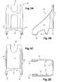
- the square piece 10 of the Figures 2A, 2B, 2C and 2D comprises an arm 11 with a notch or opening 16 in which elements of the counting assembly can be fixed.
- This arm is substantially perpendicular to the plate when the square part is put in place at the desired position along the plate and the assembly (platinum + square part) fixed on the support.
- the assembly platinum + square part fixed on the support.
- the arm 11 Along the two lateral edges of the arm 11 extend longitudinally two wings 12 which extend at a distance towards each of a support means (the second, here split by the fact of the presence of two wings, according to the terminology used) between the bracket and support face of the plate, having the second portion 13 of the indexing means to type of notches intended to come into contact with the complementary 5 of the plate 1.
- the lower portion 17 of the arm 11 also forms a support means (the first according to the terminology used) between the arm and counting face of the plate.
- Feet 14 are made on the support side of the end of the wings forming the second support so that the rail in place rests by said feet on the support and thus blocks completely in translation the parts at right angles to the plate 1.
- L-shaped legs 15 (optional) extending downwards the wings 12 ensure a better hold of the piece square on the plate before final fixing by avoiding that these elements can be detached too easily.
- the Figure 4B gives a perspective view of the square piece.
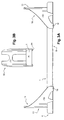
- FIGS. 3A and 3B show relationships between the two square pieces 10 and the plate 1 when they are positioned at their desired locations and the rail fixed on a support. It is understood that the spacing adjustment of the two arms 1 1, therefore of the two pieces at right angle 10, must be done before the plate 1 is mounted on the support or if it is mounted, before it is tightened so leave a free space between the feet 14 and the support and allow tilting inwardly of the piece square and unlocking the notching. Once the platen tight on the support, the feet 14 are applied to the support and the notches 5 and 13 engaged with each other thus preventing any displacement in translation of the part at right angles.
- first (face counting side) and second (side support side) supports, legs 14 and optional legs 15 are adapted to allow this translation when the plate is not in position. placed or clamped on the support, and the locking in translation, arms substantially perpendicular to the plate and parallel to each other, when the plate (the rail) is clamped on the support.
- the plate and the parts at right angle are made by molding plastic material.
- the rail can be delivered pre-assembled, that is to say pieces brackets inserted at the ends of the plate or not.
Landscapes
- Health & Medical Sciences (AREA)
- Life Sciences & Earth Sciences (AREA)
- Engineering & Computer Science (AREA)
- Hydrology & Water Resources (AREA)
- Public Health (AREA)
- Water Supply & Treatment (AREA)
- Physics & Mathematics (AREA)
- Fluid Mechanics (AREA)
- General Physics & Mathematics (AREA)
- Supports For Pipes And Cables (AREA)
- Connection Of Plates (AREA)
- Dental Tools And Instruments Or Auxiliary Dental Instruments (AREA)
- Measuring Volume Flow (AREA)
Abstract
L'invention concerne un rail de fixation d'un ensemble de comptage d'eau, le rail comportant, d'une part, une partie étendue en longueur dite platine (1) pouvant être fixé sur un support par une face support (3) de ladite platine et, d'autre part, deux bras latéraux (11) pour fixation amont et aval respectivement de l'ensemble de comptage, lesdits bras étant étendus sensiblement perpendiculairement par rapport à la platine coté face comptage (2) de ladite platine, la face support et la face comptage de la platine étant opposées. Selon l'invention, au moins un des bras latéraux est déplaçable en translation le long de la platine afin de pouvoir régler l'écartement entre les deux bras, le bras déplaçable faisant partie d'une pièce en équerre (10) qui lorsqu'elle est en place prend un premier appui (17) sur la face comptage (2) et un second appui (13) sur la face support (3) de la platine, le premier et le second appuis étant décalés longitudinalement le long de la platine. Des moyens d'indexation à crantages sont mis en oeuvre.The invention relates to a rail for fastening a water counting assembly, the rail comprising, on the one hand, a lengthwise extended part called platinum (1) which can be fixed on a support by a support face (3). said platen and, secondly, two lateral arms (11) for upstream and downstream attachment respectively of the counting assembly, said arms being extended substantially perpendicularly with respect to the platen side counting face (2) of said platen, the support face and the counting face of the plate being opposite. According to the invention, at least one of the lateral arms can be displaced in translation along the plate in order to be able to adjust the spacing between the two arms, the movable arm forming part of a square part (10) which when is in place takes a first support (17) on the counting face (2) and a second support (13) on the support face (3) of the plate, the first and the second supports being offset longitudinally along the plate. Indexing means with notches are implemented.
Description
L'invention concerne un rail de fixation d'un ensemble de comptage d'eau comportant des moyens de réglage permettant une adaptation à divers types d'ensemble de comptage. Elle a des applications dans le domaine du génie civil et plus particulièrement de l'adduction d'eau chez des utilisateurs.The invention relates to a rail for fixing a water counting assembly comprising adjustment means allowing adaptation to various types of counting assembly. It has applications in the field of civil engineering and more particularly water supply to users.
Les rails des fixations mis en oeuvre traditionnellement sont des structures rigides qui comportent une partie sensiblement horizontale qui se fixe sur un support de type mur nu ou fini et deux bras perpendiculaires à ses deux extrémités latérales et sur lesquels sont fixés les éléments d'extrémité de l'ensemble de comptage. Ce type de rail est généralement métallique, de préférence inox ou recouvert (peinture par exemple) pour éviter la détérioration par oxydation et/ou électrolyse dans un milieu généralement humide. On a également proposé de mettre en oeuvre des rails réalisés dans une matière plastique ce qui évite les inconvénients précédemment mentionnés.The rails of the fasteners used traditionally are rigid structures which comprise a substantially horizontal part which is fixed on a support of the bare or finished wall type and two arms perpendicular to its two lateral ends and on which are fixed the end elements of the counting set. This type of rail is generally metallic, preferably stainless or coated (eg paint) to prevent deterioration by oxidation and / or electrolysis in a generally humid environment. It has also been proposed to use rails made of a plastic material which avoids the disadvantages mentioned above.
Outre que les rails métalliques sont relativement coûteux en matière et en réalisation (découpe - emboutissage), qu'ils peuvent présenter des arêtes vives qui sont dangereuses, en général ces rails ne sont adaptés qu'à un ensemble de comptage spécifique, voire à une gamme très limitée d'éléments d'un ensemble de comptage particulier. Des stocks importants de modèles de rails sont donc nécessaires pour pouvoir s'adapter à des ensembles de comptages divers.In addition to the fact that the metal rails are relatively expensive in material and realization (cutting - stamping), that they can present sharp edges that are dangerous, in general these rails are only suitable for a specific counting set, or even a very limited range of elements of a particular counting set. Large stocks of rail models are therefore necessary to be able to adapt to various counting sets.
Il a été proposé des systèmes modulaires mais ils présentent eux-même des inconvénients propres comme par exemple une complexité de mise en oeuvre, des outils de réglage spécifiques, un encombrement important et des difficultés, voire impossibilité, pour changer les éléments, notamment robinetterie, de l'ensemble de comptage.Modular systems have been proposed, but they themselves have their own drawbacks, such as, for example, implementation complexity, specific adjustment tools, considerable bulk, and difficulties, if not impossibilities, for changing the elements, in particular taps, of the counting set.
Enfin, les rails connus présentent un inconvénient important lié à leur structure de fixation au support. En effet, la partie du rail destinée à venir contre le support est plane et le support ne l'est généralement pas. Il en résulte un positionnement hyperstatique qui génère des contraintes lors de la fixation et serrage du rail sur le support ce qui peut entraîner des déformations du rail et des désaxements des bras.Finally, the known rails have a significant disadvantage related to their support attachment structure. Indeed, the part of the rail intended to come against the support is flat and the support is generally not. This results in a hyperstatic positioning which generates constraints during the fixing and clamping of the rail on the support which can lead to deformation of the rail and misalignment of the arms.
La présente invention propose de remédier notamment aux inconvénients précédemment cités et d'apporter des avantages en termes notamment de simplification de mise en oeuvre, de stabilité, de coût et de réduction de stocks.The present invention proposes to remedy in particular the drawbacks mentioned above and to provide advantages in terms in particular of simplification of implementation, stability, cost and inventory reduction.
Ainsi, la présente invention concerne un rail de fixation d'un ensemble de comptage d'eau, le rail comportant, d'une part, une partie étendue en longueur dite platine pouvant être fixé sur un support par une face support de ladite platine et, d'autre part, deux bras latéraux pour fixation amont et aval respectivement de l'ensemble de comptage, lesdits bras étant étendus sensiblement perpendiculairement par rapport à la platine coté face comptage de ladite platine, la face support et la face comptage de la platine étant opposées.Thus, the present invention relates to a rail for fixing a water counting assembly, the rail comprising, on the one hand, a length-extending part called platinum which can be fixed on a support by a support face of said platen and on the other hand, two lateral arms for upstream and downstream fixing respectively of the counting assembly, said arms being extended substantially perpendicularly with respect to the plate side counting face of said platen, the support face and the counting face of the platen being opposed.
Selon l'invention, au moins un des bras latéraux est déplaçable en translation le long de la platine afin de pouvoir régler l'écartement entre les deux bras, le bras déplaçable faisant partie d'une pièce en équerre qui lorsqu'elle est en place prend un premier appui sur la face comptage et un second appui sur la face support de la platine, le premier et le second appuis étant décalés longitudinalement le long de la platine.According to the invention, at least one of the lateral arms can be displaced in translation along the plate so as to be able to adjust the spacing between the two arms, the movable arm forming part of a square part which when in place takes a first support on the counting face and a second support on the support face of the plate, the first and the second supports being offset longitudinally along the plate.
Dans divers modes de mise en oeuvre de l'invention, les moyens suivants pouvant être utilisés seuls ou selon toutes les combinaisons techniquement possibles, sont employés :
- sur la longueur de la platine, le premier appui est plus externe que le second appui, (c'est-à-dire que sur la longueur de la platine, le second appui est plus vers le milieu de la platine que le premier qui est plus vers une des extrémités de ladite platine)
- au moins un des appuis comporte des moyens complémentaires d'indexation permettant de bloquer la translation de la pièce en équerre une fois la position souhaitée atteinte,
- les moyens d'indexation sont à crantages,
- le premier appui comporte les moyens d'indexation qui sont à crantages,
- le second appui comporte les moyens d'indexation qui sont à crantages,
- les moyens d'indexation sont au niveau du premier appui entre une extrémité inférieure du bras et la face de comptage de la platine,
- la pièce en équerre comporte une aile centrale étendue longitudinalement entre le bras et le second appui par l'intérieur de la platine, ladite platine comportant une ouverture centrale longitudinale dans laquelle ladite aile peut circuler,
- les moyens d'indexation sont au niveau du second appui entre une extrémité d'indexation de l'aile et la face de comptage de la platine,
- le second appui est dédoublé respectivement le long de chacun des deux bords latéraux sur la face inférieure de la platine, la pièce en équerre comportant deux ailes latérales chacune étendue longitudinalement entre le bord correspondant du bras et le second appui dédoublé correspondant par l'extérieur de la platine,
- les moyens d'indexation sont au niveau d'un des seconds appuis dédoublés des deux ailes latérales,
- les moyens d'indexations à crantages sont au niveau de chacun des seconds appuis dédoublés des deux ailes latérales,
- les moyens d'indexations à crantages sont au niveau de chacun des seconds appuis dédoublés des deux ailes latérales,
- les deux bras latéraux sont déplaçables,
- la partie correspondant au second appui de la pièce en équerre comporte en outre coté support des moyens de type pied permettant à ladite partie de s'appuyer sur le support une fois le rail fixé sur ledit support,
- le rail (platine + bras) est dans une matière thermoplastique moulable,
- la matière thermoplastique est choisie pour sa résistance aux efforts mécaniques et est éventuellement combiné avec une ou des matières de renforcement, (par exemple des fibres),
- la matière thermoplastique est choisie parmi notamment le polypropylène, le polyoxyméthylène (POM) ou le polyamide,
- la platine est une pièce pleine,
- la platine est une pièce creuse comportant un nervurage interne de renforcement,
- le nervurage est coté face support de la platine,
- le rail est dans une matière thermoplastique moulable et la platine est une pièce creuse comportant un nervurage interne de renforcement coté face support,
- l'extrémité supérieure du bras comporte une ouverture en U ouvert vers le haut pour passage et fixation des éléments de l'ensemble de comptage,
- le bras vers son extrémité supérieure comporte un orifice circulaire pour passage et fixation des éléments de l'ensemble de comptage,
- une (deux dans le mode à deux bras latéraux réglables) pièce en équerre d'une hauteur déterminée est (sont) utilisée, choisie à partir d'un ensemble de pièces en équerres de hauteur de bras différentes,
- le rail ne comporte pas d'arête vive,
- la platine comporte face comptage des graduations sous forme de repères visibles permettant de déterminer l'écartement entre les deux bras en fonction de la position de chaque bras déplaçable par rapport à ses repères,
- la platine comporte au moins deux ouvertures pour passage de moyens de fixation (type vis, rivet ou autre équivalent) de la platine sur le support.
- along the length of the plate, the first support is more external than the second support, (that is to say that along the length of the plate, the second support is more toward the middle of the plate than the first one which is more towards one of the ends of said platen)
- at least one of the supports comprises complementary indexing means for blocking the translation of the piece at right angles once the desired position is reached,
- the indexing means are notched,
- the first support comprises the indexing means which are notched,
- the second support comprises the indexing means which are notched,
- the indexing means are at the level of the first support between a lower end of the arm and the counting face of the plate,
- the square part comprises a central wing extended longitudinally between the arm and the second support from the inside of the plate, said plate having a longitudinal central opening in which said wing can circulate,
- the indexing means are at the level of the second support between an indexing end of the wing and the counting face of the plate,
- the second support is split respectively along each of the two lateral edges on the lower face of the plate, the square part having two lateral wings each extended longitudinally between the corresponding edge of the arm and the second corresponding split support by the outside of platinum,
- the indexing means are at one of the second split supports of the two lateral wings,
- the indexing means with notches are at each second second support of the two lateral wings,
- the indexing means with notches are at each second second support of the two lateral wings,
- the two lateral arms are movable,
- the part corresponding to the second support of the square part further comprises support side foot-type means allowing said part to rest on the support once the rail fixed on said support,
- the rail (platinum + arm) is in a moldable thermoplastic material,
- the thermoplastic material is chosen for its resistance to mechanical forces and is optionally combined with one or more reinforcing materials, (for example fibers),
- the thermoplastic material is chosen from, in particular, polypropylene, polyoxymethylene (POM) or polyamide,
- platinum is a solid piece,
- the plate is a hollow part comprising an internal reinforcing rib,
- the rib is on the support side of the plate,
- the rail is made of a moldable thermoplastic material and the plate is a hollow part comprising an internal reinforcing rib on the support side,
- the upper end of the arm has an upwardly open U-shaped opening for passage and fixing of the elements of the counting assembly,
- the arm towards its upper end has a circular orifice for passage and fixing of the elements of the counting assembly,
- one (two in the mode with two adjustable side arms) square piece of a given height is (are) used, chosen from a set of pieces at right angles of different arm height,
- the rail does not have a sharp edge,
- the plate has face counting graduations in the form of visible marks to determine the spacing between the two arms depending on the position of each arm movable relative to its pins,
- the plate comprises at least two openings for passage of fastening means (screw, rivet or other equivalent type) of the plate on the support.
Le rail de l'invention est une structure modulable qui permet de nombreuses possibilités de montage. Par exemple des assemblages différents de robinetteries et compteur avec des longueurs différentes peuvent être montés grâce au réglage d'écartement et à la possibilité de mettre en oeuvre des bras de hauteurs différentes et des équerres avec des ouvertures différentes.The rail of the invention is a modular structure that allows many mounting possibilities. For example, different assemblies of valves and meters with different lengths can be fitted thanks to the gap adjustment and the possibility of using arms of different heights and brackets with different openings.
La présente invention, sans qu'elle en soit pour autant limitée, va maintenant être exemplifiée avec la description qui suit en relation avec les figures suivantes, d'un mode préféré de réalisation:
- les
Figures 1A, 1B et 1C qui sont des vues d'une platine respectivement latérale, de dessus (face comptage) et de dessous (face support), - les
Figures 2A, 2B, 2C et 2D qui sont des vues d'une pièce en équerre respectivement de dos ou externe, latérale, de face ou interne et de dessus, - les
Figures 3A et 3B qui sont des vues d'un rail respectivement latérale et de dos (ou externe), et - les
Figures 4A et 4B qui sont des vues perspectives respectivement d'un rail et d'une pièce en équerre.
- the
Figures 1A, 1B and 1C which are views of a plate respectively lateral, from above (face counting) and from below (face support), - the
Figures 2A, 2B, 2C and 2D which are views of an angled piece respectively from the back or outer, lateral, front or internal and from above, - the
Figures 3A and 3B which are views of a rail respectively lateral and back (or external), and - the
Figures 4A and 4B which are perspective views respectively of a rail and an angled piece.
L'exemple préféré présenté dans le détail est un rail qui met en oeuvre à chaque extrémité de la platine 1 une pièce en équerre 10 comportant deux ailes latérales 12 partant sur les bords latéraux du bras 11 de réception d'éléments de l'ensemble de comptage. On n'a pas détaillé ici le mode de réalisation à une seule aile partant longitudinalement de la partie médiane du bras et qui peut circuler dans une ouverture centrale de la platine.The preferred example presented in detail is a rail which implements at each end of the plate 1 a
Sur la
La pièce en équerre 10 des
Les
La platine et les pièces en équerre sont réalisées par moulage de matière plastique. On peut, pour une même platine, disposer de plusieurs gammes de pièces en équerre, notamment avec des ouvertures 16 de types différents (fermées - en O - ou ouvertes - en U - le long de leur pourtour), des hauteurs de bras différentes... Le rail peut être livré pré-monté, c'est-à-dire pièces en équerres insérées aux extrémités de la platine ou non.The plate and the parts at right angle are made by molding plastic material. We can, for the same platinum, have several ranges of pieces square, including
On comprend que l'invention peut être déclinée selon de nombreuses formes et modalités sans pour autant sortir du cadre défini par les revendications.It is understood that the invention can be declined in many forms and modalities without departing from the scope defined by the claims.
Claims (10)
caractérisé en ce qu'au moins un des bras latéraux est déplaçable en translation le long de la platine afin de pouvoir régler l'écartement entre les deux bras, le bras déplaçable faisant partie d'une pièce en équerre (10) qui lorsqu'elle est en place prend un premier appui (17) sur la face comptage (2) et un second appui (13) sur la face support (3) de la platine, le premier et le second appuis étant décalés longitudinalement le long de la platine.Rail for fixing a water counting assembly, the rail comprising, on the one hand, an extended portion in the so-called platinum length (1) that can be fixed on a support by a support face (3) of said platen and, on the other hand, two lateral arms (11) for upstream and downstream attachment respectively of the counting assembly, said arms being extended substantially perpendicularly with respect to the plate on the counter side (2) of said plate, the support face and the counting face of the platen being opposite,
characterized in that at least one of the lateral arms is displaceable in translation along the plate so as to be able to adjust the spacing between the two arms, the movable arm forming part of a square part (10) which when is in place takes a first support (17) on the counting face (2) and a second support (13) on the support face (3) of the plate, the first and the second supports being offset longitudinally along the plate.
Applications Claiming Priority (1)
| Application Number | Priority Date | Filing Date | Title |
|---|---|---|---|
| FR0755747A FR2917434B1 (en) | 2007-06-13 | 2007-06-13 | RAIL FOR FASTENING A WATER COUNTER ASSEMBLY |
Publications (2)
| Publication Number | Publication Date |
|---|---|
| EP2003255A1 true EP2003255A1 (en) | 2008-12-17 |
| EP2003255B1 EP2003255B1 (en) | 2009-07-15 |
Family
ID=39047502
Family Applications (1)
| Application Number | Title | Priority Date | Filing Date |
|---|---|---|---|
| EP20080305246 Active EP2003255B1 (en) | 2007-06-13 | 2008-06-11 | Attachment rail for a water metering assembly |
Country Status (4)
| Country | Link |
|---|---|
| EP (1) | EP2003255B1 (en) |
| DE (1) | DE602008000049D1 (en) |
| ES (1) | ES2330278T3 (en) |
| FR (1) | FR2917434B1 (en) |
Cited By (2)
| Publication number | Priority date | Publication date | Assignee | Title |
|---|---|---|---|---|
| WO2017129745A1 (en) * | 2016-01-29 | 2017-08-03 | Avl List Gmbh | Drive and control device for a throughflow measurement device |
| FR3160716A1 (en) | 2024-03-26 | 2025-10-03 | Sainte Lizaigne | Mounting kit for water distribution network user meter equipment, mounting rail |
Citations (2)
| Publication number | Priority date | Publication date | Assignee | Title |
|---|---|---|---|---|
| DE734050C (en) * | 1936-10-22 | 1943-04-07 | Otto Gatermann | Connection device for gas and water meter |
| DE19716165A1 (en) * | 1997-04-18 | 1998-10-22 | Ewe Wilhelm Gmbh & Co Kg | Mounting for water or gas meter |
-
2007
- 2007-06-13 FR FR0755747A patent/FR2917434B1/en not_active Expired - Fee Related
-
2008
- 2008-06-11 EP EP20080305246 patent/EP2003255B1/en active Active
- 2008-06-11 DE DE200860000049 patent/DE602008000049D1/en active Active
- 2008-06-11 ES ES08305246T patent/ES2330278T3/en active Active
Patent Citations (2)
| Publication number | Priority date | Publication date | Assignee | Title |
|---|---|---|---|---|
| DE734050C (en) * | 1936-10-22 | 1943-04-07 | Otto Gatermann | Connection device for gas and water meter |
| DE19716165A1 (en) * | 1997-04-18 | 1998-10-22 | Ewe Wilhelm Gmbh & Co Kg | Mounting for water or gas meter |
Cited By (4)
| Publication number | Priority date | Publication date | Assignee | Title |
|---|---|---|---|---|
| WO2017129745A1 (en) * | 2016-01-29 | 2017-08-03 | Avl List Gmbh | Drive and control device for a throughflow measurement device |
| CN108496063A (en) * | 2016-01-29 | 2018-09-04 | Avl列表有限责任公司 | Drive controls for flow measuring devices |
| JP2019503487A (en) * | 2016-01-29 | 2019-02-07 | アーファウエル リスト ゲゼルシャフト ミット ベシュレンクテル ハフツング | Drive and control device for flow meter |
| FR3160716A1 (en) | 2024-03-26 | 2025-10-03 | Sainte Lizaigne | Mounting kit for water distribution network user meter equipment, mounting rail |
Also Published As
| Publication number | Publication date |
|---|---|
| DE602008000049D1 (en) | 2009-08-27 |
| FR2917434B1 (en) | 2009-10-02 |
| FR2917434A1 (en) | 2008-12-19 |
| ES2330278T3 (en) | 2009-12-07 |
| EP2003255B1 (en) | 2009-07-15 |
Similar Documents
| Publication | Publication Date | Title |
|---|---|---|
| EP3090850B1 (en) | Means for attaching surface coating blades and use | |
| EP2003255B1 (en) | Attachment rail for a water metering assembly | |
| CA2973677A1 (en) | Device for attaching a solar panel | |
| BE1018205A5 (en) | FINISHING ASSEMBLY FOR FLOORING AT LEAST TWO FUNCTIONS. | |
| CA2194871A1 (en) | Adjustable staircase | |
| FR2786857A1 (en) | REFRIGERATING APPLIANCE DOOR WITH MULTI-PIECE COATING OR EXTERIOR SIDING | |
| FR2989396A1 (en) | EXTENSIBLE SUSPENSION | |
| FR2717753A1 (en) | Device for mounting a bumper on the bodywork of a motor vehicle. | |
| EP2955302B1 (en) | Opening section or frame profile for window | |
| FR3082467A1 (en) | DEVICE FOR MOVING A COMPONENT OF A SEAT | |
| FR2711699A1 (en) | Device for immobilizing a vertical stiffener for a railing with respect to a support for supporting the ground. | |
| EP1722111B1 (en) | Fastening device for fastening a metal profile on a support | |
| FR2828903A1 (en) | WIDE FLEXIBLE BLADE FIXING BRACKET | |
| EP1972750A1 (en) | Roller blind guiderail | |
| EP2501876B1 (en) | Railing formed of a set of ready-to-assemble detached parts | |
| FR3011571A1 (en) | BAY OF BUILDING COMPRISING AN OPENING EQUIPPED WITH A JOINERY | |
| FR3026120B1 (en) | BUTTERFLY TYPE INSTALLATION DEVICE | |
| EP1150409A1 (en) | Cable duct sections, cable duct obtained by asembling at least 2 two sections and mounting process | |
| EP0534880B1 (en) | Connecting device for hollow girders or similar hollow elements for decorative use | |
| FR3026771A1 (en) | METHOD OF INSTALLING A DORMANT SUITABLE FOR SLIDING ORCHOOLS AND INTEGRATED DORMANT SUITABLE FOR SAID METHOD OF INSTALLATION | |
| FR2966861B1 (en) | DRIVE ELEMENT FOR WINDOW LIFTING DEVICE | |
| FR3022275A1 (en) | RAIL FOR THE INSTALLATION OF INSULATION ON AN EXTERIOR FACADE OF BUILDING | |
| FR3164238A1 (en) | Roller shutter tube support, sub-assembly and associated protective installation | |
| FR2913704A1 (en) | Office's walls connecting method, involves realizing connection between walls by bringing one profile in contact with another profile, where end of sides of latter profile and base of latter profile are engaged with part of former profile | |
| FR2825410A1 (en) | ROLLER SHUTTER SUPPORT |
Legal Events
| Date | Code | Title | Description |
|---|---|---|---|
| PUAI | Public reference made under article 153(3) epc to a published international application that has entered the european phase |
Free format text: ORIGINAL CODE: 0009012 |
|
| AK | Designated contracting states |
Kind code of ref document: A1 Designated state(s): AT BE BG CH CY CZ DE DK EE ES FI FR GB GR HR HU IE IS IT LI LT LU LV MC MT NL NO PL PT RO SE SI SK TR |
|
| AX | Request for extension of the european patent |
Extension state: AL BA MK RS |
|
| 17P | Request for examination filed |
Effective date: 20081203 |
|
| GRAP | Despatch of communication of intention to grant a patent |
Free format text: ORIGINAL CODE: EPIDOSNIGR1 |
|
| GRAS | Grant fee paid |
Free format text: ORIGINAL CODE: EPIDOSNIGR3 |
|
| GRAA | (expected) grant |
Free format text: ORIGINAL CODE: 0009210 |
|
| AK | Designated contracting states |
Kind code of ref document: B1 Designated state(s): AT BE BG CH CY CZ DE DK EE ES FI FR GB GR HR HU IE IS IT LI LT LU LV MC MT NL NO PL PT RO SE SI SK TR |
|
| REG | Reference to a national code |
Ref country code: GB Ref legal event code: FG4D Free format text: NOT ENGLISH Ref country code: CH Ref legal event code: EP |
|
| REG | Reference to a national code |
Ref country code: IE Ref legal event code: FG4D |
|
| AKX | Designation fees paid |
Designated state(s): AT BE BG CH CY CZ DE DK EE ES FI FR GB GR HR HU IE IS IT LI LT LU LV MC MT NL NO PL PT RO SE SI SK TR |
|
| REF | Corresponds to: |
Ref document number: 602008000049 Country of ref document: DE Date of ref document: 20090827 Kind code of ref document: P |
|
| REG | Reference to a national code |
Ref country code: DE Ref legal event code: R096 Ref document number: 602008000049 Country of ref document: DE Effective date: 20090827 |
|
| REG | Reference to a national code |
Ref country code: RO Ref legal event code: EPE |
|
| RAP2 | Party data changed (patent owner data changed or rights of a patent transferred) |
Owner name: SAINTE LIZAIGNE SA |
|
| REG | Reference to a national code |
Ref country code: CH Ref legal event code: NV Representative=s name: KIRKER & CIE S.A. |
|
| NLT2 | Nl: modifications (of names), taken from the european patent patent bulletin |
Owner name: SAINTE LIZAIGNE SA Effective date: 20091014 |
|
| REG | Reference to a national code |
Ref country code: ES Ref legal event code: FG2A Ref document number: 2330278 Country of ref document: ES Kind code of ref document: T3 |
|
| PG25 | Lapsed in a contracting state [announced via postgrant information from national office to epo] |
Ref country code: LT Free format text: LAPSE BECAUSE OF FAILURE TO SUBMIT A TRANSLATION OF THE DESCRIPTION OR TO PAY THE FEE WITHIN THE PRESCRIBED TIME-LIMIT Effective date: 20090715 Ref country code: SE Free format text: LAPSE BECAUSE OF FAILURE TO SUBMIT A TRANSLATION OF THE DESCRIPTION OR TO PAY THE FEE WITHIN THE PRESCRIBED TIME-LIMIT Effective date: 20090715 Ref country code: FI Free format text: LAPSE BECAUSE OF FAILURE TO SUBMIT A TRANSLATION OF THE DESCRIPTION OR TO PAY THE FEE WITHIN THE PRESCRIBED TIME-LIMIT Effective date: 20090715 Ref country code: IS Free format text: LAPSE BECAUSE OF FAILURE TO SUBMIT A TRANSLATION OF THE DESCRIPTION OR TO PAY THE FEE WITHIN THE PRESCRIBED TIME-LIMIT Effective date: 20091115 Ref country code: NO Free format text: LAPSE BECAUSE OF FAILURE TO SUBMIT A TRANSLATION OF THE DESCRIPTION OR TO PAY THE FEE WITHIN THE PRESCRIBED TIME-LIMIT Effective date: 20091015 Ref country code: AT Free format text: LAPSE BECAUSE OF FAILURE TO SUBMIT A TRANSLATION OF THE DESCRIPTION OR TO PAY THE FEE WITHIN THE PRESCRIBED TIME-LIMIT Effective date: 20090715 |
|
| REG | Reference to a national code |
Ref country code: IE Ref legal event code: FD4D |
|
| PG25 | Lapsed in a contracting state [announced via postgrant information from national office to epo] |
Ref country code: SI Free format text: LAPSE BECAUSE OF FAILURE TO SUBMIT A TRANSLATION OF THE DESCRIPTION OR TO PAY THE FEE WITHIN THE PRESCRIBED TIME-LIMIT Effective date: 20090715 Ref country code: HR Free format text: LAPSE BECAUSE OF FAILURE TO SUBMIT A TRANSLATION OF THE DESCRIPTION OR TO PAY THE FEE WITHIN THE PRESCRIBED TIME-LIMIT Effective date: 20090715 Ref country code: LV Free format text: LAPSE BECAUSE OF FAILURE TO SUBMIT A TRANSLATION OF THE DESCRIPTION OR TO PAY THE FEE WITHIN THE PRESCRIBED TIME-LIMIT Effective date: 20090715 Ref country code: PL Free format text: LAPSE BECAUSE OF FAILURE TO SUBMIT A TRANSLATION OF THE DESCRIPTION OR TO PAY THE FEE WITHIN THE PRESCRIBED TIME-LIMIT Effective date: 20090715 |
|
| PG25 | Lapsed in a contracting state [announced via postgrant information from national office to epo] |
Ref country code: BG Free format text: LAPSE BECAUSE OF FAILURE TO SUBMIT A TRANSLATION OF THE DESCRIPTION OR TO PAY THE FEE WITHIN THE PRESCRIBED TIME-LIMIT Effective date: 20091015 |
|
| PG25 | Lapsed in a contracting state [announced via postgrant information from national office to epo] |
Ref country code: IE Free format text: LAPSE BECAUSE OF FAILURE TO SUBMIT A TRANSLATION OF THE DESCRIPTION OR TO PAY THE FEE WITHIN THE PRESCRIBED TIME-LIMIT Effective date: 20090715 Ref country code: EE Free format text: LAPSE BECAUSE OF FAILURE TO SUBMIT A TRANSLATION OF THE DESCRIPTION OR TO PAY THE FEE WITHIN THE PRESCRIBED TIME-LIMIT Effective date: 20090715 Ref country code: DK Free format text: LAPSE BECAUSE OF FAILURE TO SUBMIT A TRANSLATION OF THE DESCRIPTION OR TO PAY THE FEE WITHIN THE PRESCRIBED TIME-LIMIT Effective date: 20090715 |
|
| PLBE | No opposition filed within time limit |
Free format text: ORIGINAL CODE: 0009261 |
|
| STAA | Information on the status of an ep patent application or granted ep patent |
Free format text: STATUS: NO OPPOSITION FILED WITHIN TIME LIMIT |
|
| PG25 | Lapsed in a contracting state [announced via postgrant information from national office to epo] |
Ref country code: SK Free format text: LAPSE BECAUSE OF FAILURE TO SUBMIT A TRANSLATION OF THE DESCRIPTION OR TO PAY THE FEE WITHIN THE PRESCRIBED TIME-LIMIT Effective date: 20090715 |
|
| 26N | No opposition filed |
Effective date: 20100416 |
|
| REG | Reference to a national code |
Ref country code: DE Ref legal event code: R097 Ref document number: 602008000049 Country of ref document: DE Effective date: 20100416 |
|
| PG25 | Lapsed in a contracting state [announced via postgrant information from national office to epo] |
Ref country code: GR Free format text: LAPSE BECAUSE OF FAILURE TO SUBMIT A TRANSLATION OF THE DESCRIPTION OR TO PAY THE FEE WITHIN THE PRESCRIBED TIME-LIMIT Effective date: 20091016 |
|
| PG25 | Lapsed in a contracting state [announced via postgrant information from national office to epo] |
Ref country code: MT Free format text: LAPSE BECAUSE OF FAILURE TO SUBMIT A TRANSLATION OF THE DESCRIPTION OR TO PAY THE FEE WITHIN THE PRESCRIBED TIME-LIMIT Effective date: 20090715 |
|
| PG25 | Lapsed in a contracting state [announced via postgrant information from national office to epo] |
Ref country code: CY Free format text: LAPSE BECAUSE OF FAILURE TO SUBMIT A TRANSLATION OF THE DESCRIPTION OR TO PAY THE FEE WITHIN THE PRESCRIBED TIME-LIMIT Effective date: 20090715 |
|
| PG25 | Lapsed in a contracting state [announced via postgrant information from national office to epo] |
Ref country code: HU Free format text: LAPSE BECAUSE OF FAILURE TO SUBMIT A TRANSLATION OF THE DESCRIPTION OR TO PAY THE FEE WITHIN THE PRESCRIBED TIME-LIMIT Effective date: 20100116 Ref country code: PT Free format text: LAPSE BECAUSE OF FAILURE TO SUBMIT A TRANSLATION OF THE DESCRIPTION OR TO PAY THE FEE WITHIN THE PRESCRIBED TIME-LIMIT Effective date: 20091215 |
|
| PG25 | Lapsed in a contracting state [announced via postgrant information from national office to epo] |
Ref country code: TR Free format text: LAPSE BECAUSE OF FAILURE TO SUBMIT A TRANSLATION OF THE DESCRIPTION OR TO PAY THE FEE WITHIN THE PRESCRIBED TIME-LIMIT Effective date: 20090715 |
|
| REG | Reference to a national code |
Ref country code: FR Ref legal event code: PLFP Year of fee payment: 9 |
|
| REG | Reference to a national code |
Ref country code: FR Ref legal event code: PLFP Year of fee payment: 10 |
|
| REG | Reference to a national code |
Ref country code: FR Ref legal event code: PLFP Year of fee payment: 11 |
|
| P01 | Opt-out of the competence of the unified patent court (upc) registered |
Effective date: 20230526 |
|
| PGFP | Annual fee paid to national office [announced via postgrant information from national office to epo] |
Ref country code: DE Payment date: 20250416 Year of fee payment: 18 |
|
| PGFP | Annual fee paid to national office [announced via postgrant information from national office to epo] |
Ref country code: GB Payment date: 20250415 Year of fee payment: 18 |
|
| PGFP | Annual fee paid to national office [announced via postgrant information from national office to epo] |
Ref country code: IT Payment date: 20250424 Year of fee payment: 18 Ref country code: NL Payment date: 20250618 Year of fee payment: 18 |
|
| PGFP | Annual fee paid to national office [announced via postgrant information from national office to epo] |
Ref country code: RO Payment date: 20250611 Year of fee payment: 18 |
|
| PGFP | Annual fee paid to national office [announced via postgrant information from national office to epo] |
Ref country code: CZ Payment date: 20250603 Year of fee payment: 18 |
|
| PGFP | Annual fee paid to national office [announced via postgrant information from national office to epo] |
Ref country code: ES Payment date: 20250708 Year of fee payment: 18 |
|
| PGFP | Annual fee paid to national office [announced via postgrant information from national office to epo] |
Ref country code: CH Payment date: 20250701 Year of fee payment: 18 |
|
| PGFP | Annual fee paid to national office [announced via postgrant information from national office to epo] |
Ref country code: MC Payment date: 20260313 Year of fee payment: 19 |
|
| PGFP | Annual fee paid to national office [announced via postgrant information from national office to epo] |
Ref country code: LU Payment date: 20260309 Year of fee payment: 19 Ref country code: BE Payment date: 20260309 Year of fee payment: 19 |
|
| PGFP | Annual fee paid to national office [announced via postgrant information from national office to epo] |
Ref country code: FR Payment date: 20260309 Year of fee payment: 19 |