EP2003342A2 - Procédé de fonctionnement d'un agencement doté d'une pompe à vide et agencement doté d'une pompe à vide - Google Patents
Procédé de fonctionnement d'un agencement doté d'une pompe à vide et agencement doté d'une pompe à vide Download PDFInfo
- Publication number
- EP2003342A2 EP2003342A2 EP08009333A EP08009333A EP2003342A2 EP 2003342 A2 EP2003342 A2 EP 2003342A2 EP 08009333 A EP08009333 A EP 08009333A EP 08009333 A EP08009333 A EP 08009333A EP 2003342 A2 EP2003342 A2 EP 2003342A2
- Authority
- EP
- European Patent Office
- Prior art keywords
- vacuum pump
- bias
- magnetic bearing
- bias current
- arrangement
- Prior art date
- Legal status (The legal status is an assumption and is not a legal conclusion. Google has not performed a legal analysis and makes no representation as to the accuracy of the status listed.)
- Granted
Links
Images


Classifications
-
- F—MECHANICAL ENGINEERING; LIGHTING; HEATING; WEAPONS; BLASTING
- F04—POSITIVE - DISPLACEMENT MACHINES FOR LIQUIDS; PUMPS FOR LIQUIDS OR ELASTIC FLUIDS
- F04D—NON-POSITIVE-DISPLACEMENT PUMPS
- F04D19/00—Axial-flow pumps
- F04D19/02—Multi-stage pumps
- F04D19/04—Multi-stage pumps specially adapted to the production of a high vacuum, e.g. molecular pumps
- F04D19/048—Multi-stage pumps specially adapted to the production of a high vacuum, e.g. molecular pumps comprising magnetic bearings
-
- F—MECHANICAL ENGINEERING; LIGHTING; HEATING; WEAPONS; BLASTING
- F04—POSITIVE - DISPLACEMENT MACHINES FOR LIQUIDS; PUMPS FOR LIQUIDS OR ELASTIC FLUIDS
- F04D—NON-POSITIVE-DISPLACEMENT PUMPS
- F04D27/00—Control, e.g. regulation, of pumps, pumping installations or pumping systems specially adapted for elastic fluids
- F04D27/02—Surge control
- F04D27/0292—Stop safety or alarm devices, e.g. stop-and-go control; Disposition of check-valves
-
- F—MECHANICAL ENGINEERING; LIGHTING; HEATING; WEAPONS; BLASTING
- F04—POSITIVE - DISPLACEMENT MACHINES FOR LIQUIDS; PUMPS FOR LIQUIDS OR ELASTIC FLUIDS
- F04D—NON-POSITIVE-DISPLACEMENT PUMPS
- F04D29/00—Details, component parts, or accessories
- F04D29/05—Shafts or bearings, or assemblies thereof, specially adapted for elastic fluid pumps
- F04D29/056—Bearings
- F04D29/058—Bearings magnetic; electromagnetic
-
- F—MECHANICAL ENGINEERING; LIGHTING; HEATING; WEAPONS; BLASTING
- F16—ENGINEERING ELEMENTS AND UNITS; GENERAL MEASURES FOR PRODUCING AND MAINTAINING EFFECTIVE FUNCTIONING OF MACHINES OR INSTALLATIONS; THERMAL INSULATION IN GENERAL
- F16C—SHAFTS; FLEXIBLE SHAFTS; ELEMENTS OR CRANKSHAFT MECHANISMS; ROTARY BODIES OTHER THAN GEARING ELEMENTS; BEARINGS
- F16C32/00—Bearings not otherwise provided for
- F16C32/04—Bearings not otherwise provided for using magnetic or electric supporting means
- F16C32/0406—Magnetic bearings
- F16C32/044—Active magnetic bearings
- F16C32/0444—Details of devices to control the actuation of the electromagnets
-
- F—MECHANICAL ENGINEERING; LIGHTING; HEATING; WEAPONS; BLASTING
- F16—ENGINEERING ELEMENTS AND UNITS; GENERAL MEASURES FOR PRODUCING AND MAINTAINING EFFECTIVE FUNCTIONING OF MACHINES OR INSTALLATIONS; THERMAL INSULATION IN GENERAL
- F16C—SHAFTS; FLEXIBLE SHAFTS; ELEMENTS OR CRANKSHAFT MECHANISMS; ROTARY BODIES OTHER THAN GEARING ELEMENTS; BEARINGS
- F16C32/00—Bearings not otherwise provided for
- F16C32/04—Bearings not otherwise provided for using magnetic or electric supporting means
- F16C32/0406—Magnetic bearings
- F16C32/044—Active magnetic bearings
- F16C32/0474—Active magnetic bearings for rotary movement
- F16C32/0489—Active magnetic bearings for rotary movement with active support of five degrees of freedom, e.g. two radial magnetic bearings combined with an axial bearing
-
- F—MECHANICAL ENGINEERING; LIGHTING; HEATING; WEAPONS; BLASTING
- F16—ENGINEERING ELEMENTS AND UNITS; GENERAL MEASURES FOR PRODUCING AND MAINTAINING EFFECTIVE FUNCTIONING OF MACHINES OR INSTALLATIONS; THERMAL INSULATION IN GENERAL
- F16C—SHAFTS; FLEXIBLE SHAFTS; ELEMENTS OR CRANKSHAFT MECHANISMS; ROTARY BODIES OTHER THAN GEARING ELEMENTS; BEARINGS
- F16C2360/00—Engines or pumps
- F16C2360/44—Centrifugal pumps
- F16C2360/45—Turbo-molecular pumps
Definitions
- the invention relates to a method for operating an arrangement with a vacuum pump according to the preamble of the first claim. It also relates to an arrangement with a vacuum pump according to the preamble of the seventh claim.
- Vacuum pumps with high-speed rotors have helped to open up new fields of technology, for example in semiconductor physics, due to the purity of the high vacuum produced.
- the development leads to ever smaller component structures that have to be generated or investigated. This means that the recipients, in which these tasks are solved, may be exposed to ever lower mechanical impairments.
- Such impairments are, for example, the vibrations that generate the vacuum pump due to the rapid rotation of the rotor.
- vacuum pumps in which the rotor is mounted on magnetic principles produce less vibration, it can be seen that the vibrations are often too strong for today's requirements.
- damping body This is a component arranged between the vacuum pump and the recipient, for example after EP 1711 711 A1 .
- damping body acts only at high frequencies. At low frequencies in particular, damping is particularly important since mechanical resonances (in the recipient, eg sample holders) are generally low.
- the effect on the frequency is limited downwards, as the Vibration transfer function would be perfect if the stiffness of the damping body would go to zero.
- This is not possible because the force generated by the atmospheric pressure must be absorbed.
- An arranged between the recipient and vacuum pump component generates a reluctant to accept loss of conductance.
- an additional backup of the pump is required, since in the case of contact of rotor and stator forces can not be held by the damping body.
- the DE 32 39 328 A1 suggests a weakening within the pump by soft suspension of the bearing stator of permanent magnet bearings.
- This principle is used in the EP 1 118 774 A1 also used for suspension of a housing part in which an active magnetic bearing is arranged.
- This structure has a similar frequency dependence as an external damping body, so that the disadvantages mentioned above in this context also apply to this solution.
- Another disadvantage is that the soft suspension creates additional radial play. This means either an increase in the effective backup game play, which is disadvantageous in resulting during the retractable bearing forces, or the need to reduce the game to the first fishing camp contact. This results in a lower robustness, since an event for bringing a Fanglager Scotlandes in this structure is weaker.
- this solution is usually accompanied by a high mechanical complexity, since usually mobility in the radial direction must be realized with infinite stiffness in the axial direction.
- the object of the invention is to provide a vacuum pump with magnetic bearing that transmits less vibration to the recipient, it is simple and inexpensive to manufacture and avoids the aforementioned disadvantages.
- a reduction of the bias causes a reduction in the forces acting in the camp.
- Mechanical vibrations are caused, for example, by electronic noise, which is converted by the electromagnet of the bearing into unwanted force changes.
- Electronics noise is caused, among other things, by electromagnetic interference in lines or by quantization noise from digital-analog and analog-to-digital converters.
- the lowering takes place depending on the switching state of a switching means. As a result, the lowering takes place only when the smooth running of the vacuum pump is needed. In such a phase is not expected to great shocks that must be compensated by the magnetic bearing.
- the normal value is determined by what the magnetic bearing needs to provide in terms of forces to compensate for rotor motion.
- the switching means thus allows the lowest possible lowering of the bias and allows the user of the vacuum pump to selectively switch to an operating mode in which as few vibrations as possible are generated by the vacuum pump.
- the vacuum pump becomes aware of a value operated for the bias, which is considered inadmissible in the prior art.
- the problems, especially the small possible force changes are circumvented by providing a switching means. This switching means allows to limit the low bias operation to a temporal range.
- the previously reduced bias is increased by changing the bias current after a preselected period of time.
- the reduction of the bias is thus performed only for the length of a process, such as a measurement or exposure.
- the duration can be freely selectable. It eliminates a manual switching operation.
- the deflection of the rotor is monitored by a position sensor and, when a limit value of the deflection is exceeded, the bias current is changed such that the bias is increased. This measure increases the reliability of the arrangement. If an increase in the deflections is measured by the position sensor, this indicates a state of the arrangement in which even greater deflections can be expected.
- the bias generated by the control electronics in the electromagnet is then increased, so that the achievable by a current change force changes are again large enough to be able to dominate even larger deflections of the rotor.
- bias current In a development of the bias current is changed in the form of a continuous function. This avoids sudden changes, which can trigger vibration processes in various ways.
- Another development provides to make the change of the bias current by an amount that depends on the installation position of the vacuum pump.
- the magnetic bearing must be able to support the rotor at least against gravity. It has to apply at least the force corresponding to the component of the weight of the rotor in bearing force acting direction.
- the preceding development can be further developed such that the amount of change in the bias current during storage of the rotor is greater parallel to the direction of gravity than in an arrangement perpendicular to it. This ensures that the vacuum pump can be installed in any position, the force on the one hand always sufficient to support against the weight, on the other hand, is as small as possible.
- the arrangement according to claim 7 can be further developed, in which the switching means comprises a housing accessible to the control electronics switching element. As a result, a simple operation is created.
- the switching means comprises an electronic unit which can be connected to a vacuum pump or control electronics.
- a vacuum pump or control electronics This can be, for example, a manual control unit. It can also be a computer or similar device.
- the magnetic bearing has a permanent magnet. It generates a constant magnetic field to support the rotor. Since this magnetic field is a material property and constant, there are no sources in the generation, which can lead to vibrations of the rotor and the vacuum pump.
- the arrangement has status indicating means which indicate when the arrangement is in the state with a changed bias current. This indicates that the device must not be subjected to strong vibrations or other mechanical disturbances.
- FIG. 1 an arrangement with a vacuum pump 1 is shown.
- This vacuum pump is fastened with fastening means 3 releasably attached to the flange of a recipient 2.
- the fasteners shown are screws, but brackets and other known means may be used.
- a rotor shaft 6 which carries a bell-shaped rotor 7.
- rotor blades 8 are arranged. These are arranged in several axially spaced planes.
- stator blades 9 are also arranged in axially spaced planes.
- the rotor shaft is supported rotatably by active magnetic bearings.
- active magnetic bearings In the example shown, these are two active radial magnetic bearings and one active axial magnetic bearing.
- first electromagnet 10 of the first radial bearing In the direction of that shaft end, to which the rotor shaft is connected to the rotor, there is a first electromagnet 10 of the first radial bearing.
- Such a radial bearing has two pairs of electromagnets in a conventional design. The effective directions of the pairs are perpendicular to each other and to the rotor shaft. It is followed in the direction of the opposite end of the shaft, a first radial sensor 11. It follows in the order mentioned the engine, a second solenoid 12 of the second radial bearing and a second radial sensor 13.
- the second radial bearing also has a permanent magnet 14, which is arranged in the magnetic circuit of the second electromagnet. It causes a permanent magnetic bias of this magnetic circuit.
- the axial degree of freedom of the rotor shaft is supported by a thrust bearing. This is arranged at that shaft end, which is opposite to the transition to the bell-shaped rotor.
- the thrust bearing has axial electromagnets 15 and an axial sensor 16. Motor and electromagnets of the radial and axial magnetic bearings are supplied by supply lines 17 with the necessary electrical voltages and currents.
- a part of the magnetic bearings can be made fully permanent magnetic.
- a design with rotor disks mounted on the shaft can be selected.
- the rotor may also have pump sections with different principles of operation, for example Holweckmatn.
- a multi-core supply cable 18 connects control electronics 20 to the supply lines 17 of the vacuum pump.
- the control electronics generates the necessary currents and voltages to the rotor against the weight in Hold the levitation and turn over the engine in rapid rotation. It is arranged in a housing 21. On its surface, a switching means 22 and a status indicating means 23 are provided.
- the switching means is connected to the control electronics 20, so that it provides the bias current of at least one of the bearings as a function of the switching state.
- the switching means is designed as a switch in the example shown.
- the status indicating means indicates that the vacuum pump is in a reduced bias operating condition.
- the status display means is designed as a light-emitting diode in the present example.
- an electronic unit 31 may be connected via a connecting cable 30 to the control electronics.
- This unit may be a hand-held device, a portable computer or a control unit connected via a common bus system.
- the connection can be made via the connection cable, via radio or via optical data transmission.
- the connection can be permanent or detachable.
- the electronic unit may have other functions, such as changing operating parameters and the like.
- the amount for changing the bias current may be one of the operating parameters. Another operating parameter is, for example, the speed.
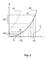
- the characteristic curve 40 is that of a purely electromagnetic magnetic bearing, the characteristic 41 corresponds to that of a magnetically biased with permanent magnet magnetic bearing. This characteristic is parabolic in a good approximation. This course is for the Force generation through a magnetic bearing important. In the following, two different operating points lying on the characteristic curve 40 are compared.
- a first operating point is defined by a bias current I 1 .
- This bias current current changes in a current range .DELTA.I 1 are performed. These current changes cause force changes in the range ⁇ F 1 . With these force changes, the rotor position can be influenced and, for example, be reacted to disturbances.
- a second operating point is defined by a bias current I 2 .
- current changes lead to force changes.
- a dashed line separates two areas.
- the area A indicates the part of the characteristic curve 40 in which magnetic bearings of vacuum pumps are operated in the prior art.
- the operating point is chosen so that with a current change at any time sufficient force change can be generated to counteract deflections of the rotor.
- the maximum deflections are empirical values of the manufacturer of the vacuum pump. Such deflections are usually due to mechanical effects, such as the closing of slide valves connected to the recipient, and the like.
- the maximum possible current changes that can be generated by the control electronics are constructional limits.
- the area B is located in the lower part of the characteristic 40.
- the force changes that can be achieved through maximum current change are only sufficient to compensate for the smallest disturbances.
- Large vibrations of the pump can no longer or only be intercepted by using emergency camps.
- the control electronics are caused to move the operating point from the area A to the area B.
- the lower forces and force changes in the area of disadvantage Therefore, the prior art refrains from operating in this area.
- the advantage of operating in this area is that the lower base forces in the magnetic bearing cause a low vibration transmission.
- unavoidable electronic noise which causes unwanted changes in current, causes only minor unwanted force changes. This contributes to lowering the vibrations generated by the vacuum pump and transmitted to the recipient.
- Magnetic bearings with permanent magnets which are arranged within the magnetic circuit, have a force-current characteristic which, like characteristic 41 in FIG Fig. 2 runs.
- the bias is composed in such a camp of two shares, one of which is permanently magnetic, the other is generated electromagnetically. Often such bearings are referred to as permanently biased magnetic.
- the electromagnetic component is determined by the size of the bias current.
- the permanent magnets are designed such that the bias current is zero.
- the bias is generated partly by means of a non-zero bias current and partly by means of permanent magnets.
- the force-current characteristic of the permanent magnetically biased magnetic bearing is shifted to the left compared to the one shown in the diagram.
- the choice of Operating point takes place according to the same criteria as in the case of purely electromagnetic bearing.
- the operating point in the normal region A can be chosen so that the bias current assumes the value zero.
- the area B is then located so that a bias current is used to compensate for the permanent magnetic bias.
- Fig. 3 The time course of some sizes of the arrangement with a vacuum pump is in Fig. 3 shown.
- the uppermost diagram shows the switching state S of the switching means. Below this follows in this order: amount of bias V, bias current in case of a permanent magnetic assisted bearing I PM , bias current in a purely electromagnetic bearing I before and the speed of the rotor f.
- the switching state of the switching means changes. This can be done, for example, by flipping a switch or sending a control command via an interface to the control electronics.
- a steady change in the bias is performed. It drops from a first, higher value to a second, lower value. This is caused by a change in the bias currents.
- the change in the bias current I PM is dependent on the ratio of the components of permanent magnetization and biasing caused by a bias current. Generally, a reduction of the bias current is made. The permanent magnetic components must be compensated to lower the bias by the bias current. This may result in a sign change of the bias current, as shown in the figure.
- I PM before time t 0 and after time t 3 equal to zero.
- the course shown corresponds to a magnetic bearing, which is biased only partially permanent magnetically, so that the bias current I PM is different from zero even before the time t 0 and after the time t 3 and between t 1 and t 2 has a different sign.
- the bias current I Vor decreases from a high value to a lower value.
- An advantageous time period between the times t 0 and t 1 is a few tenths of a second to a few seconds.
- V, I PM, and I maintain their values before .
- V, I PM, and I maintain their values before .
- This length of time may be of selected length.
- One way of implementation is to set the duration of an example stored in the control electronics operating parameters.
- the switching state is changed again, it assumes the original state again.
- the bias then rises again to the original value. This is effected by the change of the bias current in the form of a decrease of I PM and increase of I Before to the respective output value.
Landscapes
- Engineering & Computer Science (AREA)
- General Engineering & Computer Science (AREA)
- Mechanical Engineering (AREA)
- Physics & Mathematics (AREA)
- Electromagnetism (AREA)
- Magnetic Bearings And Hydrostatic Bearings (AREA)
- Non-Positive Displacement Air Blowers (AREA)
Applications Claiming Priority (1)
| Application Number | Priority Date | Filing Date | Title |
|---|---|---|---|
| DE200710027711 DE102007027711A1 (de) | 2007-06-15 | 2007-06-15 | Verfahren zum Betreiben einer Anordnung mit Vakuumpumpe und Anordnung mit einer Vakuumpumpe |
Publications (3)
| Publication Number | Publication Date |
|---|---|
| EP2003342A2 true EP2003342A2 (fr) | 2008-12-17 |
| EP2003342A3 EP2003342A3 (fr) | 2017-07-12 |
| EP2003342B1 EP2003342B1 (fr) | 2018-11-21 |
Family
ID=39736980
Family Applications (1)
| Application Number | Title | Priority Date | Filing Date |
|---|---|---|---|
| EP08009333.9A Not-in-force EP2003342B1 (fr) | 2007-06-15 | 2008-05-21 | Procédé de fonctionnement d'un agencement doté d'une pompe à vide et agencement doté d'une pompe à vide |
Country Status (3)
| Country | Link |
|---|---|
| EP (1) | EP2003342B1 (fr) |
| JP (1) | JP5363033B2 (fr) |
| DE (1) | DE102007027711A1 (fr) |
Cited By (3)
| Publication number | Priority date | Publication date | Assignee | Title |
|---|---|---|---|---|
| ITCO20110020A1 (it) * | 2011-05-25 | 2012-11-26 | Nuovo Pignone Spa | Metodi e sistemi per condotti a bassa tensione privi di olio |
| CN104895850A (zh) * | 2014-03-07 | 2015-09-09 | 普发真空有限公司 | 用于平衡真空泵转子或真空泵旋转单元转子的方法 |
| CN111927797A (zh) * | 2020-09-27 | 2020-11-13 | 天津飞旋科技有限公司 | 磁悬浮复合分子泵自动调整方法、装置及系统 |
Families Citing this family (5)
| Publication number | Priority date | Publication date | Assignee | Title |
|---|---|---|---|---|
| DE102010044918A1 (de) * | 2010-09-09 | 2012-03-15 | Oerlikon Leybold Vacuum Gmbh | Verfahren zur Bestimmung eines Arbeitsbereichs eines Hochvakuumpumpsystems |
| DE102011105806A1 (de) * | 2011-05-05 | 2012-11-08 | Pfeiffer Vacuum Gmbh | Vakuumpumpe mit Rotor |
| CN102425562B (zh) * | 2011-12-05 | 2014-04-30 | 北京中科科仪股份有限公司 | 一种磁悬浮分子泵动平衡方法 |
| CN102425561B (zh) * | 2011-12-05 | 2014-04-30 | 北京中科科仪股份有限公司 | 一种磁悬浮分子泵动平衡方法 |
| JP6171375B2 (ja) * | 2013-02-06 | 2017-08-02 | 株式会社島津製作所 | 磁気軸受装置および真空ポンプ |
Citations (3)
| Publication number | Priority date | Publication date | Assignee | Title |
|---|---|---|---|---|
| DE3239328A1 (de) | 1982-10-23 | 1984-04-26 | Arthur Pfeiffer Vakuumtechnik Wetzlar Gmbh, 6334 Asslar | Magnetisch gelagerte turbomolekularpumpe mit schwingungsdaempfung |
| EP1118774A2 (fr) | 1999-12-21 | 2001-07-25 | Seiko Seiki Kabushiki Kaisha | Pompe à vide |
| EP1711711A1 (fr) | 2004-02-06 | 2006-10-18 | The BOC Group plc | Amortisseur de vibrations |
Family Cites Families (7)
| Publication number | Priority date | Publication date | Assignee | Title |
|---|---|---|---|---|
| JPH07238928A (ja) * | 1994-02-25 | 1995-09-12 | Toshiba Corp | 磁気軸受装置 |
| JP3572117B2 (ja) * | 1995-06-12 | 2004-09-29 | 光洋精工株式会社 | 磁気軸受装置を含む真空ポンプ |
| JP4052433B2 (ja) * | 2001-09-05 | 2008-02-27 | 三菱重工業株式会社 | 回転体制振装置 |
| JP4127758B2 (ja) * | 2001-10-05 | 2008-07-30 | エドワーズ株式会社 | 分子ポンプの制御装置、及び分子ポンプ装置 |
| JP2003254285A (ja) * | 2002-02-28 | 2003-09-10 | Boc Edwards Technologies Ltd | ポンプ装置 |
| JP2005036839A (ja) * | 2003-07-16 | 2005-02-10 | Mitsubishi Electric Corp | 磁気支持装置 |
| JP2008106909A (ja) * | 2006-10-27 | 2008-05-08 | Jtekt Corp | 磁気軸受の制御装置およびターボ分子ポンプ |
-
2007
- 2007-06-15 DE DE200710027711 patent/DE102007027711A1/de not_active Ceased
-
2008
- 2008-05-21 EP EP08009333.9A patent/EP2003342B1/fr not_active Not-in-force
- 2008-06-02 JP JP2008144185A patent/JP5363033B2/ja not_active Expired - Fee Related
Patent Citations (3)
| Publication number | Priority date | Publication date | Assignee | Title |
|---|---|---|---|---|
| DE3239328A1 (de) | 1982-10-23 | 1984-04-26 | Arthur Pfeiffer Vakuumtechnik Wetzlar Gmbh, 6334 Asslar | Magnetisch gelagerte turbomolekularpumpe mit schwingungsdaempfung |
| EP1118774A2 (fr) | 1999-12-21 | 2001-07-25 | Seiko Seiki Kabushiki Kaisha | Pompe à vide |
| EP1711711A1 (fr) | 2004-02-06 | 2006-10-18 | The BOC Group plc | Amortisseur de vibrations |
Cited By (7)
| Publication number | Priority date | Publication date | Assignee | Title |
|---|---|---|---|---|
| ITCO20110020A1 (it) * | 2011-05-25 | 2012-11-26 | Nuovo Pignone Spa | Metodi e sistemi per condotti a bassa tensione privi di olio |
| US8978243B2 (en) | 2011-05-25 | 2015-03-17 | Nuovo Pignone S.P.A. | Methods and systems for oil free low voltage conduits |
| EP2527657A3 (fr) * | 2011-05-25 | 2016-06-29 | Nuovo Pignone S.p.A. | Procédés et systèmes pour conduits basse tension sans huile |
| CN104895850A (zh) * | 2014-03-07 | 2015-09-09 | 普发真空有限公司 | 用于平衡真空泵转子或真空泵旋转单元转子的方法 |
| EP2916009A3 (fr) * | 2014-03-07 | 2016-01-13 | Pfeiffer Vacuum Gmbh | Procédé et dispositif d'équilibrage d'un rotor d'une pompe à vide et pompe à vide |
| CN111473000A (zh) * | 2014-03-07 | 2020-07-31 | 普发真空有限公司 | 用于平衡真空泵转子或真空泵旋转单元转子的方法 |
| CN111927797A (zh) * | 2020-09-27 | 2020-11-13 | 天津飞旋科技有限公司 | 磁悬浮复合分子泵自动调整方法、装置及系统 |
Also Published As
| Publication number | Publication date |
|---|---|
| EP2003342B1 (fr) | 2018-11-21 |
| JP2008309151A (ja) | 2008-12-25 |
| EP2003342A3 (fr) | 2017-07-12 |
| DE102007027711A1 (de) | 2008-12-18 |
| JP5363033B2 (ja) | 2013-12-11 |
Similar Documents
| Publication | Publication Date | Title |
|---|---|---|
| EP2003342B1 (fr) | Procédé de fonctionnement d'un agencement doté d'une pompe à vide et agencement doté d'une pompe à vide | |
| EP0344503B1 (fr) | Pallier magnétique pour une pompe à vide tournant à grande vitesse | |
| EP2060794B1 (fr) | Pompe à vide dotée d'une pompe à lubrifiant | |
| DE19827606A1 (de) | Lageranordnung für eine Offenend-Spinnvorrichtung | |
| WO2008034542A1 (fr) | Ventilateur | |
| DE102012201347A1 (de) | Elektromaschine, insbesondere Elektromotor für ein Kraftfahrzeug | |
| WO2010136325A2 (fr) | Ensemble palier pour un palier magnétique axial sans contact et tube à rayons x pourvu de ce palier | |
| DE10022736A1 (de) | Magnetlageranordnung für eine Offenend-Spinnvorrichtung | |
| DE102014005006A1 (de) | Elektrischer Antriebsmotor | |
| EP2431614B1 (fr) | Pompe à vide | |
| EP0675289A1 (fr) | Pompe à effet visqueux | |
| DE69505746T2 (de) | Magnetlager | |
| EP3397423B1 (fr) | Amortissement d'oscillations d'une machine-outil | |
| WO2017121696A1 (fr) | Pompe à vide à montage sur palier mobile axialement à aimants permanents | |
| WO2009000001A2 (fr) | Entraînement pour un meuble mobile | |
| DE102020129742A1 (de) | Feedback-Aktuator für eine Lenkeinrichtung | |
| WO2025003401A1 (fr) | Dispositif doté d'un dispositif de transmission magnétorhéologique | |
| DE102009021556B4 (de) | Vibrationsenergieumwandlungsvorrichtung | |
| EP0355723B1 (fr) | Dispositif pour influencer constamment un flux de liquide, en particulier dans une soupape | |
| EP3633204B1 (fr) | Pompe à vide | |
| EP3100342A1 (fr) | Accouplement magnétique, dispositif d'accouplement, et procédé correspondant | |
| DE102010041732A1 (de) | Lenkgetriebe und damit ausgestattetes elektrisches Hilfskraftlenksystem | |
| DE102015205549B4 (de) | Verfahren zur kalibrierung einer hydraulikmaschine und hydraulikmaschine mit verstellelement | |
| DE102019123726A1 (de) | Auftriebseinheit für ein Fluggerät und Fluggerät | |
| DE102014214511A1 (de) | Vorrichtung mit einer Gantry |
Legal Events
| Date | Code | Title | Description |
|---|---|---|---|
| PUAI | Public reference made under article 153(3) epc to a published international application that has entered the european phase |
Free format text: ORIGINAL CODE: 0009012 |
|
| AK | Designated contracting states |
Kind code of ref document: A2 Designated state(s): AT BE BG CH CY CZ DE DK EE ES FI FR GB GR HR HU IE IS IT LI LT LU LV MC MT NL NO PL PT RO SE SI SK TR |
|
| AX | Request for extension of the european patent |
Extension state: AL BA MK RS |
|
| PUAL | Search report despatched |
Free format text: ORIGINAL CODE: 0009013 |
|
| AK | Designated contracting states |
Kind code of ref document: A3 Designated state(s): AT BE BG CH CY CZ DE DK EE ES FI FR GB GR HR HU IE IS IT LI LT LU LV MC MT NL NO PL PT RO SE SI SK TR |
|
| AX | Request for extension of the european patent |
Extension state: AL BA MK RS |
|
| RIC1 | Information provided on ipc code assigned before grant |
Ipc: F04D 27/02 20060101ALI20170607BHEP Ipc: F16C 32/04 20060101AFI20170607BHEP Ipc: F04D 29/058 20060101ALI20170607BHEP Ipc: F04D 19/04 20060101ALI20170607BHEP |
|
| STAA | Information on the status of an ep patent application or granted ep patent |
Free format text: STATUS: THE APPLICATION HAS BEEN PUBLISHED |
|
| REG | Reference to a national code |
Ref country code: DE Ref legal event code: R108 Ref country code: DE Ref legal event code: R108 Ref document number: 502008016465 Country of ref document: DE |
|
| AKY | No designation fees paid | ||
| AXX | Extension fees paid |
Extension state: RS Extension state: BA Extension state: AL Extension state: MK |
|
| STAA | Information on the status of an ep patent application or granted ep patent |
Free format text: STATUS: REQUEST FOR EXAMINATION WAS MADE |
|
| REG | Reference to a national code |
Ref country code: DE Ref legal event code: R079 Ref document number: 502008016465 Country of ref document: DE Free format text: PREVIOUS MAIN CLASS: F04D0019040000 Ipc: F16C0032040000 |
|
| 17P | Request for examination filed |
Effective date: 20180418 |
|
| RBV | Designated contracting states (corrected) |
Designated state(s): AT BE BG CH CY CZ DE DK EE ES FI FR GB GR HR HU IE IS IT LI LT LU LV MC MT NL NO PL PT RO SE SI SK TR |
|
| GRAP | Despatch of communication of intention to grant a patent |
Free format text: ORIGINAL CODE: EPIDOSNIGR1 |
|
| STAA | Information on the status of an ep patent application or granted ep patent |
Free format text: STATUS: GRANT OF PATENT IS INTENDED |
|
| RIC1 | Information provided on ipc code assigned before grant |
Ipc: F16C 32/04 20060101AFI20180515BHEP Ipc: F04D 19/04 20060101ALI20180515BHEP Ipc: F04D 27/02 20060101ALI20180515BHEP Ipc: F04D 29/058 20060101ALI20180515BHEP |
|
| INTG | Intention to grant announced |
Effective date: 20180620 |
|
| GRAS | Grant fee paid |
Free format text: ORIGINAL CODE: EPIDOSNIGR3 |
|
| GRAA | (expected) grant |
Free format text: ORIGINAL CODE: 0009210 |
|
| STAA | Information on the status of an ep patent application or granted ep patent |
Free format text: STATUS: THE PATENT HAS BEEN GRANTED |
|
| AK | Designated contracting states |
Kind code of ref document: B1 Designated state(s): AT BE BG CH CY CZ DE DK EE ES FI FR GB GR HR HU IE IS IT LI LT LU LV MC MT NL NO PL PT RO SE SI SK TR |
|
| REG | Reference to a national code |
Ref country code: CH Ref legal event code: EP |
|
| REG | Reference to a national code |
Ref country code: IE Ref legal event code: FG4D Free format text: LANGUAGE OF EP DOCUMENT: GERMAN |
|
| REG | Reference to a national code |
Ref country code: AT Ref legal event code: REF Ref document number: 1067897 Country of ref document: AT Kind code of ref document: T Effective date: 20181215 |
|
| REG | Reference to a national code |
Ref country code: DE Ref legal event code: R096 Ref document number: 502008016465 Country of ref document: DE |
|
| REG | Reference to a national code |
Ref country code: NL Ref legal event code: MP Effective date: 20181121 |
|
| PG25 | Lapsed in a contracting state [announced via postgrant information from national office to epo] |
Ref country code: LV Free format text: LAPSE BECAUSE OF FAILURE TO SUBMIT A TRANSLATION OF THE DESCRIPTION OR TO PAY THE FEE WITHIN THE PRESCRIBED TIME-LIMIT Effective date: 20181121 Ref country code: ES Free format text: LAPSE BECAUSE OF FAILURE TO SUBMIT A TRANSLATION OF THE DESCRIPTION OR TO PAY THE FEE WITHIN THE PRESCRIBED TIME-LIMIT Effective date: 20181121 Ref country code: BG Free format text: LAPSE BECAUSE OF FAILURE TO SUBMIT A TRANSLATION OF THE DESCRIPTION OR TO PAY THE FEE WITHIN THE PRESCRIBED TIME-LIMIT Effective date: 20190221 Ref country code: HR Free format text: LAPSE BECAUSE OF FAILURE TO SUBMIT A TRANSLATION OF THE DESCRIPTION OR TO PAY THE FEE WITHIN THE PRESCRIBED TIME-LIMIT Effective date: 20181121 Ref country code: IS Free format text: LAPSE BECAUSE OF FAILURE TO SUBMIT A TRANSLATION OF THE DESCRIPTION OR TO PAY THE FEE WITHIN THE PRESCRIBED TIME-LIMIT Effective date: 20190321 Ref country code: FI Free format text: LAPSE BECAUSE OF FAILURE TO SUBMIT A TRANSLATION OF THE DESCRIPTION OR TO PAY THE FEE WITHIN THE PRESCRIBED TIME-LIMIT Effective date: 20181121 Ref country code: NO Free format text: LAPSE BECAUSE OF FAILURE TO SUBMIT A TRANSLATION OF THE DESCRIPTION OR TO PAY THE FEE WITHIN THE PRESCRIBED TIME-LIMIT Effective date: 20190221 Ref country code: LT Free format text: LAPSE BECAUSE OF FAILURE TO SUBMIT A TRANSLATION OF THE DESCRIPTION OR TO PAY THE FEE WITHIN THE PRESCRIBED TIME-LIMIT Effective date: 20181121 |
|
| PG25 | Lapsed in a contracting state [announced via postgrant information from national office to epo] |
Ref country code: NL Free format text: LAPSE BECAUSE OF FAILURE TO SUBMIT A TRANSLATION OF THE DESCRIPTION OR TO PAY THE FEE WITHIN THE PRESCRIBED TIME-LIMIT Effective date: 20181121 Ref country code: GR Free format text: LAPSE BECAUSE OF FAILURE TO SUBMIT A TRANSLATION OF THE DESCRIPTION OR TO PAY THE FEE WITHIN THE PRESCRIBED TIME-LIMIT Effective date: 20190222 Ref country code: PT Free format text: LAPSE BECAUSE OF FAILURE TO SUBMIT A TRANSLATION OF THE DESCRIPTION OR TO PAY THE FEE WITHIN THE PRESCRIBED TIME-LIMIT Effective date: 20190321 Ref country code: SE Free format text: LAPSE BECAUSE OF FAILURE TO SUBMIT A TRANSLATION OF THE DESCRIPTION OR TO PAY THE FEE WITHIN THE PRESCRIBED TIME-LIMIT Effective date: 20181121 |
|
| PG25 | Lapsed in a contracting state [announced via postgrant information from national office to epo] |
Ref country code: DK Free format text: LAPSE BECAUSE OF FAILURE TO SUBMIT A TRANSLATION OF THE DESCRIPTION OR TO PAY THE FEE WITHIN THE PRESCRIBED TIME-LIMIT Effective date: 20181121 Ref country code: PL Free format text: LAPSE BECAUSE OF FAILURE TO SUBMIT A TRANSLATION OF THE DESCRIPTION OR TO PAY THE FEE WITHIN THE PRESCRIBED TIME-LIMIT Effective date: 20181121 |
|
| REG | Reference to a national code |
Ref country code: DE Ref legal event code: R097 Ref document number: 502008016465 Country of ref document: DE |
|
| PG25 | Lapsed in a contracting state [announced via postgrant information from national office to epo] |
Ref country code: SK Free format text: LAPSE BECAUSE OF FAILURE TO SUBMIT A TRANSLATION OF THE DESCRIPTION OR TO PAY THE FEE WITHIN THE PRESCRIBED TIME-LIMIT Effective date: 20181121 Ref country code: EE Free format text: LAPSE BECAUSE OF FAILURE TO SUBMIT A TRANSLATION OF THE DESCRIPTION OR TO PAY THE FEE WITHIN THE PRESCRIBED TIME-LIMIT Effective date: 20181121 Ref country code: RO Free format text: LAPSE BECAUSE OF FAILURE TO SUBMIT A TRANSLATION OF THE DESCRIPTION OR TO PAY THE FEE WITHIN THE PRESCRIBED TIME-LIMIT Effective date: 20181121 |
|
| PLBE | No opposition filed within time limit |
Free format text: ORIGINAL CODE: 0009261 |
|
| STAA | Information on the status of an ep patent application or granted ep patent |
Free format text: STATUS: NO OPPOSITION FILED WITHIN TIME LIMIT |
|
| 26N | No opposition filed |
Effective date: 20190822 |
|
| PG25 | Lapsed in a contracting state [announced via postgrant information from national office to epo] |
Ref country code: SI Free format text: LAPSE BECAUSE OF FAILURE TO SUBMIT A TRANSLATION OF THE DESCRIPTION OR TO PAY THE FEE WITHIN THE PRESCRIBED TIME-LIMIT Effective date: 20181121 |
|
| REG | Reference to a national code |
Ref country code: CH Ref legal event code: PL |
|
| PG25 | Lapsed in a contracting state [announced via postgrant information from national office to epo] |
Ref country code: CH Free format text: LAPSE BECAUSE OF NON-PAYMENT OF DUE FEES Effective date: 20190531 Ref country code: MC Free format text: LAPSE BECAUSE OF FAILURE TO SUBMIT A TRANSLATION OF THE DESCRIPTION OR TO PAY THE FEE WITHIN THE PRESCRIBED TIME-LIMIT Effective date: 20181121 Ref country code: LI Free format text: LAPSE BECAUSE OF NON-PAYMENT OF DUE FEES Effective date: 20190531 |
|
| REG | Reference to a national code |
Ref country code: BE Ref legal event code: MM Effective date: 20190531 |
|
| PG25 | Lapsed in a contracting state [announced via postgrant information from national office to epo] |
Ref country code: LU Free format text: LAPSE BECAUSE OF NON-PAYMENT OF DUE FEES Effective date: 20190521 |
|
| PG25 | Lapsed in a contracting state [announced via postgrant information from national office to epo] |
Ref country code: TR Free format text: LAPSE BECAUSE OF FAILURE TO SUBMIT A TRANSLATION OF THE DESCRIPTION OR TO PAY THE FEE WITHIN THE PRESCRIBED TIME-LIMIT Effective date: 20181121 |
|
| PG25 | Lapsed in a contracting state [announced via postgrant information from national office to epo] |
Ref country code: IE Free format text: LAPSE BECAUSE OF NON-PAYMENT OF DUE FEES Effective date: 20190521 |
|
| PG25 | Lapsed in a contracting state [announced via postgrant information from national office to epo] |
Ref country code: BE Free format text: LAPSE BECAUSE OF NON-PAYMENT OF DUE FEES Effective date: 20190531 |
|
| PG25 | Lapsed in a contracting state [announced via postgrant information from national office to epo] |
Ref country code: FR Free format text: LAPSE BECAUSE OF NON-PAYMENT OF DUE FEES Effective date: 20190531 |
|
| REG | Reference to a national code |
Ref country code: AT Ref legal event code: MM01 Ref document number: 1067897 Country of ref document: AT Kind code of ref document: T Effective date: 20190521 |
|
| PG25 | Lapsed in a contracting state [announced via postgrant information from national office to epo] |
Ref country code: AT Free format text: LAPSE BECAUSE OF NON-PAYMENT OF DUE FEES Effective date: 20190521 |
|
| PG25 | Lapsed in a contracting state [announced via postgrant information from national office to epo] |
Ref country code: CY Free format text: LAPSE BECAUSE OF FAILURE TO SUBMIT A TRANSLATION OF THE DESCRIPTION OR TO PAY THE FEE WITHIN THE PRESCRIBED TIME-LIMIT Effective date: 20181121 |
|
| PG25 | Lapsed in a contracting state [announced via postgrant information from national office to epo] |
Ref country code: MT Free format text: LAPSE BECAUSE OF FAILURE TO SUBMIT A TRANSLATION OF THE DESCRIPTION OR TO PAY THE FEE WITHIN THE PRESCRIBED TIME-LIMIT Effective date: 20181121 Ref country code: HU Free format text: LAPSE BECAUSE OF FAILURE TO SUBMIT A TRANSLATION OF THE DESCRIPTION OR TO PAY THE FEE WITHIN THE PRESCRIBED TIME-LIMIT; INVALID AB INITIO Effective date: 20080521 |
|
| PGFP | Annual fee paid to national office [announced via postgrant information from national office to epo] |
Ref country code: IT Payment date: 20220524 Year of fee payment: 15 Ref country code: GB Payment date: 20220519 Year of fee payment: 15 Ref country code: DE Payment date: 20220628 Year of fee payment: 15 Ref country code: CZ Payment date: 20220519 Year of fee payment: 15 |
|
| REG | Reference to a national code |
Ref country code: DE Ref legal event code: R119 Ref document number: 502008016465 Country of ref document: DE |
|
| GBPC | Gb: european patent ceased through non-payment of renewal fee |
Effective date: 20230521 |
|
| PG25 | Lapsed in a contracting state [announced via postgrant information from national office to epo] |
Ref country code: CZ Free format text: LAPSE BECAUSE OF NON-PAYMENT OF DUE FEES Effective date: 20230521 |
|
| PG25 | Lapsed in a contracting state [announced via postgrant information from national office to epo] |
Ref country code: IT Free format text: LAPSE BECAUSE OF NON-PAYMENT OF DUE FEES Effective date: 20230521 Ref country code: DE Free format text: LAPSE BECAUSE OF NON-PAYMENT OF DUE FEES Effective date: 20231201 Ref country code: GB Free format text: LAPSE BECAUSE OF NON-PAYMENT OF DUE FEES Effective date: 20230521 |