EP2003343A2 - Boîtier de turbo-compresseur en matière synthétique et son procédé de fabrication - Google Patents
Boîtier de turbo-compresseur en matière synthétique et son procédé de fabrication Download PDFInfo
- Publication number
- EP2003343A2 EP2003343A2 EP08010316A EP08010316A EP2003343A2 EP 2003343 A2 EP2003343 A2 EP 2003343A2 EP 08010316 A EP08010316 A EP 08010316A EP 08010316 A EP08010316 A EP 08010316A EP 2003343 A2 EP2003343 A2 EP 2003343A2
- Authority
- EP
- European Patent Office
- Prior art keywords
- housing part
- individual
- thermoplastic
- housing
- individual element
- Prior art date
- Legal status (The legal status is an assumption and is not a legal conclusion. Google has not performed a legal analysis and makes no representation as to the accuracy of the status listed.)
- Granted
Links
- 239000004033 plastic Substances 0.000 title claims abstract description 137
- 238000004519 manufacturing process Methods 0.000 title claims abstract description 18
- 238000000034 method Methods 0.000 title claims abstract description 18
- 229920001169 thermoplastic Polymers 0.000 claims abstract description 134
- 239000004416 thermosoftening plastic Substances 0.000 claims abstract description 134
- 229920001187 thermosetting polymer Polymers 0.000 claims abstract description 77
- 239000000463 material Substances 0.000 claims abstract description 17
- 238000007789 sealing Methods 0.000 claims description 69
- 239000012530 fluid Substances 0.000 claims description 43
- 238000004873 anchoring Methods 0.000 claims description 31
- 238000005538 encapsulation Methods 0.000 claims description 25
- 239000012815 thermoplastic material Substances 0.000 claims description 6
- 239000000853 adhesive Substances 0.000 claims description 5
- 230000001070 adhesive effect Effects 0.000 claims description 5
- 239000003365 glass fiber Substances 0.000 claims description 5
- 238000004891 communication Methods 0.000 claims description 4
- 238000010079 rubber tapping Methods 0.000 claims description 4
- 150000001875 compounds Chemical class 0.000 claims description 2
- 230000001276 controlling effect Effects 0.000 claims description 2
- 238000013016 damping Methods 0.000 claims description 2
- 229910052751 metal Inorganic materials 0.000 claims description 2
- 239000002184 metal Substances 0.000 claims description 2
- 229920001296 polysiloxane Polymers 0.000 claims description 2
- 230000001105 regulatory effect Effects 0.000 claims description 2
- 239000000565 sealant Substances 0.000 claims description 2
- 230000003746 surface roughness Effects 0.000 claims description 2
- 239000012528 membrane Substances 0.000 description 9
- 230000006378 damage Effects 0.000 description 5
- 230000015572 biosynthetic process Effects 0.000 description 4
- 239000012634 fragment Substances 0.000 description 4
- 238000002347 injection Methods 0.000 description 3
- 239000007924 injection Substances 0.000 description 3
- 239000007787 solid Substances 0.000 description 3
- 230000004888 barrier function Effects 0.000 description 2
- 239000002131 composite material Substances 0.000 description 2
- 238000010276 construction Methods 0.000 description 2
- 238000005516 engineering process Methods 0.000 description 2
- 238000001746 injection moulding Methods 0.000 description 2
- 230000003014 reinforcing effect Effects 0.000 description 2
- 241000237983 Trochidae Species 0.000 description 1
- 229910052782 aluminium Inorganic materials 0.000 description 1
- XAGFODPZIPBFFR-UHFFFAOYSA-N aluminium Chemical compound [Al] XAGFODPZIPBFFR-UHFFFAOYSA-N 0.000 description 1
- 239000011248 coating agent Substances 0.000 description 1
- 238000000576 coating method Methods 0.000 description 1
- 238000006073 displacement reaction Methods 0.000 description 1
- 230000001747 exhibiting effect Effects 0.000 description 1
- 238000007765 extrusion coating Methods 0.000 description 1
- 230000009969 flowable effect Effects 0.000 description 1
- 230000010354 integration Effects 0.000 description 1
- 239000007788 liquid Substances 0.000 description 1
- 230000009467 reduction Effects 0.000 description 1
- 238000007528 sand casting Methods 0.000 description 1
- 239000000243 solution Substances 0.000 description 1
- 239000000126 substance Substances 0.000 description 1
Images






Classifications
-
- F—MECHANICAL ENGINEERING; LIGHTING; HEATING; WEAPONS; BLASTING
- F04—POSITIVE - DISPLACEMENT MACHINES FOR LIQUIDS; PUMPS FOR LIQUIDS OR ELASTIC FLUIDS
- F04D—NON-POSITIVE-DISPLACEMENT PUMPS
- F04D29/00—Details, component parts, or accessories
- F04D29/40—Casings; Connections of working fluid
- F04D29/42—Casings; Connections of working fluid for radial or helico-centrifugal pumps
- F04D29/4206—Casings; Connections of working fluid for radial or helico-centrifugal pumps especially adapted for elastic fluid pumps
-
- B—PERFORMING OPERATIONS; TRANSPORTING
- B29—WORKING OF PLASTICS; WORKING OF SUBSTANCES IN A PLASTIC STATE IN GENERAL
- B29C—SHAPING OR JOINING OF PLASTICS; SHAPING OF MATERIAL IN A PLASTIC STATE, NOT OTHERWISE PROVIDED FOR; AFTER-TREATMENT OF THE SHAPED PRODUCTS, e.g. REPAIRING
- B29C45/00—Injection moulding, i.e. forcing the required volume of moulding material through a nozzle into a closed mould; Apparatus therefor
- B29C45/14—Injection moulding, i.e. forcing the required volume of moulding material through a nozzle into a closed mould; Apparatus therefor incorporating preformed parts or layers, e.g. injection moulding around inserts or for coating articles
- B29C45/14467—Joining articles or parts of a single article
-
- F—MECHANICAL ENGINEERING; LIGHTING; HEATING; WEAPONS; BLASTING
- F04—POSITIVE - DISPLACEMENT MACHINES FOR LIQUIDS; PUMPS FOR LIQUIDS OR ELASTIC FLUIDS
- F04D—NON-POSITIVE-DISPLACEMENT PUMPS
- F04D29/00—Details, component parts, or accessories
- F04D29/02—Selection of particular materials
- F04D29/023—Selection of particular materials especially adapted for elastic fluid pumps
-
- B—PERFORMING OPERATIONS; TRANSPORTING
- B29—WORKING OF PLASTICS; WORKING OF SUBSTANCES IN A PLASTIC STATE IN GENERAL
- B29C—SHAPING OR JOINING OF PLASTICS; SHAPING OF MATERIAL IN A PLASTIC STATE, NOT OTHERWISE PROVIDED FOR; AFTER-TREATMENT OF THE SHAPED PRODUCTS, e.g. REPAIRING
- B29C45/00—Injection moulding, i.e. forcing the required volume of moulding material through a nozzle into a closed mould; Apparatus therefor
- B29C45/16—Making multilayered or multicoloured articles
-
- B—PERFORMING OPERATIONS; TRANSPORTING
- B29—WORKING OF PLASTICS; WORKING OF SUBSTANCES IN A PLASTIC STATE IN GENERAL
- B29C—SHAPING OR JOINING OF PLASTICS; SHAPING OF MATERIAL IN A PLASTIC STATE, NOT OTHERWISE PROVIDED FOR; AFTER-TREATMENT OF THE SHAPED PRODUCTS, e.g. REPAIRING
- B29C45/00—Injection moulding, i.e. forcing the required volume of moulding material through a nozzle into a closed mould; Apparatus therefor
- B29C45/16—Making multilayered or multicoloured articles
- B29C45/1671—Making multilayered or multicoloured articles with an insert
-
- B—PERFORMING OPERATIONS; TRANSPORTING
- B29—WORKING OF PLASTICS; WORKING OF SUBSTANCES IN A PLASTIC STATE IN GENERAL
- B29K—INDEXING SCHEME ASSOCIATED WITH SUBCLASSES B29B, B29C OR B29D, RELATING TO MOULDING MATERIALS OR TO MATERIALS FOR MOULDS, REINFORCEMENTS, FILLERS OR PREFORMED PARTS, e.g. INSERTS
- B29K2101/00—Use of unspecified macromolecular compounds as moulding material
- B29K2101/10—Thermosetting resins
-
- B—PERFORMING OPERATIONS; TRANSPORTING
- B29—WORKING OF PLASTICS; WORKING OF SUBSTANCES IN A PLASTIC STATE IN GENERAL
- B29L—INDEXING SCHEME ASSOCIATED WITH SUBCLASS B29C, RELATING TO PARTICULAR ARTICLES
- B29L2031/00—Other particular articles
- B29L2031/748—Machines or parts thereof not otherwise provided for
- B29L2031/7504—Turbines
-
- F—MECHANICAL ENGINEERING; LIGHTING; HEATING; WEAPONS; BLASTING
- F05—INDEXING SCHEMES RELATING TO ENGINES OR PUMPS IN VARIOUS SUBCLASSES OF CLASSES F01-F04
- F05D—INDEXING SCHEME FOR ASPECTS RELATING TO NON-POSITIVE-DISPLACEMENT MACHINES OR ENGINES, GAS-TURBINES OR JET-PROPULSION PLANTS
- F05D2220/00—Application
- F05D2220/40—Application in turbochargers
-
- F—MECHANICAL ENGINEERING; LIGHTING; HEATING; WEAPONS; BLASTING
- F05—INDEXING SCHEMES RELATING TO ENGINES OR PUMPS IN VARIOUS SUBCLASSES OF CLASSES F01-F04
- F05D—INDEXING SCHEME FOR ASPECTS RELATING TO NON-POSITIVE-DISPLACEMENT MACHINES OR ENGINES, GAS-TURBINES OR JET-PROPULSION PLANTS
- F05D2300/00—Materials; Properties thereof
- F05D2300/40—Organic materials
- F05D2300/43—Synthetic polymers, e.g. plastics; Rubber
Definitions
- the present invention relates to a plastic compressor housing, in particular a radial compressor housing, preferably for a turbocharger, comprising at least one first housing part and at least one second housing part, at least partially at least a thermoset material, wherein the first housing part and / or the second housing part comprises at least two individual elements or ., And a method for producing a plastic compressor housing, in particular according to the invention, and a turbocharger comprising a plastic compressor housing according to the invention.
- the housing consists of a first housing part, which consists of two individual elements, each of which may be made of a duroplastic.
- a first single element is firmly connected to a second single element.
- the first individual element has a depression and / or at least one cavity, to which a depression and / or a cavity in the second individual element can be assigned in such a way that a cavity system delimited by the two individual elements firmly connected to one another is formed, into which a flowable and solidifying composite, such as an adhesive or a thermoplastic, to introduce a solid composite of the two individual elements can be introduced.
- the geometry of the housing is limited to certain cross-sectional shapes. So be the individual elements formed in a production of duroplastic in forms, it being necessary for a demolding of the individual elements that is omitted undercuts or the like.
- the US 6,193,463 B1 a cast housing for centrifugal compressors before.
- the housing consists of two housing parts, which are connected to each other via a screw connection.
- a first housing part forms a rear wall while a second housing part forms an upper shell.
- the second housing part is formed in two pieces, wherein the cross-sectional geometry of the individual elements is designed so that they can be formed by means of a mold, which can be omitted undercuts.
- a disadvantage of this case is that due to insufficient attachment of the individual elements to each other the extreme loads, such as those arising in a turbocharger, can not withstand.
- the disclosure DE 102 60 042 A1 a generic plastic compressor housing in the form of a turbocharger housing.
- the turbocharger housing has a compressor housing made of a thermosetting plastic, which is formed from a first housing part in the form of a compressor back wall of duroplastic, and a second housing part in the form of a compressor front part, wherein the compressor front part is formed from two individual elements in the form of an outer shell and a race.
- a connection between the outer shell and the race is achieved by an adhesive and / or snap connection.
- turbocharger housing A disadvantage of this turbocharger housing is also that it can come to a solution of the compound of the shell of the outer shell at the high loads that may occur within a turbocharger, so that it comes, for example, in a containment test to a destruction of the housing, the housing represents a great potential for injuries and damage to surrounding objects and persons due to flying parts.
- It is therefore an object of the present invention further develop the generic plastic compressor housing such that the disadvantages of the prior art are overcome, in particular to provide a plastic compressor housing, which allows high component complexity, in particular with multiple undercuts, and which simultaneously meets the highest standards in terms of stability and component safety , Farther to provide a method for producing a plastic compressor housing and a turbocharger, which overcome the known from the prior art disadvantages.
- the object concerning the plastic compressor housing is achieved in that the first housing part and the second housing part are at least partially encapsulated with at least one Duroplast stresses or at least one thermoplastic body so that the first housing part, the second housing part and the individual elements of the first housing part and / or the second Housing part in each case at least partially in contact with the thermoset body or the thermoplastic body in contact.
- the first housing part at least one first individual element, preferably in the form of at least one, in particular at least one screw inner contour and / or at least one compressor channel at least partially providing or limiting, first inner part, and / or a second single element, preferably in Shape of at least one upper shell includes.
- the second housing part at least a third individual element, preferably in the form of at least one, in particular at least one screw inner contour and / or at least one compressor channel at least partially providing or limiting, the second inner part, and / or a fourth individual element , preferably in the form of at least one lower shell.
- a preferred embodiment of the invention is characterized in that the first housing part, the second housing part and / or at least one individual element, in particular the first individual element, the second individual element, the third individual element and / or the fourth individual element, in particular on at least a first surface and / or in the region of at least one end edge, at least one first anchoring element or comprise, wherein preferably at least a second surface of the first anchoring element at least partially, in particular completely, is covered by the thermoset body or the thermoplastic body.
- thermoplastic body and / or the Duroplast stresses at least partially, is covered by at least one thermoplastic hood-like or are.
- At least one second anchoring element on at least one third surface of the first housing part, the second housing part, at least one individual element, in particular of the first individual element, the second individual element, the third individual element and / or the fourth individual element, and / or the Duroplast stressess is formed, wherein preferably at least a fourth surface of the second anchoring element at least partially, in particular completely, is covered by the thermoplastic or the thermoplastic body.
- the plastic compressor housing that the first housing part, the second housing part, at least one individual element, in particular the first individual element, the second individual element, the third individual element and / or the fourth individual element, the Duroplast stresses, the thermoplastic body and / or the thermoplastic at least In some areas at least one Fluidansaugstutzen, in particular air intake, at least one compressor duct and / or at least partially at least one fluid outlet nozzle, in particular air outlet nozzle, provides or provide.
- the invention provides that at least one connectable to the Fluidansaugstutzen, the compressor passage and / or the fluid outlet nozzle first Fluidleitelement, in particular comprising at least one fluid filter element, at least one conduit element, such as a fluid pipe, and / or at least one damping element, such as a charge air damper, at least is partially covered by the thermoplastic body or the thermoplastic, preferably at least one, in particular of the thermoplastic body or the thermoplastic at least partially covered fifth surface of the first Fluidleitelements at least a third anchoring element is formed and / or at least one, in particular of the thermoplastic at least partially covered, surface of the Fluidansaugstutzens, the compressor duct and / or the fluid outlet nozzle forms the first surface.
- the first fluid guide at least partially comprises a plastic and / or a metal.
- a plastic compressor housing according to the invention may be characterized in that at least one first recess in the first housing part, the second housing part, at least one individual element, in particular the first single element, the second individual element, the third individual element and / or the fourth individual element, and / or the Duroplast stresses is formed, wherein preferably at least one, in particular the compressor channel facing, wall of the first recess is at least partially covered with the thermoplastic or the thermoplastic body.
- the first recess is at least partially adjacent to the compressor passage and / or at least partially disposed between the compressor passage and the Fluidansaugstutzen.
- the invention proposes that the first housing part, the second housing part, at least one individual element, in particular the first individual element, the second individual element, the third individual element and / or the fourth individual element, the thermoset body, the thermoplastic, the thermoplastic body and / or the first fluid guide is connectable with at least one third housing part or are.
- the invention also proposes that the first housing part, the second housing part, the third housing part at least partially comprises at least one functional component of the plastic compressor housing and / or a compressor comprising the plastic compressor housing, in particular at least partially the Fluidansaugstutzen, at least a first connecting element at least a second connecting element for connecting at least one third Fluidleitelements, such as a fluid and / or air hose, with the fluid outlet nozzle, at least a second connecting element for connecting at least one second Fluidleitelements, such as a fluid and / or air hose, with the Fluidansaugstutzen, at least partially the fluid outlet nozzle a, in particular in fluid communication with the Fluidansaugstutzen, the compressor passage and / or the fluid outlet nozzle standing, connecting line and / or at least one, in particular with the dacasleit ung operatively connected, valve device comprises and / or at least a control box, preferably for controlling a pressure within the compressor comprises.
- the aforementioned embodiment of the invention may also be characterized in that by means of the connecting line an at least indirect fluidic connection between the Fluidansaugstutzen and the fluid outlet nozzle, the compressor passage and the Fluidansaugstutzen, the compressor passage and the fluid outlet nozzle and / or an ambient atmosphere on the one hand and the Fluidansaugstutzen, the compressor channel and / or the fluid outlet nozzle on the other hand can be produced, wherein preferably the connection by means of the valve device can be controlled and / or regulated, in particular the valve device is designed in the form of a diverter valve.
- the invention proposes for the three aforementioned alternative embodiments, that the third housing part at least partially, in particular glass fiber reinforced thermoplastic material and / or thermoset material comprises, preferably substantially completely from a, in particular glass fiber reinforced, thermoplastic material and / or thermoset material.
- the third housing part with the first housing part, the second housing part, at least one individual element, in particular the first single element, the second individual element, the third individual element and / or the fourth individual element, the thermoset body, the thermoplastic body and / or the thermoplastic can be connected by means of at least one third connecting element.
- plastic compressor housing may further provide that the third connecting element at least one in the first housing part, the second housing part, at least one individual element, in particular the first single element, the second single element, the third individual element and / or the fourth individual element, the Duroplast stresses, the Thermoplastic body and / or the thermoplastic formed second recess and in the second recess at least a portion of the third housing part is receivable, wherein preferably the second recess corresponds to the first recess.
- the third connecting element at least one in the first housing part, the second housing part, at least one individual element, in particular the first single element, the second individual element, the third individual element and / or the fourth individual element, the thermoset body, the thermoplastic body and / or the thermoplastic formed first fastener, wherein at least one fastener is engageable with the first fastener, in particular with the first Fastening means is connectable and the third housing part comprises an engageable with the fastening element, in particular connectable with the fastening element, second fastening means.
- first fastening means comprise at least a first opening and / or a first holder in the first housing part, the second housing part, at least one individual element, in particular the first individual element, the second individual element, the third individual element and / or the fourth single element, the thermoset body, the thermoplastic body and / or thermoplastic and the second fastening means comprises a second, in particular aligned with the first opening, second opening and / or second holder in the third housing part, in particular the fastening element in the first opening and the second Opening is at least partially introduced, wherein in particular the first and / or the second opening and / or the first and / or the second holder comprises at least one bore, at least one hole, at least one blind hole and / or at least one thread and / or or the fastener at least one rivet connection, screw connection, latching connection, plug connection, adhesive connection and / or clip connection comprises, wherein preferably the thread by connection of the fastening element, in particular in the form of a self-ta
- the third housing part in the region of the third connecting element in particular in the region of the first fastening means and / or the second fastening means, directly to the first housing part, the second housing part, the first single element, the second single element, the third individual element, the fourth individual element and / or the thermoset body is in contact.
- first housing part with the second housing part in particular at least one individual element of the first housing part, preferably the first individual element and / or the second individual element, with at least one individual element of the second Housing part, preferably the third single element and / or the fourth single element, by means of at least one fourth connecting element is connectable.
- the invention also proposes that at least two individual elements of the first housing part, in particular the first individual element and the second individual element, by means of at least one fifth connecting element are connected to each other and / or at least two individual elements of the second housing part, in particular the third individual element and the fourth Single element, by means of at least one sixth connecting element are connected to one another.
- the fourth connecting element, the fifth connecting element and / or the sixth connecting element has at least one riveted connection, at least one screw connection, at least one clip connection, at least one latching connection, at least one spring / groove connection, at least one Plug connection and / or comprises at least one adhesive connection.
- the first anchoring element, the second anchoring element and / or the third anchoring element at least one recess, such as at least one undercut and / or at least one groove, at least one survey, as at least one web, at least one surface area with a compared to the substantially remaining first, second, third and / or fourth surface increased surface roughness and / or at least one aperture of the first, second, third and / or fourth surface, preferably wherein the recess and / or the aperture substantially complete is filled with the thermoset body, the thermoplastic body and / or the thermoplastic, the web is substantially on all sides of the thermoset body, the thermoplastic and / or the thermoplastic covered and / or the surface area substantially completely of the thermoset body, the thermoplastic body and / or Therm oplast is covered.
- a plastic compressor housing may be characterized by at least one first sealing element encompassed by the first housing part, at least one second sealing element enclosed by the second housing part, at least one third sealing element encompassed by the third housing part, at least one fourth sealing element enclosed by the first individual element, at least one covered by the second single element fifth sealing element, at least one sixth sealing element enclosed by the third individual element and / or at least one seventh sealing element enclosed by the fourth individual element, preferably the first sealing element, the second sealing element, the third sealing element, the fourth sealing element, the fifth sealing element, the sixth sealing element and / or the seventh sealing element at least partially in the region of at least one contact surface of the first housing part, the second housing part, the third housing part, the first single element, the second individual element, the third individual element, and / or the fourth individual element with the first housing part, the second Housing part, the third housing part, the first single element, the second single element, the third single element, the fourth single element, the Duroplast emotions, the thermoplastic body and / or the
- the first sealing element, the second sealing element, the third sealing element, the fourth sealing element, the fifth sealing element, the sixth sealing element and / or the seventh sealing element at least one recess, in particular for receiving at least one sealing element, such as an O-ring and / or at least one sealant, preferably at least partially comprising silicone.
- the object relating to the method is achieved by a method for producing a plastic compressor housing, in particular a plastic compressor housing according to the invention, in which a first housing part comprising at least partially thermosetting plastic and at least one second housing part comprising at least partially thermosetting plastic are provided, wherein the first housing part and / or the second Housing part comprises or comprise at least two individual elements, wherein the individual elements of the first housing part to form the first housing part and / or the individual elements of the second housing part to form the second housing part are arranged relative to each other, the first housing part and the second housing part are arranged relative to each other and the first and the second housing part and the individual elements are connected to each other by the first housing part and the second housing part with at least one thermoset body or at least st a thermoplastic body are injected.
- first housing part, the second housing part, at least one individual element, the thermoplastic body and / or the thermoset body, in particular in connection the first housing part and the second housing part and the individual elements by encapsulation with the thermoset body, at least partially, is hooded covered with at least one thermoplastic, preferably at least one wall at least one in the first housing part, the second housing part and / or at least one Single element formed recess is at least partially covered with the thermoplastic.
- the invention proposes that on at least one first surface and / or in the region of at least one end edge of the first housing part, the second housing part and / or at least one individual element, in particular during the production of the first housing part, the second At least a second surface of the first anchoring element is at least partially, in particular completely, covered by the thermoset body or the thermoplastic body.
- At least one second anchoring element is formed on at least one third surface of the first housing part, the second housing part, at least one individual element and / or the Duroplast stressess, preferably at least a fourth surface of the second anchoring element at least partially, in particular completely, of the Thermoplastic body or the thermoplastic is covered.
- the method according to the invention may be characterized in that at least one first Fluidleitelement is connected to at least one Fluidansaugstutzen, at least one compressor passage and / or at least one fluid outlet nozzle of the plastic compressor housing, wherein the first Fluidleitelement is at least partially covered by the thermoplastic body or the thermoplastic.
- At least a third housing part in particular by means of at least one fastening element, is connected to the first housing part, the second housing part, at least one individual element, the thermoplastic body and / or Duroplast stressess, wherein the third housing part preferably at least partially in at least a second Deepening, especially the first well.
- At least one first sealing element is formed in the first housing part, at least one second sealing element in the second housing part, at least one third sealing element in the third housing part and / or at least one fourth sealing element in at least one individual element.
- the invention proposes for the method, that the first housing part and the second housing part by means of at least one fourth connecting element, at least two individual elements of the first housing part by means of at least one fifth Verbingungsiatas, at least two individual elements of the second housing part and / or at least a single element of the first housing part and at least one individual element of the second housing part are connected to one another, in particular before an encapsulation with the thermoset body, the thermoplastic body and / or the thermoplastic.
- the invention also provides a turbocharger comprising a plastic compressor housing according to the invention.
- the present invention is based on the surprising finding that the fact that the plastic compressor housing consists of at least two housing parts, wherein at least one of these housing parts is formed at least in two parts, compressor housing with a high component complexity, in particular, multiple undercuts may be provided, can be produced wherein by the formation of the housing parts or the individual elements of the first and second housing part of a thermoset a closed integral body can be formed, which can be converted into an injection mold by encapsulation with the Duroplast stresses in a solid component geometry, so that the compressor housing meets highest stability requirements.
- the encapsulation with the thermoset leads to the formation of a housing in which the individual elements are mechanically connected by force and / or positive locking, wherein by using the same materials for the individual component as well as the encapsulation depending on the process parameters of the encapsulation and a chemical Connection between the individual components can be made.
- the integral thermoset body thus formed may preferably be surrounded in a hood-like manner by a thermoplastic in a further step in order to achieve a further increase in component stability, in particular under extreme conditions.
- first and the second housing part which consist of a thermoset
- first and the second housing part are captively connected to each other, for example via a screw or a clip connection, and the first and second housing part are then encapsulated directly at least partially with a thermoplastic body , Due to the fact that it is possible to dispense with an additional encapsulation of the thermoset individual components with a Duroplast emotions, the manufacturing process of the plastic compressor housing is further simplified.
- compressor housings having such a high component complexity are provided by metallic compressor housings for economic reasons, which are usually manufactured in the aluminum sand casting process.
- the plastic compressor housing according to the invention or the method according to the invention makes it possible to provide an embodiment in the form of a plastic compressor housing equivalent to this metallic compressor housing.
- the invention provides a plastic compressor housing and a method for producing a plastic compressor housing, which allows the production usually due to uneconomical manufacturing technologies in plastic unproducible components with a high degree of integration and low production costs. Furthermore, it allows the multi-part construction of the plastic compressor housing that individual items modular can be combined with each other in the manner of a modular system to adjust the plastic compressor housing to the respective requirements, without fear of strength disadvantages. This also results in further cost reductions, since only different individual components and not complete plastic compressor housing must be maintained for different requirement profiles.
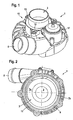
- FIG. 1 shows a perspective view of a plastic compressor housing 1.
- the plastic compressor housing 1 has a Fluidansaugstutzen in the form of an air intake 3.
- the air sucked in via the air intake 3 can be compressed by means of a radial compressor wheel (not shown) and exits the plastic compressor housing 1 via a fluid outlet nozzle in the form of an air outlet nozzle 5.
- FIG. 2 which is a plan view of the underside of the plastic compressor housing 1, it can be seen that the plastic compressor housing 1 consists of a first housing part 7, which is formed by a first single element in the form of an inner part 7a and a second single element in the form of an upper shell 7b, and a second housing part which is integrally formed in the form of a lower shell 9.
- these housing parts 7, 7a, 7b, 9 by encapsulation with a Duroplast stresses 11 an integral component with high structural strength.
- a third housing part 15 which is also referred to as an attachment, on which by the housing part. 7 , the lower shell 9 and the thermoset body 11 formed member attached.
- a first connecting element for connecting the air intake 3 with an air intake hose not shown.
- a valve arrangement in the form of a diverter valve 17, the function of which will be explained in detail later, is provided in the plastic compressor housing 1 by the third housing part 15.
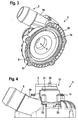
- FIG. 3 is a perspective view of the underside of the plastic compressor housing 1 is shown.
- the thermoset body 11 and thus the first housing part 7 and the second housing part 9 of the plastic compressor housing 1 hood-like covered by a thermoplastic 19.
- This thermoplastic 19 is produced in particular by extrusion coating.
- the thermoplastic 19 ensures that under extreme loads, as can occur in particular in a containment test, the greatest possible safety of the plastic compressor housing 1 is ensured.
- destruction of the integrity of the thermoset housing part 7, the lower shell 9 and the Duroplast stresses 11 may occur, for example, when a rotating in the plastic compressor housing 1 Radialver Togetherrrad comes into contact with the first housing part 7 or the lower shell 9.
- the thermoplastic 19 is ensured in such a case that no fragments of the housing part 7, the inner part 7a, the upper shell 7b, the lower shell 9 or the Duroplast stressess 11 can escape from the plastic compressor housing 1.
- FIG. 4 is a side view of the plastic compressor housing 1 of FIGS. 1 to 3 shown.
- the diverter valve 17 has a cover 21 which is fastened by screws 23 to the third housing part 15.
- the cover 21 and / or the third housing part 15 preferably comprise or comprise a glass fiber reinforced thermoplastic material.
- a connecting piece 25 is also arranged for connection of a vacuum supply, not shown.
- FIG. 5 shows a plan view of the top of the plastic compressor housing 1 of FIGS. 1 to 4 .
- the reference numerals correspond to those of FIGS. 1 to 4 ,
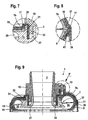
- FIG. 6 is a cross-sectional view of the plastic compressor housing 1 along the section line AA of FIG. 5 shown.
- the relative positions of the first housing part 7, which is formed by an inner part 7a and an upper shell 7b, and the second housing part, which is formed by the lower shell 9, can be seen.
- the housing part 7 and the lower shell 9, each consisting of a thermoset material are encapsulated with the thermoset body 11.
- the Duroplast stresses 11 is hood-like surrounded by the thermoplastic 19.
- the inner part 7a is formed from its contour forth so that a first recess 27 is formed in the inner part 7a.
- FIG. 7 a detail view of section B of the FIG. 6 can be seen, the encapsulation of the housing part 7 in the form of the Duroplast stressess 11 extends into the recess 27 into it.
- the thermoplastic 19 also extends into the recess 27. As in particular in FIG. 6 is shown, this expansion of the thermoplastic 19 leads to the formation of a so-called double barge.
- thermoset material in the form of the inner part 7a, the upper shell 7b, the lower shell 9 and the Duroplast stresses 11 both in the direction of an axis of symmetry S of the plastic compressor housing 1 and in one direction is stopped radially outward on the thermoplastic 19 from the symmetry axis S.
- thermoset fragments are prevented from entering the air intake 3 from the direction of the compressor passage 29 through the inner part 7a.
- the safety of the plastic compressor housing 1 also in the case in which the structural integrity of one of the thermoset elements of the plastic compressor housing 1 is destroyed, increased.
- this Doppelbariere leads to the formation of improved fluid tightness, so that it is effectively prevented that in a gas entrained liquids, such as oil, can escape from the plastic compressor housing 1.
- the recess 27 also acts as a second recess, since the third housing part 15 is at least partially received in the recess 27.
- the inner part 7a has a sealing element 31.
- the sealing member 31 is formed in the form of a groove in which an unillustrated sealing member is arranged in the form of an O-ring.
- the third housing part 15 has a sealing element 33 in the form of a groove in which a sealing element, not shown, such as an O-ring, is arranged.
- a sealing element not shown, such as an O-ring
- the inner part 7a has a first anchoring element in the form of an undercut 35.
- the undercut 35 ensures that the inner part 7a is anchored in the thermoset body 11 in an encapsulation of the first housing part 7 with the thermoset body 11.
- FIG. 8 representing a detail view of section C of FIG. 6 shows, also have the upper shell 7b and the lower shell 9 anchoring elements.
- a survey 37 is formed at the end edge of the upper shell 7b, while the lower shell 9 has an elevation 39 at one end edge.
- the thermoset body 11 also has a second anchoring element in the form of an undercut 41.
- a secure frictional or positive holding of the thermoplastic 19 on the thermoset body 11 is achieved.
- the anchoring elements 35, 37, 39 and 41 act as anchor points for the inner part 7a, the upper shell 7b and the lower shell 9 and the thermoplastic 19 on the Duroplast stresses eleventh
- FIG. 9 is a cross-sectional view of the plastic compressor housing 1 along the section line DD of FIG. 5 shown.
- the inner part 7a provides a Schneckeninnenkontur for the compressor passage 29.
- FIG. 11 shows a detailed view of the section F of FIG. 9 , How out FIG. 11 can be seen, the third housing part 15 is fastened by means of fastening elements in the form of screws 13 to the Duroplast Sciences 11.
- the thermoset body 11 has a blind bore 43.
- the blind bore 43 forms a fastening means in which the self-tapping screw engages.
- a direct contact of the third housing part 15 with the thermoset body 11 is ensured in the region of the first fastening means in the form of the blind bore 43, since in this area the thermoplastic 19 does not cover the thermoset body 11. This ensures that there is no relative movement between the third housing part 15 and the Duroplast emotions 11.
- the diverter valve 17 has a valve chamber 45, which is limited by the third housing part 15 substantially. Through an opening 47 in the third housing part 15 and in the upper shell 7b of the valve chamber 45 is in fluid communication with the compressor passage 29 in the region of the air outlet nozzle 5.
- the upper shell 7b has a sealing member 49 in the form of a recess, in which a sealing element, not shown, is arranged in the form of an O-ring.
- the opening 47 can be closed by means of a membrane 51, which may in particular comprise a rubber material. By applying a negative pressure via the connecting piece 25, a negative pressure can be generated within a membrane space 53, through which a movement of the membrane 51 takes place whereby the opening 47 is opened.
- the membrane against the force of a spring element, not shown, which forces the diaphragm 51 in the direction of the opening 47 moves.
- an actuating element is arranged, which is mechanically connected to the diaphragm 51, wherein a movement of the actuating element and thus the diaphragm 51 for releasing the opening 47 is caused by a means of the connecting piece 25 applied negative pressure.
- the membrane 51 may be in operative connection with, in particular comprise, at least one reinforcing element, such as a backing pad. Both the actuating element and the spring element can find attack on the reinforcing element.
- the third housing part 15 is an in FIG. 10 Not shown connecting line formed, which connects the valve chamber 45 with the air intake 3.
- a diverter valve is used in particular in turbochargers for gasoline engines, to prevent that at a closed throttle by the turbocharger an excessive charge air pressure is generated.
- diverter valve 17 which is designed as a vacuum valve
- the invention can of course be performed with a designed as a pressure relief valve diverter valve 17.
- a screw or an inner part 7a ' which can be formed from a thermoset body by injection molding, is provided.
- a lower shell 9 ' is arranged around the inner part 7a'.
- the lower shell 9 ' is formed of a thermosetting material and can be produced in an injection molding process due to their comparatively simple cross-sectional shape.
- a first housing part 7 ' by merging the inner part 7a' with an upper shell 7b 'completed.
- the air outlet nozzle 5 ' is at least partially provided by the upper shell 7b' and in FIG.
- FIG. 14 is the arrangement of the opening 47 'to provide a fluid connection to a compressor duct shown. Furthermore, it is off FIG. 14 it can be seen that those parts of the inner part 7a ', which include the undercut 35', are arranged so that they protrude from the upper shell 7b '.
- a subsequent encapsulation of the first housing part 7 'and the second housing part in the form of the lower shell 9' with a thermoset body 11 ' as in FIG. 15 is shown, it is achieved that not only the upper shell 7b 'and the lower shell 9', but also the inner part 7a 'are anchored to the Duroplast stresses 11' by all housing parts or individual elements with the Duroplast stresses 11 'are in contact.
- the Duroplast Sciences 11 ' is covered by hood-like encapsulation of the thermoplastic 19'.
- the end of the thermoset body 11 'formed by the air outlet nozzle 5' is not covered by the thermoplastic body 19 '.
- this region of the Duroplast stressess 11 ' may be covered with thermoplastic or even another Fluidleitelement, such as a filter element, connected to the air outlet nozzle 5' and are covered by the thermoplastic 19 'at least partially.
- a secure connection of the plastic compressor housing 1 ' can be achieved with the fluid guide in a simple manner.
- the thermoplastic 19 'does not cover the thermoset body 11' in the area of the screws 13 '. This ensures that a secure attachment of the third housing part 15 'on the Duroplast stresses 11' is achieved.
- FIG. 18 is a cross-sectional view of the plastic compressor housing 1 'shown. Out FIG. 18 Further details of the third housing part 15 'of the plastic compressor housing 1' can be seen. Thus, the third housing part 15 'on a connecting line 57'. This connecting line 57 'is on the one hand with the valve chamber 45' and on the other hand with the air intake 3 'in fluid communication. In the case where the diaphragm 51 'releases the port 47', a secondary circuit between the air exhaust port 5 'and the air intake port 3' is opened in this way. This is due to the fact that the opening 47 'in the region of the air outlet nozzle 5' in the compressor passage 29 'opens.
- the third housing part 15 'further comprises a connecting line 59', which the valve chamber 45 'with the environment of the plastic compressor housing 1 'connects, on.
- connection lines 57 'or 59' By a suitable closure of one of the connecting lines 57 'or 59' via a closure element, not shown, an expansion of the compressed charge air in the surrounding atmosphere or the air intake 3 'can be achieved via the diverter valve 17'. Also, the output of the connecting line 59 'with another component, such as another fluid line or a filter or damper, are connected.
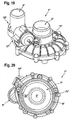
- FIG. 19 3 shows a third embodiment of a plastic compressor housing 1 "according to the invention.
- Those elements of the plastic compressor housing 1" which functionally correspond to those of the plastic compressor housing 1 or the plastic compressor housing 1 'bear the same reference numerals, but with double coating.
- the plastic compressor housing 1 In comparison to the plastic compressor housings 1, 1 ', the plastic compressor housing 1 "a modified arrangement of the air outlet nozzle 5", which results from a geometrically altered shape of the first housing part 7 "and the second housing part 9".
- the air outlet nozzle 5 is also partially formed by the third housing part 15" and has an axis of symmetry which is substantially parallel to the axis of symmetry of the air intake 3 ".
- the plastic compressor housing 1 Similar to the plastic compressor housings 1, 1 ', the plastic compressor housing 1 "according to the FIGS. 19 and 20 a first housing part 7 ", which is formed by individual elements in the form of an inner part 7a" and an upper shell 7b. "Furthermore, the plastic compressor housing 1" comprises a second housing part which is substantially integrally formed in the form of a lower shell 9 " Housing part and the second housing part of the plastic compressor housing 1 "are formed of a thermoset material and / or comprise a thermoset material.
- FIGS. 21 and 22 show perspective views of the plastic compressor housing 1 ", it can be seen, the first housing part 7" and the second housing part in the form of the lower shell 9 "with a thermoplastic body 20" overmolded.
- the third housing part 15 is fastened on the thermoplastic body 20" by means of a third connecting element in the form of screws 13 " FIG. 22 shown that the air outlet nozzle 5 "is formed substantially by the third housing part 15".
- the diverter valve 17 is completed by a cover 21" secured by screws 23 "to the third housing part 15".
- In the lid 21 " is a connection piece 25" formed for a pressure control.
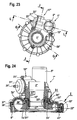
- FIG. 23 is a perspective view of the plastic compressor housing 1 "shown FIGS. 24 to 29 , which show sectional views along the sections GG, JJ and LL and respective detail views along sections H, I, K of the sectional views, the manufacture and construction of the plastic compressor housing 1 "will be explained in more detail below.
- FIG. 24 is a cross-sectional view of the plastic compressor housing 1 '' along the section GG of FIG. 23 shown.
- a first housing part 7 is formed by an inner part 7a" and an upper shell 7b ".
- a second housing part is formed by a lower shell 9".
- the first housing part 7 "and the second housing part 9" are not encapsulated with a thermoset body.
- the first and the second housing part are connected to one another in the production of the plastic compressor housing 1 "via a fourth connecting element in the form of a screw connection 22".
- thermoplastic body 20 "covers the anchoring elements formed in the first and second housing parts so as to form a strong bond between the housing parts.”
- the thermoplastic body 20 encloses "protrusions 37", 39 “, enters undercuts 41" and depressions 27 ".
- the thermoplastic body 20 also encloses "undercuts 35".
- the individual elements 7a “, 7b” and 9 are positively and non-positively connected to one another via the thermoplastic body 20 or anchored in the thermoplastic body 20." Since the thermoplastic body 20 "also enters a recess 27" or this A fragment of a single element or of a compressor wheel, not shown, entering from the compressor duct 29 "into the inner part 7a” could indeed lead to a destruction of the inner part 7a ", but the broken piece would result in the plastic compressor housing 1" the formed in the recess 27 a "formed thermoplastic barrier.
- thermoplastic body 20 circulating in a gap 24" between the inner part 7a “and the upper shell 7b” occurs, it also comes to a cohesive connection of the inner part 7a “and the upper shell 7b” on the thermoplastic body 20 ".
- the third housing part 15 which is in the form of an attachment, via screws 13 "on the thermoplastic body 20" or the first housing part 7 “and the second housing part 9" be attached.
- FIG. 25 is a detail view of the section H of the FIG. 24 shown. From the FIG. 25 in particular it can be seen how the thermoplastic body 20 "engages in the undercuts 35" for anchoring, the recess 27 “fills to form the double barrier and that sealing elements 31" and 33 "between the inner part 7a” and the upper shell 7b “on the one hand and the thermoplastic body
- the sealing elements 31 "and 33” are in the form of O-rings
- the outer contour of the inner part 7a matcheses the inner contour of the upper shell 7b” by a displacement to avoid these elements to each other in an encapsulation of the thermoplastic body 20 ".
- FIG. 26 is a detail view of the section I of the FIG. 24 shown. It is easy to see how the upper shell 7b "and the lower shell 9" are non-positively connected to one another via the screw connections 22. This ensures that the upper shell 7b “can not move relative to the lower shell 9" when the thermoplastic body 20 " is produced by encapsulation. Furthermore, in FIG. 26 to recognize another sealing element 32 ", which ensures a seal between the upper shell 7b" and the lower shell 9 ", so that in particular fluids from the compressor duct 29" can not escape even under extreme loads.
- FIG. 27 is a cross-sectional view of the plastic compressor housing 1 "along the section JJ of FIG. 23 shown.
- the air intake 3 is connected to a valve space 45" via a connecting line 57.
- a membrane 51 is arranged in the valve space 45" on the other side in the air intake 3 ", as in particular in FIG. 24 shown.
- FIG. 29 is opened and closed by the diaphragm 51 "a diverter valve 17".
- a connection of the air intake 3 " is made with the air outlet nozzle 5". This takes place in particular in the states in which a throttle valve of the engine is closed and an excessively high pressure is created in the air outlet port 5 " FIG. 27 can still be seen, serve the screws 23 "for fixing a lid 21" on the third housing part 15 ".
- FIG. 28 is a detail view of the section K of FIG. 27 shown.
- the third housing part 15 is connected via screws 13" with the first and second housing part. But how the FIG. 28 can be seen, covers the thermoplastic body 20 "the upper shell 7b" not completely, so that the third housing part 15 "directly on the upper shell 7b", the thermoset material rests, rests. As a result, a relative movement of the third housing part 15, which preferably comprises a fiber-reinforced thermoplastic, "relative to the upper shell 7b" is avoided.
- FIG. 29 which is a cross-sectional view of the plastic compressor housing 1 "along the section LL of FIG. 23 represents the operation of the diverter valve 17 "supplemented FIG. 29 can be seen, the valve chamber 45 "in which the connecting line 57" to the air intake 3 "opens, from an opening 47", which opens into the air outlet nozzle 5 ", separated by means of the membrane 51".
- the connecting piece 25 By applying a corresponding pressure signal to the connecting piece 25 ", the diaphragm 51" against a not shown spring element in the direction of the cylinder chamber 55 "are moved and so a connection between the connecting line 57" and the opening 47 “and thus a connection between the air intake. 3
- a bypass line is formed around the compressor, so that the air from the air intake 3 "directly into the air outlet pipe 5" can occur.
- the third housing part 15 at least partially forms a functional component of the plastic compressor housing 1" in the form of the air outlet nozzle 5. Furthermore, the third housing part 15 "also forms another functional component of the compressor formed by the plastic compressor housing 1" the diverter valve 17 "formed. Other functional components of the compressor can also be at least partially formed by the first housing part, the second housing part or the third housing part.
- a so-called control can is formed in one of the housing parts, at least in certain areas.
- a control socket is understood to mean an element which is used to regulate the pressure of the turbine side of the compressor Temperatures may be present, it is preferred that such a control box is placed on the compressor side of the compressor and a pressure control on the turbine side is achieved via a mechanical element connected to the control box integrate leading functional elements of a compressor in the plastic compressor housing at least partially without the manufacturing process is complicated or the stability of the plastic compressor housing including l Eidet.
Landscapes
- Engineering & Computer Science (AREA)
- Mechanical Engineering (AREA)
- General Engineering & Computer Science (AREA)
- Manufacturing & Machinery (AREA)
- Structures Of Non-Positive Displacement Pumps (AREA)
- Compressor (AREA)
- Laminated Bodies (AREA)
Applications Claiming Priority (1)
| Application Number | Priority Date | Filing Date | Title |
|---|---|---|---|
| DE102007027282A DE102007027282B3 (de) | 2007-06-11 | 2007-06-11 | Kunststoffverdichtergehäuse und Verfahren zur Herstellung eines Kunststoffverdichtergehäuses |
Publications (3)
| Publication Number | Publication Date |
|---|---|
| EP2003343A2 true EP2003343A2 (fr) | 2008-12-17 |
| EP2003343A3 EP2003343A3 (fr) | 2009-05-27 |
| EP2003343B1 EP2003343B1 (fr) | 2011-05-25 |
Family
ID=39816744
Family Applications (1)
| Application Number | Title | Priority Date | Filing Date |
|---|---|---|---|
| EP08010316A Not-in-force EP2003343B1 (fr) | 2007-06-11 | 2008-06-06 | Boîtier de turbo-compresseur en matière synthétique et son procédé de fabrication |
Country Status (4)
| Country | Link |
|---|---|
| US (1) | US8419359B2 (fr) |
| EP (1) | EP2003343B1 (fr) |
| AT (1) | ATE511023T1 (fr) |
| DE (1) | DE102007027282B3 (fr) |
Cited By (3)
| Publication number | Priority date | Publication date | Assignee | Title |
|---|---|---|---|---|
| US7862298B2 (en) | 2006-02-27 | 2011-01-04 | Woco Industrietechnik Gmbh | Centrifugal compressor housing |
| CN102414450A (zh) * | 2009-04-22 | 2012-04-11 | 帝斯曼知识产权资产管理有限公司 | 径流式压缩机的塑料外壳 |
| US8342800B2 (en) | 2007-02-27 | 2013-01-01 | Woco Industrietechnik Gmbh | Plastic compressor housing and method for producing same |
Families Citing this family (22)
| Publication number | Priority date | Publication date | Assignee | Title |
|---|---|---|---|---|
| DE102009009389B4 (de) | 2009-02-18 | 2011-03-24 | Woco Industrietechnik Gmbh | Verdichtergehäuse, Verdichter umfassend ein solches Verdichtergehäuse und Verfahren zur Herstellung eines Verdichtergehäuses |
| FR2949517B1 (fr) * | 2009-08-25 | 2011-10-21 | Snecma | Carter de turbomachine a etancheite renforcee |
| DE102010064025A1 (de) * | 2010-12-23 | 2012-06-28 | Abb Turbo Systems Ag | Berstschutz |
| DE102011088032A1 (de) * | 2011-12-08 | 2013-06-13 | Bosch Mahle Turbo Systems Gmbh & Co. Kg | Ladeeinrichtung |
| US20140026993A1 (en) * | 2012-07-30 | 2014-01-30 | Hamilton Sundstrand Corporation | Cabin air compressor heat housing |
| DE112015000330T5 (de) * | 2014-02-05 | 2016-11-03 | Borgwarner Inc. | Aufladevorrichtung |
| DE202014102996U1 (de) | 2014-07-01 | 2015-10-06 | Woco Industrietechnik Gmbh | Elektromagnetisch angetriebener Verdichter |
| JP6322121B2 (ja) * | 2014-10-29 | 2018-05-09 | 株式会社オティックス | ターボチャージャ用のコンプレッサ構造 |
| KR102010337B1 (ko) * | 2014-12-04 | 2019-08-13 | 한화파워시스템 주식회사 | 압축 장치용 하우징 및 압축 장치 |
| US9803651B2 (en) * | 2015-01-06 | 2017-10-31 | Bullseye Power, LLC | Turbocharger compressor cover with convertible outlet connection |
| CN106968984B (zh) * | 2015-12-11 | 2020-10-23 | 松下知识产权经营株式会社 | 涡轮机 |
| CN109154306B (zh) * | 2016-03-31 | 2021-01-26 | 三菱重工发动机和增压器株式会社 | 径向压缩机的壳体及径向压缩机 |
| US10690144B2 (en) * | 2017-06-27 | 2020-06-23 | Garrett Transportation I Inc. | Compressor housings and fabrication methods |
| US10519974B2 (en) | 2017-10-17 | 2019-12-31 | Borgwarner Inc. | Multi-piece compressor housing for a turbocharger |
| US10690145B2 (en) | 2018-04-27 | 2020-06-23 | Air-Tec Innovations, LLC | Turbo housing |
| JP2019203446A (ja) * | 2018-05-23 | 2019-11-28 | 株式会社オティックス | ターボチャージャ用のコンプレッサハウジング及びその製造方法 |
| USD902961S1 (en) * | 2019-03-01 | 2020-11-24 | Savant Holdings LLC | Compressor housing |
| US10927702B1 (en) | 2019-03-30 | 2021-02-23 | Savant Holdings LLC | Turbocharger or turbocharger component |
| JP2021105385A (ja) * | 2019-12-27 | 2021-07-26 | 三菱重工エンジン&ターボチャージャ株式会社 | コンプレッサカバーおよび該コンプレッサカバーを備える遠心圧縮機 |
| USD900163S1 (en) * | 2020-02-20 | 2020-10-27 | Savant Holdings LLC | Compressor housing |
| US12480425B2 (en) * | 2024-01-26 | 2025-11-25 | Hamilton Sundstrand Corporation | Rotor containment structure |
| CN120312560B (zh) * | 2025-06-18 | 2025-08-26 | 宁波甬微集团有限公司 | 一种压缩机组件和制造方法 |
Citations (3)
| Publication number | Priority date | Publication date | Assignee | Title |
|---|---|---|---|---|
| US6193463B1 (en) | 1999-06-30 | 2001-02-27 | Alliedsignal, Inc. | Die cast compressor housing for centrifugal compressors with a true volute shape |
| DE10260042A1 (de) | 2002-12-19 | 2004-07-08 | Volkswagen Ag | Turbolader-Gehäuse |
| DE10314209B3 (de) | 2003-03-28 | 2004-12-09 | Woco Industrietechnik Gmbh | Gehäuse für einen Radialverdichter und Verfahren zum Herstellen des Gehäuses |
Family Cites Families (41)
| Publication number | Priority date | Publication date | Assignee | Title |
|---|---|---|---|---|
| US1467254A (en) * | 1921-02-21 | 1923-09-04 | Tarbet Albert | Self-locking milk-can cover |
| DE1985256U (de) * | 1966-05-12 | 1968-05-09 | Metal Containers Ltd | Geteilter verschlussring zum befestigen eines deckels an einem behaelterkoerper. |
| DE2706110C3 (de) * | 1977-02-14 | 1981-07-09 | Aktiengesellschaft Kühnle, Kopp & Kausch, 6710 Frankenthal | Verdichtergehäuse vorzugsweise für Abgasturbolader |
| JPS55118845A (en) | 1979-03-06 | 1980-09-12 | Matsushita Electric Works Ltd | Molding method of double layer molded article |
| JPS55118844A (en) | 1979-03-06 | 1980-09-12 | Matsushita Electric Works Ltd | Double layer molded article and its manufacture |
| JPS5856821A (ja) | 1981-09-30 | 1983-04-04 | Matsushita Electric Works Ltd | 多層成形方法 |
| DE3424661A1 (de) | 1984-07-05 | 1986-01-16 | MTU Motoren- und Turbinen-Union München GmbH, 8000 München | Einlaufbelag einer stroemungsmaschine |
| US4867641A (en) * | 1986-09-12 | 1989-09-19 | Kabushiki Kaisha Daikin Seisakusho | Outer wall structure of a torque converter and others |
| US5209461A (en) * | 1990-07-23 | 1993-05-11 | Ltv Energy Products Company | Elastomeric torsional spring having tangential spokes with varying elastic response |
| US5257904A (en) * | 1991-01-18 | 1993-11-02 | Sullivan John T | Volute housing for a centrifugal fan, blower or the like |
| DE9101683U1 (de) | 1991-02-14 | 1992-06-11 | Schemm GmbH, 5952 Attendorn | Spannring |
| US5219461A (en) * | 1992-04-28 | 1993-06-15 | Baker Hughes Incorporated | Reinforced elastomer lining for pump casing and associated method of manufacture |
| GB2281941B (en) | 1993-09-15 | 1996-05-08 | Rolls Royce Plc | Containment structure |
| DE4438750A1 (de) * | 1994-10-29 | 1996-05-02 | Pierburg Gmbh | Elektrisch angetriebene Luftpumpe |
| JP4031062B2 (ja) * | 1995-08-11 | 2008-01-09 | 株式会社荏原製作所 | プラスチック製部品及びその製造方法 |
| EP0850361B1 (fr) | 1995-09-13 | 2001-03-21 | Siemens Aktiengesellschaft | Compresseur de canal lateral |
| DE19712850A1 (de) * | 1997-03-27 | 1998-10-01 | Bosch Gmbh Robert | Vorrichtung zum Steuern eines Schubumluftventils |
| DE19720286A1 (de) | 1997-05-15 | 1998-11-19 | Winter Gmbh | Gehäuse mit einem unregelmäßigen Hohlraum und Verfahren zur Herstellung eines derartigen Gehäuses |
| DE19750516A1 (de) | 1997-11-14 | 1999-05-20 | Asea Brown Boveri | Abreibbare Dichtung |
| WO1999064747A1 (fr) | 1998-06-11 | 1999-12-16 | Resmed Limited | Logement pour helice centrifuge |
| DE69830204T2 (de) * | 1998-09-11 | 2006-02-16 | Peter John King | Flüssigkeitspumpen |
| JP3985855B2 (ja) * | 1999-01-19 | 2007-10-03 | 株式会社荏原製作所 | 樹脂製ケーシング |
| JP4136299B2 (ja) | 2000-09-12 | 2008-08-20 | キヤノン株式会社 | 合成樹脂製の部品結合体 |
| DE10054855A1 (de) | 2000-11-06 | 2002-05-08 | Abb Patent Gmbh | Elektrisches Installationsgerät |
| DE10103669B4 (de) * | 2001-01-27 | 2004-07-29 | Ksb Ag | Verfahren zur Herstellung eines mit Kunststoff überzogenen Gußstücks |
| DE10112764A1 (de) | 2001-03-16 | 2002-09-19 | Mann & Hummel Filter | Radialverdichter |
| US6823624B2 (en) * | 2001-07-17 | 2004-11-30 | S.I.T., Inc. | Plastic article with protuberance |
| DE10220573C1 (de) * | 2002-05-08 | 2003-07-03 | Mtu Friedrichshafen Gmbh | Abgasturbolader |
| US6652222B1 (en) * | 2002-09-03 | 2003-11-25 | Pratt & Whitney Canada Corp. | Fan case design with metal foam between Kevlar |
| US20040145092A1 (en) * | 2003-01-24 | 2004-07-29 | Mccollum Robert P. | Method of making a composite molded article |
| DE102004041439A1 (de) | 2004-08-27 | 2006-03-02 | Atlas Copco Energas Gmbh | Turbomaschine zur Expansion oder Verdichtung eines gas- oder dampfförmigen Fluids |
| DE202004019366U1 (de) | 2004-12-15 | 2006-04-20 | Nash_Elmo Industries Gmbh | Verdichter, insbesondere Seitenkanalverdichter |
| US7246990B2 (en) | 2004-12-23 | 2007-07-24 | General Electric Company | Composite fan containment case for turbine engines |
| US7254948B2 (en) * | 2005-02-21 | 2007-08-14 | Cummins Inc. | Boost wastegate device for EGR assist |
| US7478532B2 (en) * | 2005-11-07 | 2009-01-20 | Honeywell International, Inc. | Turbocharger containment shield |
| DE102005055200A1 (de) * | 2005-11-19 | 2007-05-24 | Mtu Aero Engines Gmbh | Verfahren zum Herstellen eines Einlaufbelags |
| DE102006009054B4 (de) * | 2006-02-27 | 2007-11-22 | Woco Industrietechnik Gmbh | Gehäuse für Radialverdichter |
| DE102006010461B3 (de) | 2006-03-03 | 2007-10-25 | Woco Industrietechnik Gmbh | Kunststoffverdichtergehäuse |
| DE102007009781B4 (de) | 2007-02-27 | 2009-09-17 | Woco Industrietechnik Gmbh | Kunststoffverdichtergehäuse sowie Verfahren zu dessen Herstellung |
| DE102007054899A1 (de) | 2007-11-15 | 2009-05-20 | Woco Industrietechnik Gmbh | Verdichtergehäuse mit Kunststoffkörper und Metall-Manschette sowie Verfahren zu dessen Herstellung |
| DE102008008981A1 (de) | 2008-02-13 | 2009-08-20 | Woco Industrietechnik Gmbh | Klemmspange insbesondere für ein Verdichtergehäuse |
-
2007
- 2007-06-11 DE DE102007027282A patent/DE102007027282B3/de not_active Expired - Fee Related
-
2008
- 2008-06-06 AT AT08010316T patent/ATE511023T1/de active
- 2008-06-06 EP EP08010316A patent/EP2003343B1/fr not_active Not-in-force
- 2008-06-11 US US12/137,500 patent/US8419359B2/en not_active Expired - Fee Related
Patent Citations (3)
| Publication number | Priority date | Publication date | Assignee | Title |
|---|---|---|---|---|
| US6193463B1 (en) | 1999-06-30 | 2001-02-27 | Alliedsignal, Inc. | Die cast compressor housing for centrifugal compressors with a true volute shape |
| DE10260042A1 (de) | 2002-12-19 | 2004-07-08 | Volkswagen Ag | Turbolader-Gehäuse |
| DE10314209B3 (de) | 2003-03-28 | 2004-12-09 | Woco Industrietechnik Gmbh | Gehäuse für einen Radialverdichter und Verfahren zum Herstellen des Gehäuses |
Cited By (4)
| Publication number | Priority date | Publication date | Assignee | Title |
|---|---|---|---|---|
| US7862298B2 (en) | 2006-02-27 | 2011-01-04 | Woco Industrietechnik Gmbh | Centrifugal compressor housing |
| US8342800B2 (en) | 2007-02-27 | 2013-01-01 | Woco Industrietechnik Gmbh | Plastic compressor housing and method for producing same |
| CN102414450A (zh) * | 2009-04-22 | 2012-04-11 | 帝斯曼知识产权资产管理有限公司 | 径流式压缩机的塑料外壳 |
| CN102414450B (zh) * | 2009-04-22 | 2014-04-02 | 帝斯曼知识产权资产管理有限公司 | 径流式压缩机的塑料外壳 |
Also Published As
| Publication number | Publication date |
|---|---|
| EP2003343B1 (fr) | 2011-05-25 |
| US8419359B2 (en) | 2013-04-16 |
| DE102007027282B3 (de) | 2008-11-13 |
| US20080304960A1 (en) | 2008-12-11 |
| EP2003343A3 (fr) | 2009-05-27 |
| ATE511023T1 (de) | 2011-06-15 |
Similar Documents
| Publication | Publication Date | Title |
|---|---|---|
| EP2003343B1 (fr) | Boîtier de turbo-compresseur en matière synthétique et son procédé de fabrication | |
| DE3743594C2 (fr) | ||
| EP1051566B1 (fr) | Corps de papillon des gaz | |
| EP1830071A2 (fr) | Boîtier de compresseur en plastique | |
| DE102007041949B3 (de) | Befestiger | |
| DE3816608A1 (de) | Hydraulikzylinder | |
| EP3070209B1 (fr) | Corps de robinetterie pour une armature sanitaire et procede de fabrication | |
| EP0908651B1 (fr) | Dispositif de clapet de non-retour | |
| EP1514031A1 (fr) | Liaison par vis comportant un col d'etancheite | |
| DE102004062071A1 (de) | Nockenwellenversteller für eine Brennkraftmaschine | |
| WO2020208087A1 (fr) | Joint d'étanchéité repliable avec un contour d'étanchéité continu | |
| EP1200722A1 (fr) | Dispositif d'etranglement a volet destine au montage dans une jonction a brides | |
| DE10335261A1 (de) | Verdichterrad und/oder Turbinenrad für eine Sekundärluftfördereinrichtung | |
| DE102015008328A1 (de) | Filteranschlusseinrichtung, Filtereinrichtung und Verbindungsvorrichtung zur Verbindung eines Filters mit einer Filteranschlusseinrichtung | |
| DE102006024767A1 (de) | Verfahren und Vorrichtung zum Verbinden eines Kunststoffdeckels mit einem Metallgehäuse | |
| DE102007048852A1 (de) | Verdichtergehäuse für den Verdichter eines Turboladers und Verfahren zur Herstellung eines solchen Verdichtergehäuses | |
| DE102015224440A1 (de) | Zylinderkopfhaube | |
| DE102018116785B3 (de) | Baueinheit zur Aufnahme eines unter wechselndem Druck stehenden Fluids, insbesondere im Ansaugtrakt einer Brennkraftmaschine | |
| DE102012104479B4 (de) | Verdichtergehäuse, insbesondere Turboladergehäuse, und Verfahren zur Herstellung eines Verdichtergehäuses | |
| DE102020116731A1 (de) | Pumpe mit befestigter Dichtung | |
| DE202006011672U1 (de) | Zylinderkopfhaube | |
| EP0690956A1 (fr) | Procede de fabrication d'un couvercle coule en metal leger et couvercle ainsi obtenu | |
| DE102005046065A1 (de) | Stromventil zum Drosseln hydraulischer Druckmittel | |
| DE20103393U1 (de) | Rasteinrichtung für Getriebeteile | |
| WO2012013352A1 (fr) | Pré-ébauche pour une partie d'habillage intérieur d'un véhicule et une partie d'habillage intérieur |
Legal Events
| Date | Code | Title | Description |
|---|---|---|---|
| PUAI | Public reference made under article 153(3) epc to a published international application that has entered the european phase |
Free format text: ORIGINAL CODE: 0009012 |
|
| AK | Designated contracting states |
Kind code of ref document: A2 Designated state(s): AT BE BG CH CY CZ DE DK EE ES FI FR GB GR HR HU IE IS IT LI LT LU LV MC MT NL NO PL PT RO SE SI SK TR |
|
| AX | Request for extension of the european patent |
Extension state: AL BA MK RS |
|
| PUAL | Search report despatched |
Free format text: ORIGINAL CODE: 0009013 |
|
| AK | Designated contracting states |
Kind code of ref document: A3 Designated state(s): AT BE BG CH CY CZ DE DK EE ES FI FR GB GR HR HU IE IS IT LI LT LU LV MC MT NL NO PL PT RO SE SI SK TR |
|
| AX | Request for extension of the european patent |
Extension state: AL BA MK RS |
|
| RIC1 | Information provided on ipc code assigned before grant |
Ipc: B29C 45/14 20060101ALI20090422BHEP Ipc: F04D 29/42 20060101ALI20090422BHEP Ipc: F04D 29/02 20060101AFI20081015BHEP |
|
| 17P | Request for examination filed |
Effective date: 20091111 |
|
| AKX | Designation fees paid |
Designated state(s): AT BE BG CH CY CZ DE DK EE ES FI FR GB GR HR HU IE IS IT LI LT LU LV MC MT NL NO PL PT RO SE SI SK TR |
|
| GRAP | Despatch of communication of intention to grant a patent |
Free format text: ORIGINAL CODE: EPIDOSNIGR1 |
|
| GRAS | Grant fee paid |
Free format text: ORIGINAL CODE: EPIDOSNIGR3 |
|
| GRAA | (expected) grant |
Free format text: ORIGINAL CODE: 0009210 |
|
| AK | Designated contracting states |
Kind code of ref document: B1 Designated state(s): AT BE BG CH CY CZ DE DK EE ES FI FR GB GR HR HU IE IS IT LI LT LU LV MC MT NL NO PL PT RO SE SI SK TR |
|
| REG | Reference to a national code |
Ref country code: GB Ref legal event code: FG4D Free format text: NOT ENGLISH |
|
| REG | Reference to a national code |
Ref country code: CH Ref legal event code: EP |
|
| REG | Reference to a national code |
Ref country code: IE Ref legal event code: FG4D Free format text: LANGUAGE OF EP DOCUMENT: GERMAN |
|
| REG | Reference to a national code |
Ref country code: DE Ref legal event code: R096 Ref document number: 502008003649 Country of ref document: DE Effective date: 20110707 |
|
| REG | Reference to a national code |
Ref country code: NL Ref legal event code: VDEP Effective date: 20110525 |
|
| PG25 | Lapsed in a contracting state [announced via postgrant information from national office to epo] |
Ref country code: SE Free format text: LAPSE BECAUSE OF FAILURE TO SUBMIT A TRANSLATION OF THE DESCRIPTION OR TO PAY THE FEE WITHIN THE PRESCRIBED TIME-LIMIT Effective date: 20110525 Ref country code: HR Free format text: LAPSE BECAUSE OF FAILURE TO SUBMIT A TRANSLATION OF THE DESCRIPTION OR TO PAY THE FEE WITHIN THE PRESCRIBED TIME-LIMIT Effective date: 20110525 Ref country code: LT Free format text: LAPSE BECAUSE OF FAILURE TO SUBMIT A TRANSLATION OF THE DESCRIPTION OR TO PAY THE FEE WITHIN THE PRESCRIBED TIME-LIMIT Effective date: 20110525 Ref country code: NO Free format text: LAPSE BECAUSE OF FAILURE TO SUBMIT A TRANSLATION OF THE DESCRIPTION OR TO PAY THE FEE WITHIN THE PRESCRIBED TIME-LIMIT Effective date: 20110825 Ref country code: PT Free format text: LAPSE BECAUSE OF FAILURE TO SUBMIT A TRANSLATION OF THE DESCRIPTION OR TO PAY THE FEE WITHIN THE PRESCRIBED TIME-LIMIT Effective date: 20110926 |
|
| PG25 | Lapsed in a contracting state [announced via postgrant information from national office to epo] |
Ref country code: ES Free format text: LAPSE BECAUSE OF FAILURE TO SUBMIT A TRANSLATION OF THE DESCRIPTION OR TO PAY THE FEE WITHIN THE PRESCRIBED TIME-LIMIT Effective date: 20110905 Ref country code: SI Free format text: LAPSE BECAUSE OF FAILURE TO SUBMIT A TRANSLATION OF THE DESCRIPTION OR TO PAY THE FEE WITHIN THE PRESCRIBED TIME-LIMIT Effective date: 20110525 Ref country code: LV Free format text: LAPSE BECAUSE OF FAILURE TO SUBMIT A TRANSLATION OF THE DESCRIPTION OR TO PAY THE FEE WITHIN THE PRESCRIBED TIME-LIMIT Effective date: 20110525 Ref country code: GR Free format text: LAPSE BECAUSE OF FAILURE TO SUBMIT A TRANSLATION OF THE DESCRIPTION OR TO PAY THE FEE WITHIN THE PRESCRIBED TIME-LIMIT Effective date: 20110826 Ref country code: CY Free format text: LAPSE BECAUSE OF FAILURE TO SUBMIT A TRANSLATION OF THE DESCRIPTION OR TO PAY THE FEE WITHIN THE PRESCRIBED TIME-LIMIT Effective date: 20110525 Ref country code: IS Free format text: LAPSE BECAUSE OF FAILURE TO SUBMIT A TRANSLATION OF THE DESCRIPTION OR TO PAY THE FEE WITHIN THE PRESCRIBED TIME-LIMIT Effective date: 20110925 Ref country code: FI Free format text: LAPSE BECAUSE OF FAILURE TO SUBMIT A TRANSLATION OF THE DESCRIPTION OR TO PAY THE FEE WITHIN THE PRESCRIBED TIME-LIMIT Effective date: 20110525 |
|
| REG | Reference to a national code |
Ref country code: IE Ref legal event code: FD4D |
|
| PG25 | Lapsed in a contracting state [announced via postgrant information from national office to epo] |
Ref country code: MT Free format text: LAPSE BECAUSE OF FAILURE TO SUBMIT A TRANSLATION OF THE DESCRIPTION OR TO PAY THE FEE WITHIN THE PRESCRIBED TIME-LIMIT Effective date: 20110525 Ref country code: NL Free format text: LAPSE BECAUSE OF FAILURE TO SUBMIT A TRANSLATION OF THE DESCRIPTION OR TO PAY THE FEE WITHIN THE PRESCRIBED TIME-LIMIT Effective date: 20110525 |
|
| BERE | Be: lapsed |
Owner name: WOCO INDUSTRIETECHNIK G.M.B.H. Effective date: 20110630 |
|
| PG25 | Lapsed in a contracting state [announced via postgrant information from national office to epo] |
Ref country code: IE Free format text: LAPSE BECAUSE OF FAILURE TO SUBMIT A TRANSLATION OF THE DESCRIPTION OR TO PAY THE FEE WITHIN THE PRESCRIBED TIME-LIMIT Effective date: 20110525 Ref country code: EE Free format text: LAPSE BECAUSE OF FAILURE TO SUBMIT A TRANSLATION OF THE DESCRIPTION OR TO PAY THE FEE WITHIN THE PRESCRIBED TIME-LIMIT Effective date: 20110525 Ref country code: CZ Free format text: LAPSE BECAUSE OF FAILURE TO SUBMIT A TRANSLATION OF THE DESCRIPTION OR TO PAY THE FEE WITHIN THE PRESCRIBED TIME-LIMIT Effective date: 20110525 |
|
| PG25 | Lapsed in a contracting state [announced via postgrant information from national office to epo] |
Ref country code: DK Free format text: LAPSE BECAUSE OF FAILURE TO SUBMIT A TRANSLATION OF THE DESCRIPTION OR TO PAY THE FEE WITHIN THE PRESCRIBED TIME-LIMIT Effective date: 20110525 Ref country code: RO Free format text: LAPSE BECAUSE OF FAILURE TO SUBMIT A TRANSLATION OF THE DESCRIPTION OR TO PAY THE FEE WITHIN THE PRESCRIBED TIME-LIMIT Effective date: 20110525 Ref country code: SK Free format text: LAPSE BECAUSE OF FAILURE TO SUBMIT A TRANSLATION OF THE DESCRIPTION OR TO PAY THE FEE WITHIN THE PRESCRIBED TIME-LIMIT Effective date: 20110525 Ref country code: PL Free format text: LAPSE BECAUSE OF FAILURE TO SUBMIT A TRANSLATION OF THE DESCRIPTION OR TO PAY THE FEE WITHIN THE PRESCRIBED TIME-LIMIT Effective date: 20110525 |
|
| PG25 | Lapsed in a contracting state [announced via postgrant information from national office to epo] |
Ref country code: BE Free format text: LAPSE BECAUSE OF NON-PAYMENT OF DUE FEES Effective date: 20110630 |
|
| PLBE | No opposition filed within time limit |
Free format text: ORIGINAL CODE: 0009261 |
|
| STAA | Information on the status of an ep patent application or granted ep patent |
Free format text: STATUS: NO OPPOSITION FILED WITHIN TIME LIMIT |
|
| 26N | No opposition filed |
Effective date: 20120228 |
|
| REG | Reference to a national code |
Ref country code: DE Ref legal event code: R097 Ref document number: 502008003649 Country of ref document: DE Effective date: 20120228 |
|
| REG | Reference to a national code |
Ref country code: CH Ref legal event code: PL |
|
| REG | Reference to a national code |
Ref country code: CH Ref legal event code: PL |
|
| GBPC | Gb: european patent ceased through non-payment of renewal fee |
Effective date: 20120606 |
|
| PG25 | Lapsed in a contracting state [announced via postgrant information from national office to epo] |
Ref country code: MC Free format text: LAPSE BECAUSE OF NON-PAYMENT OF DUE FEES Effective date: 20110630 Ref country code: LI Free format text: LAPSE BECAUSE OF NON-PAYMENT OF DUE FEES Effective date: 20120630 Ref country code: CH Free format text: LAPSE BECAUSE OF NON-PAYMENT OF DUE FEES Effective date: 20120630 Ref country code: GB Free format text: LAPSE BECAUSE OF NON-PAYMENT OF DUE FEES Effective date: 20120606 |
|
| PG25 | Lapsed in a contracting state [announced via postgrant information from national office to epo] |
Ref country code: LU Free format text: LAPSE BECAUSE OF NON-PAYMENT OF DUE FEES Effective date: 20110606 |
|
| PG25 | Lapsed in a contracting state [announced via postgrant information from national office to epo] |
Ref country code: BG Free format text: LAPSE BECAUSE OF FAILURE TO SUBMIT A TRANSLATION OF THE DESCRIPTION OR TO PAY THE FEE WITHIN THE PRESCRIBED TIME-LIMIT Effective date: 20110825 |
|
| PG25 | Lapsed in a contracting state [announced via postgrant information from national office to epo] |
Ref country code: TR Free format text: LAPSE BECAUSE OF FAILURE TO SUBMIT A TRANSLATION OF THE DESCRIPTION OR TO PAY THE FEE WITHIN THE PRESCRIBED TIME-LIMIT Effective date: 20110525 |
|
| PG25 | Lapsed in a contracting state [announced via postgrant information from national office to epo] |
Ref country code: HU Free format text: LAPSE BECAUSE OF FAILURE TO SUBMIT A TRANSLATION OF THE DESCRIPTION OR TO PAY THE FEE WITHIN THE PRESCRIBED TIME-LIMIT Effective date: 20110525 |
|
| REG | Reference to a national code |
Ref country code: AT Ref legal event code: MM01 Ref document number: 511023 Country of ref document: AT Kind code of ref document: T Effective date: 20130606 |
|
| PG25 | Lapsed in a contracting state [announced via postgrant information from national office to epo] |
Ref country code: AT Free format text: LAPSE BECAUSE OF NON-PAYMENT OF DUE FEES Effective date: 20130606 |
|
| REG | Reference to a national code |
Ref country code: FR Ref legal event code: PLFP Year of fee payment: 9 |
|
| REG | Reference to a national code |
Ref country code: FR Ref legal event code: PLFP Year of fee payment: 10 |
|
| PGFP | Annual fee paid to national office [announced via postgrant information from national office to epo] |
Ref country code: FR Payment date: 20170621 Year of fee payment: 10 |
|
| PGFP | Annual fee paid to national office [announced via postgrant information from national office to epo] |
Ref country code: IT Payment date: 20170622 Year of fee payment: 10 |
|
| PGFP | Annual fee paid to national office [announced via postgrant information from national office to epo] |
Ref country code: DE Payment date: 20180625 Year of fee payment: 11 |
|
| REG | Reference to a national code |
Ref country code: DE Ref legal event code: R082 Ref document number: 502008003649 Country of ref document: DE Representative=s name: BOEHMERT & BOEHMERT ANWALTSPARTNERSCHAFT MBB -, DE |
|
| PG25 | Lapsed in a contracting state [announced via postgrant information from national office to epo] |
Ref country code: FR Free format text: LAPSE BECAUSE OF NON-PAYMENT OF DUE FEES Effective date: 20180630 Ref country code: IT Free format text: LAPSE BECAUSE OF NON-PAYMENT OF DUE FEES Effective date: 20180606 |
|
| REG | Reference to a national code |
Ref country code: DE Ref legal event code: R119 Ref document number: 502008003649 Country of ref document: DE |
|
| PG25 | Lapsed in a contracting state [announced via postgrant information from national office to epo] |
Ref country code: DE Free format text: LAPSE BECAUSE OF NON-PAYMENT OF DUE FEES Effective date: 20200101 |