EP2003365A2 - Stabilisateur amélioré - Google Patents
Stabilisateur amélioré Download PDFInfo
- Publication number
- EP2003365A2 EP2003365A2 EP08158070A EP08158070A EP2003365A2 EP 2003365 A2 EP2003365 A2 EP 2003365A2 EP 08158070 A EP08158070 A EP 08158070A EP 08158070 A EP08158070 A EP 08158070A EP 2003365 A2 EP2003365 A2 EP 2003365A2
- Authority
- EP
- European Patent Office
- Prior art keywords
- chamber
- rotor
- wiper
- bypass channel
- housing
- Prior art date
- Legal status (The legal status is an assumption and is not a legal conclusion. Google has not performed a legal analysis and makes no representation as to the accuracy of the status listed.)
- Withdrawn
Links
- 239000003381 stabilizer Substances 0.000 title claims abstract description 38
- 238000007373 indentation Methods 0.000 claims abstract description 34
- 239000012530 fluid Substances 0.000 claims abstract description 28
- 238000013016 damping Methods 0.000 claims abstract description 14
- 238000004891 communication Methods 0.000 claims description 14
- 230000002093 peripheral effect Effects 0.000 claims description 10
- 238000009434 installation Methods 0.000 claims 1
- 238000000034 method Methods 0.000 description 4
- 238000004519 manufacturing process Methods 0.000 description 3
- 230000009286 beneficial effect Effects 0.000 description 2
- 230000000694 effects Effects 0.000 description 2
- 230000005540 biological transmission Effects 0.000 description 1
- 230000000903 blocking effect Effects 0.000 description 1
- 230000001419 dependent effect Effects 0.000 description 1
- 238000005553 drilling Methods 0.000 description 1
- 238000003754 machining Methods 0.000 description 1
- 239000010705 motor oil Substances 0.000 description 1
- 238000003825 pressing Methods 0.000 description 1
Images


Classifications
-
- B—PERFORMING OPERATIONS; TRANSPORTING
- B62—LAND VEHICLES FOR TRAVELLING OTHERWISE THAN ON RAILS
- B62K—CYCLES; CYCLE FRAMES; CYCLE STEERING DEVICES; RIDER-OPERATED TERMINAL CONTROLS SPECIALLY ADAPTED FOR CYCLES; CYCLE AXLE SUSPENSIONS; CYCLE SIDE-CARS, FORECARS, OR THE LIKE
- B62K21/00—Steering devices
- B62K21/08—Steering dampers
-
- F—MECHANICAL ENGINEERING; LIGHTING; HEATING; WEAPONS; BLASTING
- F16—ENGINEERING ELEMENTS AND UNITS; GENERAL MEASURES FOR PRODUCING AND MAINTAINING EFFECTIVE FUNCTIONING OF MACHINES OR INSTALLATIONS; THERMAL INSULATION IN GENERAL
- F16F—SPRINGS; SHOCK-ABSORBERS; MEANS FOR DAMPING VIBRATION
- F16F9/00—Springs, vibration-dampers, shock-absorbers, or similarly-constructed movement-dampers using a fluid or the equivalent as damping medium
- F16F9/10—Springs, vibration-dampers, shock-absorbers, or similarly-constructed movement-dampers using a fluid or the equivalent as damping medium using liquid only; using a fluid of which the nature is immaterial
- F16F9/14—Devices with one or more members, e.g. pistons, vanes, moving to and fro in chambers and using throttling effect
- F16F9/145—Devices with one or more members, e.g. pistons, vanes, moving to and fro in chambers and using throttling effect involving only rotary movement of the effective parts
-
- F—MECHANICAL ENGINEERING; LIGHTING; HEATING; WEAPONS; BLASTING
- F16—ENGINEERING ELEMENTS AND UNITS; GENERAL MEASURES FOR PRODUCING AND MAINTAINING EFFECTIVE FUNCTIONING OF MACHINES OR INSTALLATIONS; THERMAL INSULATION IN GENERAL
- F16F—SPRINGS; SHOCK-ABSORBERS; MEANS FOR DAMPING VIBRATION
- F16F2230/00—Purpose; Design features
- F16F2230/18—Control arrangements
- F16F2230/186—Control arrangements with manual adjustments
Definitions
- This invention relates to a device that uses a fluid to dampen a force which tends to move the plane of rotation of a steerable wheel or wheels of a vehicle having a shaft used to steer such wheel or wheels away from being generally parallel to the frame of such vehicle. It also relates to such a device for any steering mechanism, such as a ski of a snowmobile or the exhaust jet of a personal watercraft, that uses a shaft or the like and a handlebar or the like in the steering process.
- the term "motorcycle” will be used herein; this term includes, though, not only a traditional motorcycle but also any vehicle using a steering mechanism as discussed in the preceding sentence.
- Dampening devices of the type subject to the present invention are those which contain a rotatable wiper (also called a vane) in a housing having a channel (or circuit) running from a portion of the housing on or near a first side of the wiper to a portion of the housing on or near a second side of the wiper so that when the housing is filled with fluid, as the wiper is moved, it forces fluid through the channel (or circuit).
- a rotatable wiper also called a vane
- Such devices are herein termed either dampeners or stabilizers with the two terms being considered synonymous with one another.
- vehicle dampers particularly for motorcycles, most particularly for performance motorcycles, are subject to particular durability and weight considerations, as well as manufacturing cost issues.
- Examples of such devices are those of United States patent no. 4,773,514 ; United States patent no. 6,401,884 ; United States patent application serial no. 10/166,498 ; United States patent application serial no. 10/801,626 ; and United States patent application serial no. 11/062,278 .
- valve is placed within the channel (or circuit) in order to control the degree of dampening. This is usually accomplished by varying the effective cross-sectional area of the channel (or circuit).
- the wiper In the rotary damper of United States patent no. 6,899,208 the wiper consists of two types of elements--at least two paddles 13, 14 extend outward from a rotor 11. An orifice 27 on each side of each wiper 13, 14 proceeds linearly into the hollow center of the rotor 11, the orifices 27 and the hollow center of the rotor 11 thereby creating the channel (or circuit) within the rotor 11 portion of the wiper, rather than having the channel (or circuit) within the housing, or proceeding from the internal chamber of the housing through the housing into tubes leading from and subsequently returning back to the housing (as is done in United States patent no. 6,802,519 and in United States patent application serial no. 11/062,278 ).
- the valve in the rotary damper of United States patent no. 6,899,208 is, according to lines 30 through 39 of column 2, simply a plug that is screwed up or down to increase the volume within the hollow center of the rotor 11: "The preferred embodiment contemplates a centrally located flow regulator 29 that is machined to fit tightly inside the cylindrical cutout 28 of the rotor 11. This regulator 29 can be adjusted vertically by means of a threaded shaft 30 that is turned by a knob 31 on top of the damper. The shaft 30 is sealed by means of an o-ring at 32.
- the regulator 29 has a cylindrical surface on its circumference at 33 that will move vertically up and down blocking a portion and therefore reducing or increasing the size of the orifices 27 thereby causing variation in the damping effect.”
- the valve is in a channel (or circuit) within the housing, or proceeding from the internal chamber of the housing through the housing into tubes leading from and subsequently returning back to the housing and comprises a shaft with a groove of increasing cross-sectional area, preferably created by the groove increasing in depth linearly as the groove proceeds around the shaft, which exists only part of the way around the shaft.
- the valve therefore, depending upon the rotational position of the shaft, either completely or partially occludes the channel (or circuit) thereby varying and, hence, controlling the flow of fluid and, consequently, the damping created by the stabilizer.
- Movement of the wiper relative to the housing is achieved by connecting the housing to the handlebars or to the shaft through which the handlebars turn the front wheel of a motorcycle or other steering mechanism, as discussed above, while rotatably attaching the wiper to the frame of the motorcycle.
- An arm is generally connected to the wiper. This arm may have the traditional aperture through which a pin rigidly attached to the frame of the motorcycle extends or may be of a pinless variety that has no aperture but is held within a yoke. This latter version is described in copending United States patent application no. 11/700,994 .
- a ball detent is a well-known mechanism for controlling the rotation of a wheel or knob.
- United States patent no. 6,899,208 discloses a stabilizer in which the channel (or circuit) enters the rotor on one side of a paddle and exits the rotor on the other side of the paddle.
- Other valve arrangements are disclosed in United States patent no. 6,899,208 , United States patent application serial no. 10/166,498, which was filed on June 10, 2002 , United Kingdom patent no. 2 389 637 , United States patent no. 6,802,519 , and United States patent application serial no. 11/062,278, which was filed on February 17, 2005 .
- Embodiments achieve beneficial features enabling damping to be controlled, and the degree to be readily determined in surprisingly robust and easily manufactured arrangements with minimal weight and complexity penalties.
- the channel (or circuit) in the wiper does not proceed directly into the hollow center of the rotor; rather, on at least one side of the valve, and preferably on both sides of the valve, the channel (or circuit) is non linear, most preferably containing a bend, preferably a sharp bend of at least 60 degrees, typically of substantially ninety degrees.
- the channel shape and dimensions affect the fluid flow response in transients, and this arrangement can give a surprisingly beneficial damping characteristic, in which an appropriate range of the damping can be controlled effectively with a simple valve. It can also facilitate manufacture by simple machining, with few moving or complex parts.
- the knob on the upper end of the shaft for the valve has a top which bevels upward near the outer, preferably generally circular, edge of the knob and contains visible indicators thereon.
- the amount of the beveling is selected such that one indicator will be preferentially visible to a user in an installed condition. Since a stabilizer is in practice designed to fit a particular application, the geometry of the intended application will of course be known and it is a simple matter to select the beveling so that the desired arrangement is achieved. In some applications, only a slight degree of beveling, for example as little as 10 or even 5 degrees may suffice for a user to determine what the selected damping is but often 30 degrees or more may be used.
- a particularly simple but robust stabilizer with few moving or manufacturing parts may be formed in which the damping characteristics can be readily controlled and ascertained.
- the arrangement can readily be made so that the valve gives an acceptable range of damping control within a single rotation.
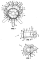
- FIG. 1 provides a perspective view for a preferred embodiment of the Improved Stabilizer.
- FIG. 2 is an exploded view for the embodiment of FIG. 1 .
- FIG. 3 shows the embodiment of FIG. 1 with the cover removed.
- FIG. 4 is a lateral view of a preferred embodiment of the wiper.
- FIG. 5 is a cutaway view of the preferred embodiment of the wiper taken along line 5-5 in FIG. 4 looking in the direction of the arrows.
- FIG. 6 is a lateral view of a preferred embodiment of the control shaft, which has been inserted into the preferred embodiment of the wiper of FIG. 4 .
- FIG. 7 is a lateral view of the preferred embodiment of the control shaft from FIG. 6 without the control shaft being inserted into the wiper.
- FIG. 8 is a cutaway view of the preferred embodiment of the control shaft from FIG. 6 and the preferred embodiment of the wiper from FIG. 4 taken along the line 8-8 in FIG. 6 looking in the direction of the arrows.
- FIG. 9 is a cutaway view of the preferred embodiment of the control shaft from FIG. 6 and the preferred embodiment of the wiper from FIG. 4 taken along the line 9-9 in FIG. 7 looking in the direction of the arrows.
- the preferred embodiment of the Improved Stabilizer of the present invention comprises-as shown in FIG. 1 , in FIG. 2 (in exploded form), and in FIG. 3-a housing 1 having a generally sector-shaped chamber 2 with a first side wall 3, a second side wall 4, a peripheral wall 5, a bottom 6, and a rotatably mounted wiper 7.
- faceplate 8 is sealingly mounted to the housing 1 to constitute the top of the housing 1, although the top of the housing 1 could be integral with the housing 1 so long as the wiper 7 can be introduced into the housing 1 with any means known in the art.
- the wiper 7 has dimensions such that it sealingly moves past the faceplate 8, the housing 1 at the bottom 6 of the chamber 2, and the peripheral wall 5 of the housing 1.
- the wiper 7 comprises, as seen in FIGS. 2 , 3, 4, 5 , 6, and 8 , a rotor 9 and a paddle 10 extending outward from the rotor 9. Furthermore, the rotor 9 has, as depicted in FIGS. 4 and 5 , a cylindrically shaped hollow interior 11 running from the top 12 to the bottom 13 of the rotor 9.
- a first segment 18 of a channel (or circuit) 19 provides fluid communication between (a) the first side 20 of the chamber 2 of the housing 1 within which the wiper 7 is located, the wiper 7 dividing, as shown in FIG. 3 , the chamber 2 into the first side 20 and a second side 21, and (b) the interior 11 of the rotor 9.
- a second segment 22 of the channel (or circuit) 19 provides fluid communication between (c) the second side 21 of the chamber 2 and (d) the interior 11 of the rotor 9.
- the control shaft 14 is so aligned with the first segment 18 and the second segment 22 of the channel (or circuit) 19 that the first segment 18, the second segment 22, and the continuous indentation 23 form the complete channel (or circuit) 19, as can be seen in FIGS. 6 and 8 .
- the control shaft 14, therefore, completely blocks the bypass channel (or circuit) 19 when the first area 24 has been rotated into the bypass channel (or circuit) 19; preferably leaves the bypass channel (or circuit) 19 substantially completely open when the area 25 immediately preceding the area 24 where the continuous indentation 23 ends, i.e., the area 25 with the largest cross section (preferably, as a result of being the area with the deepest point of the indentation 23) has been rotated into the bypass channel (or circuit) 19; and continuously varies the percentage of opening of the bypass channel (or circuit) 19 when areas between area 24 and area 25 are rotated into the bypass channel (or circuit) 19. Dampening is of course maximized when the bypass channel (or circuit) 19 is completely closed and minimized when the bypass channel (or circuit) 19 is completely opened.
- the stabilizer provided damping equivalent to that of a traditional stabilizer.
- the present inventor believes that only one of the segments 18, 22 need be nonlinear and that the degree of nonlinearity can be less than a bend of substantially ninety degrees, having both the first and second segments 18, 22 contain a bend of substantially ninety degrees is, the inventor's most preferred embodiment.
- the top 26 of the knob 15 preferably bevels upward near the outer circular edge 27 of the knob 15.
- a scalloped outer edge 28 actually exists outward from the outer circular edge 27 in order to facilitate gripping the knob 15 but is immaterial to the beveling and its function, and references herein to outer edge are not intended to exclude a more outer or outermost edge e.g. adapted for gripping (or for a tool).
- This causes the outer circular edge 27 to be higher than the central portion 29.
- the beveling could be done in reverse, i.e., the central portion 29 could be higher than the outer circular edge 27. This may be associated with a higher angle of beveling, perhaps greater than 45 degrees.
- Indicators 30, such as numbers, designate the position of the knob 15 and, consequently, the rotational position of the control shaft 14 and, consequently, the continuous indentation 23 so that a rider will know the resultant degree of damping which has been selected.
- These numbers are placed on the beveled portion 31 of the top 26 of the knob 15, and the amount of beveling is selected such that only one such indicator 30 will be clearly visible to a rider of a motorcycle when the rider has the rider's head in the traditional motorcycle racing position.
- the degree of beveling will depend on the particular application but a suitable range is readily apparent to one skilled in the art; it will almost always be greater than 5 and normally at least 10 degrees, often about 20 to 50 degrees, perhaps about 30 to 45 degrees, rarely much more than about 60 degrees for a concave bevel.
- the precise angle is not critical and can be readily selected to give appropriate visibility for a range of expected riders and possibly also for a range of applications.
- a first cavity 38 runs, as depicted in FIGS. 4 through 6 , on the first side 17 of the paddle 10 from near the free end 39 of the paddle 10 to the first segment 18 of the bypass channel (or circuit) 19 that provides fluid communication between (a) the first side 20 of the chamber 2 of the housing 1 within which the wiper 7 is located and (b) the interior 11 of the rotor 9. This facilitates the flow of fluid into the first segment 18 of the bypass channel (or circuit) 19 when the first side 17 of the paddle 10 nears the first side wall 3 of the chamber 2.
- a second cavity 40 runs on the second side 41 of the paddle 10 from near the free end 39 of the paddle 10 to the second segment 22 of the bypass channel (or circuit) 19 that provides fluid communication between (a) the second side 21 of the chamber 2 of the housing 1 within which the wiper 7 is located and (b) the interior 11 of the rotor 9. This facilitates the flow of fluid into the second segment 22 of the bypass channel (or circuit) 19 when the first side 17 of the paddle 10 nears the second side wall 4 of the chamber 2.
- a number of seals of the type known in the art are employed. Such a seal is placed in the upper groove 42 of the housing 1 near the periphery 43 of the chamber 2; in the groove 44 within the inner edge 45 of the bottom 6 of the chamber 2 surrounding an aperture 46 into which the lower portion 47 of the rotor 9 fits, such seal preferably being a traditional o-ring; in the groove 48 within the inner edge 49 of the faceplate 8 surrounding an aperture 50 into which the upper portion 51 of the rotor 9 fits, such seal preferably being a traditional o-ring; in the groove 52 near the top 16 of the control shaft 14, such seal preferably being a traditional o-ring; in the groove 53 above and near the continuous indentation 23, such seal preferably being a traditional o-ring; and in the groove 54 below and near the continuous indentation 23.
- a groove 55 for a keeper ring is located near the bottom 56 of the control shaft 14. Just above and also below the groove 55 for the keeper ring the control shaft 14 is, as illustrated in FIGS. 4 and 6 , narrower than it is above, creating a shelf 57 which is removably located above an inward projection 58 from the interior wall 59 of the rotor 9 which surrounds the hollow interior 11 of the rotor 9. Consequently, since the knob 15 is preferably wider than the hollow interior 11 of the rotor 9, both the knob 15, in conjunction with the rotor 9, itself, and the inward projection in conjunction with the shelf 57 preclude the control shaft 14 from falling out the bottom 13 of the rotor 9. Similarly, having in the groove 55 any keeper ring that is well known in the art precludes the control shaft 14 from being removed from the top 12 of the rotor 9.
- the vertically middle portion 60 of the exterior side 61 of the rotor 9 extends, as portrayed in FIG. 4 , outward a sufficient distance that it is past the inner edge 45 of the bottom 6 of the chamber 2 and also past the inner edge 49 of the faceplate 8 in order to enhance the effect of the paddle 10 in precluding the rotor 9 from passing through either (a) the aperture 46 in the bottom 6 of the chamber 2 into which the lower portion 47 of the rotor 9 fits or (b) the aperture 50 in the faceplate into which the upper portion 51 of the rotor 9 fits.
- screws 62 are, as illustrated in FIG. 2 , utilized to attach the faceplate 8 to threaded channels 63 in the housing 1 and also to connect the arm 64 to threaded channels 65 in the bottom 13 of the rotor 9. Similarly, as shown in FIGS.
- a threaded plug 66 is preferably utilized both (a) to close the threaded aperture 67 in the rotor that is created by the preferred method, i.e ., drilling, of making the innermost portion 68 of the first segment 18 of the bypass channel (or circuit) 19 and the innermost portion 69 of the second segment 22 of the bypass channel (or circuit) 19 and (b) to close the apertures 70, 71 in the bottom 6 of the chamber 2 that serve as an alternate to removing the faceplate 8 for filling the chamber 2 with fluid.
- chamber 2 there can, however, be more than one chamber 2 provided that a paddle 10 is attached to the rotor 9 in each chamber 2, as described above for a single chamber 2.
- chamber 2 there must also be a first segment 18 and a second segment 22 of a bypass channel (or circuit) 19 for each chamber 2, although the portion 72 of the bypass channel (or circuit) 19 which is adjacent to the continuous indentation 23 in the control shaft 14 may be common (communicating with the segments 18, 22 for all chambers 2). It is, though, preferable to have a vertically separated portion 72 for each chamber 2.
- Any fluid that is known in the art for use in steering stabilizers may be utilized in the present invention. This includes, but is not necessarily limited to, motor oil and transmission fluid.
- the term “substantially” indicates that one skilled in the art would consider the value modified by such terms to be within acceptable limits for the stated value. Also as used herein the term “preferable” or “preferably” means that a specified element or technique is more acceptable than another but not that such specified element or technique is a necessity.
Landscapes
- Engineering & Computer Science (AREA)
- General Engineering & Computer Science (AREA)
- Mechanical Engineering (AREA)
- Vehicle Body Suspensions (AREA)
- Fluid-Damping Devices (AREA)
- Multiple-Way Valves (AREA)
Applications Claiming Priority (1)
| Application Number | Priority Date | Filing Date | Title |
|---|---|---|---|
| US11/811,937 US7789207B2 (en) | 2002-06-10 | 2007-06-11 | Stabilizer |
Publications (2)
| Publication Number | Publication Date |
|---|---|
| EP2003365A2 true EP2003365A2 (fr) | 2008-12-17 |
| EP2003365A3 EP2003365A3 (fr) | 2015-05-06 |
Family
ID=39970967
Family Applications (1)
| Application Number | Title | Priority Date | Filing Date |
|---|---|---|---|
| EP20080158070 Withdrawn EP2003365A3 (fr) | 2007-06-11 | 2008-06-11 | Stabilisateur amélioré |
Country Status (3)
| Country | Link |
|---|---|
| US (1) | US7789207B2 (fr) |
| EP (1) | EP2003365A3 (fr) |
| AU (1) | AU2008202530B2 (fr) |
Families Citing this family (7)
| Publication number | Priority date | Publication date | Assignee | Title |
|---|---|---|---|---|
| US7631735B1 (en) * | 2006-05-03 | 2009-12-15 | Vanvalkenburgh Charlie N | Mounting system for rotary damper |
| US8540062B2 (en) * | 2011-05-20 | 2013-09-24 | Research In Motion Limited | Low profile rotary damper |
| JP6817118B2 (ja) * | 2017-03-15 | 2021-01-20 | オイレス工業株式会社 | ロータリダンパ |
| US10946925B2 (en) * | 2017-12-14 | 2021-03-16 | George John Athanasiou | Multi positional rotary steering damper assembly |
| KR102274619B1 (ko) * | 2019-07-11 | 2021-07-06 | 박종관 | 돌발상황 발생시 핸들의 임의 꺾임을 방지하는 킥보드용 댐퍼 |
| CA3159124A1 (fr) * | 2021-05-20 | 2022-11-20 | 9257-5810 Quebec Inc. | Amortisseur pour un godet de travail du sol |
| CA3198126A1 (fr) * | 2022-10-31 | 2024-04-30 | Bombardier Recreational Products Inc. | Embarcation personnelle comprenant un amortisseur de direction |
Citations (8)
| Publication number | Priority date | Publication date | Assignee | Title |
|---|---|---|---|---|
| US4773514A (en) | 1984-11-28 | 1988-09-27 | Per Hakan Albertsson | Hydraulic damping device |
| US6401884B2 (en) | 1999-12-28 | 2002-06-11 | Ralph S. Norman | Fluidic dampening device |
| US20030136621A1 (en) | 1999-12-28 | 2003-07-24 | Norman Ralph S. | Fluidic dampening device |
| GB2389637A (en) | 2002-06-10 | 2003-12-17 | Ralph Stuart Norman | A fluidic rotary damping device which includes a rotatably mounted wiper disposed in a fluid-filled chamber |
| US6802519B2 (en) | 2002-09-09 | 2004-10-12 | Rtt Motorsports, Llc | Steering damper |
| US6899208B2 (en) | 2001-12-17 | 2005-05-31 | Charles N. VanValkenburgh | Rotary damper |
| US20050199456A1 (en) | 2004-03-15 | 2005-09-15 | Norman Ralph S. | Fluidic dampening device |
| US20060006029A1 (en) | 2002-06-10 | 2006-01-12 | Norman Ralph S | Fluidic stabilizer with remote control |
Family Cites Families (12)
| Publication number | Priority date | Publication date | Assignee | Title |
|---|---|---|---|---|
| US1506495A (en) * | 1921-09-27 | 1924-08-26 | Macrae Thomas | Shock absorber |
| FR556145A (fr) * | 1922-09-27 | 1923-07-12 | ||
| BE343586A (fr) * | 1926-08-03 | |||
| US2038587A (en) * | 1928-07-11 | 1936-04-28 | Houde Eng Corp | Hydraulic shock absorber |
| DE589881C (de) * | 1930-10-14 | 1933-12-16 | Ludwig Ferdinand Steinmetz | Fluessigkeitsstossdaempfer, insbesondere fuer Kraftfahrzeuge |
| US5159997A (en) * | 1990-10-31 | 1992-11-03 | Enertrols, Inc. | Miniature shock absorber |
| US5988329A (en) * | 1997-11-20 | 1999-11-23 | Turn-Act, Inc. | Rotary damper |
| JP4493066B2 (ja) * | 2001-04-06 | 2010-06-30 | 本田技研工業株式会社 | 自動2輪車用ステアリングダンパ装置 |
| JP4571338B2 (ja) * | 2001-05-25 | 2010-10-27 | 本田技研工業株式会社 | 車両用ステアリングダンパー装置 |
| JP4197592B2 (ja) * | 2001-12-28 | 2008-12-17 | 本田技研工業株式会社 | ステアリングダンパ装置 |
| US7021433B2 (en) * | 2003-03-20 | 2006-04-04 | Honda Motor Co., Ltd. | Vehicle steering damper, steering damper kit for motorcycle, and motorcycle incorporating same |
| JP4493074B2 (ja) * | 2004-02-05 | 2010-06-30 | 本田技研工業株式会社 | 自動2輪車のステアリングダンパ装置 |
-
2007
- 2007-06-11 US US11/811,937 patent/US7789207B2/en not_active Expired - Fee Related
-
2008
- 2008-06-06 AU AU2008202530A patent/AU2008202530B2/en not_active Ceased
- 2008-06-11 EP EP20080158070 patent/EP2003365A3/fr not_active Withdrawn
Patent Citations (8)
| Publication number | Priority date | Publication date | Assignee | Title |
|---|---|---|---|---|
| US4773514A (en) | 1984-11-28 | 1988-09-27 | Per Hakan Albertsson | Hydraulic damping device |
| US6401884B2 (en) | 1999-12-28 | 2002-06-11 | Ralph S. Norman | Fluidic dampening device |
| US20030136621A1 (en) | 1999-12-28 | 2003-07-24 | Norman Ralph S. | Fluidic dampening device |
| US6899208B2 (en) | 2001-12-17 | 2005-05-31 | Charles N. VanValkenburgh | Rotary damper |
| GB2389637A (en) | 2002-06-10 | 2003-12-17 | Ralph Stuart Norman | A fluidic rotary damping device which includes a rotatably mounted wiper disposed in a fluid-filled chamber |
| US20060006029A1 (en) | 2002-06-10 | 2006-01-12 | Norman Ralph S | Fluidic stabilizer with remote control |
| US6802519B2 (en) | 2002-09-09 | 2004-10-12 | Rtt Motorsports, Llc | Steering damper |
| US20050199456A1 (en) | 2004-03-15 | 2005-09-15 | Norman Ralph S. | Fluidic dampening device |
Also Published As
| Publication number | Publication date |
|---|---|
| EP2003365A3 (fr) | 2015-05-06 |
| US7789207B2 (en) | 2010-09-07 |
| AU2008202530A1 (en) | 2009-01-08 |
| AU2008202530B2 (en) | 2011-10-27 |
| US20080105506A1 (en) | 2008-05-08 |
Similar Documents
| Publication | Publication Date | Title |
|---|---|---|
| EP2003365A2 (fr) | Stabilisateur amélioré | |
| JP2593461B2 (ja) | 自動二輪車の後輪用油圧式減衰装置 | |
| JP4909763B2 (ja) | ステアリングダンパ | |
| US6401884B2 (en) | Fluidic dampening device | |
| US20090260936A1 (en) | Fluidic Stabilizer with Remote Control | |
| EP1323946B1 (fr) | Amortisseur pour guidon | |
| JP4555750B2 (ja) | ステアリングダンパ装置 | |
| US7231867B2 (en) | Rotary damper | |
| JPS63240469A (ja) | 動力舵取装置用サ−ボ弁装置 | |
| SE509921C2 (sv) | Styrservo till drivaggregat för båtar | |
| US8408572B2 (en) | Steering damper with active adjustment of damping characteristics | |
| US20130306418A1 (en) | Fluidic Dampening Device | |
| JP2005343338A (ja) | ステアリングダンパ装置 | |
| JP4229377B2 (ja) | 緩衝器 | |
| JP2008143355A (ja) | ステアリングダンパ | |
| JP2002331997A (ja) | 船外機用操舵装置 | |
| US20060225978A1 (en) | Adjustable shock absorbing device for a front fork of a bicycle | |
| JPH0971283A (ja) | フロントフォークの衝撃減衰調整機構 | |
| JP4157638B2 (ja) | 二輪車用ステアリング構造 | |
| EP2496468B1 (fr) | Amortisseur de direction à réglage actif des caractéristiques d'amortissement | |
| KR100532724B1 (ko) | 차량용 파워 스티어링 장치의 밸브 어셈블리 장치 | |
| JPS6221167Y2 (fr) | ||
| JP2005112294A (ja) | ステアリングダンパ装置 | |
| JP2004239440A (ja) | 減衰装置 | |
| JPS6330621A (ja) | 車両用油圧緩衝器 |
Legal Events
| Date | Code | Title | Description |
|---|---|---|---|
| PUAI | Public reference made under article 153(3) epc to a published international application that has entered the european phase |
Free format text: ORIGINAL CODE: 0009012 |
|
| AK | Designated contracting states |
Kind code of ref document: A2 Designated state(s): AT BE BG CH CY CZ DE DK EE ES FI FR GB GR HR HU IE IS IT LI LT LU LV MC MT NL NO PL PT RO SE SI SK TR |
|
| AX | Request for extension of the european patent |
Extension state: AL BA MK RS |
|
| PUAL | Search report despatched |
Free format text: ORIGINAL CODE: 0009013 |
|
| AK | Designated contracting states |
Kind code of ref document: A3 Designated state(s): AT BE BG CH CY CZ DE DK EE ES FI FR GB GR HR HU IE IS IT LI LT LU LV MC MT NL NO PL PT RO SE SI SK TR |
|
| AX | Request for extension of the european patent |
Extension state: AL BA MK RS |
|
| RIC1 | Information provided on ipc code assigned before grant |
Ipc: F16F 9/14 20060101AFI20150331BHEP Ipc: B62K 21/08 20060101ALI20150331BHEP |
|
| 17P | Request for examination filed |
Effective date: 20151106 |
|
| RBV | Designated contracting states (corrected) |
Designated state(s): AT BE BG CH CY CZ DE DK EE ES FI FR GB GR HR HU IE IS IT LI LT LU LV MC MT NL NO PL PT RO SE SI SK TR |
|
| AKX | Designation fees paid |
Designated state(s): AT BE BG CH CY LI |
|
| AXX | Extension fees paid |
Extension state: MK Extension state: BA Extension state: RS Extension state: AL |
|
| REG | Reference to a national code |
Ref country code: DE Ref legal event code: R108 |
|
| RBV | Designated contracting states (corrected) |
Designated state(s): AT BE BG CH CY CZ LI |
|
| RBV | Designated contracting states (corrected) |
Designated state(s): AT BE BG CH CY CZ DE DK EE ES FI FR GB GR HR HU IE IS IT LI LT LU LV MC MT NL NO PL PT RO SE SI SK TR |
|
| STAA | Information on the status of an ep patent application or granted ep patent |
Free format text: STATUS: THE APPLICATION IS DEEMED TO BE WITHDRAWN |
|
| 18D | Application deemed to be withdrawn |
Effective date: 20190103 |