EP2003381A2 - Ventil in einer Vorrichtung für die Kryotherapie - Google Patents
Ventil in einer Vorrichtung für die Kryotherapie Download PDFInfo
- Publication number
- EP2003381A2 EP2003381A2 EP08010085A EP08010085A EP2003381A2 EP 2003381 A2 EP2003381 A2 EP 2003381A2 EP 08010085 A EP08010085 A EP 08010085A EP 08010085 A EP08010085 A EP 08010085A EP 2003381 A2 EP2003381 A2 EP 2003381A2
- Authority
- EP
- European Patent Office
- Prior art keywords
- valve
- valve according
- valve needle
- carbon dioxide
- electromagnet
- Prior art date
- Legal status (The legal status is an assumption and is not a legal conclusion. Google has not performed a legal analysis and makes no representation as to the accuracy of the status listed.)
- Granted
Links
Images

Classifications
-
- F—MECHANICAL ENGINEERING; LIGHTING; HEATING; WEAPONS; BLASTING
- F16—ENGINEERING ELEMENTS AND UNITS; GENERAL MEASURES FOR PRODUCING AND MAINTAINING EFFECTIVE FUNCTIONING OF MACHINES OR INSTALLATIONS; THERMAL INSULATION IN GENERAL
- F16K—VALVES; TAPS; COCKS; ACTUATING-FLOATS; DEVICES FOR VENTING OR AERATING
- F16K31/00—Actuating devices; Operating means; Releasing devices
- F16K31/02—Actuating devices; Operating means; Releasing devices electric; magnetic
- F16K31/06—Actuating devices; Operating means; Releasing devices electric; magnetic using a magnet, e.g. diaphragm valves, cutting off by means of a liquid
- F16K31/08—Actuating devices; Operating means; Releasing devices electric; magnetic using a magnet, e.g. diaphragm valves, cutting off by means of a liquid using a permanent magnet
- F16K31/082—Actuating devices; Operating means; Releasing devices electric; magnetic using a magnet, e.g. diaphragm valves, cutting off by means of a liquid using a permanent magnet using a electromagnet and a permanent magnet
Definitions
- the invention relates to a valve for use in a device for cryotherapy, with a loaded with liquefied carbon dioxide pressure side and with an outlet opening connected to the discharge side, in which a valve needle by means of an electromagnet, which has a slider from a seal seat for opening the valve is liftable.
- Cryotherapy is the treatment of various conditions caused by the superficial action of extreme cold. This is known to result in various physiological effects, e.g. the lowering of the pain threshold, a reduction of spasticity, a relaxation of muscle fibers or even a hemostatic effect.
- the EP-0 633 008 instead of using nitrogen liquefied carbon dioxide, which is taken from a pressure bottle and passed through a pressure-resistant line to a gun-like device in which it is relaxed and then ejected.
- the ejected gas can reach temperatures of minus 75 ° C, allowing the treated skin to be cooled down from its normal temperature (about 32 ° C) within a few seconds to temperatures of 0 ° C to 5 ° C.
- Corresponding devices for this purpose are known, for example, from the documents EP 1 059 904 or EP 1 328 205 ,
- thermal shock e.g. leads to a neuroreflector dilation of the vessels in the affected area, whereby inflammatory mediators are transported away faster.
- a mechanical actuation is provided for the valve provided therewith, with which the outflow of CO 2 is controlled.
- This is relatively unwieldy.
- it is relatively tiring to manually apply a permanent force, with which the valve is kept open against the force of a spring.
- the pressures to be controlled by the valve can be 50-60 bar and higher on the pressure side.
- Object of the present invention is in this aspect to improve a device of the type described above in terms of their energy consumption in the operation of the valves.
- the slider which is moved over the electromagnet and via which a valve needle is lifted by a seal seat for opening the valve, is designed to be permanently magnetic on a lying outside the coil of the electromagnet end.
- this is achieved, in particular, in that at least one disk magnet is attached to the end as a permanent magnet.
- Such disc magnets are commercially available and thus offer a possibility to realize the desired permanent magnetic configuration at the one slider end in a simple manner.
- the corresponding permanent magnet equipped end is disposed within a ferromagnetic annular disc, which is placed in particular in the axial extension of the coil, the desired effect can be realized.
- This annular disc is provided in particular outside of a ring core directly adjacent to a leg of a belonging to the toroidal clamp.
- the carbon dioxide relaxing along the valve needle by the electromagnet lead and for this purpose at least one side of the valve needle to provide a parallel to its axis extending flow channel.
- the valve needle for this purpose has a substantially circular cross section with at least one laterally flattened portion. If such a valve needle is guided in a known manner in a circular bore, the laterally flattened portion acts as a corresponding passage, in which due to its free cross section, the flow rate of the flowing CO 2 is adjusted so that the unwanted dry ice does not form.
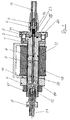
- a tubular sleeve 1 has at its one end shown here on the right hand side a flange and at the other end it is provided with a bottom, with an external thread and with an axial connection bore through the bottom.
- a slider 3 In the interior of this sleeve 1, a slider 3 is inserted, which is provided with an axial bore. In this axial bore, a valve needle 4 is inserted and fixed with a screw 22 in the axial direction. The slider 3 comes to lie in front of the bottom of the sleeve 1 and is movable in its axial direction. In the open end of the sleeve 1, a plug 2 is then inserted in front of the slide 3, which also has an axial bore which is aligned with the axial bore of the slider 3. The valve needle 4 runs through this axial bore of the plug 2, which is sealed in the axial bore of the sleeve 1 via an O-ring seal 13.
- the plug 2 is provided at its lying outside the sleeve 1 end with a flange which is adjacent to the flange of the sleeve 1 and on which with screws 20 with the interposition of an O-ring 15 as a gasket a connector 5 is attached.
- a connecting hose 16 is attached to a union nut 6 with the interposition of a clamping ring 7, which leads to a (not shown) filled with liquid carbon dioxide pressure bottle and having an internal pressure of about 50 - 60 bar.
- This tube 16 is connected by the axial bore in the projection of the connecting piece 5 with a provided in this chamber in flow communication, where a spring 14 in the axial direction presses on a head 23 of the valve needle 4 and presses against a seal 11.
- a clamp 10 for a toroidal core which surrounds the coil 18 of the electromagnet U-shaped, which is coaxial with the sleeve 1 also placed on this in the attack.
- the slide 3 is provided at its left end with a disc magnet 17 which is arranged axially in the region outside of the sleeve 1 through the ferromagnetic disc 9 is covered.
- valve needle 4 has flattened side surfaces 12, so that when used in a circular bore, for example, in the plug 2, parallel to their longitudinal extent extending cavities 19, the flow channels form, in which the flowing CO 2 of it is prevented to form undesirable dry ice.
Landscapes
- Engineering & Computer Science (AREA)
- General Engineering & Computer Science (AREA)
- Physics & Mathematics (AREA)
- Electromagnetism (AREA)
- Mechanical Engineering (AREA)
- Magnetically Actuated Valves (AREA)
Abstract
Description
- Die Erfindung betrifft ein Ventil zur Verwendung in einer Vorrichtung für die Kryotherapie, mit einer mit verflüssigtem Kohlendioxid beaufschlagten Druckseite und mit einer mit einer Auslassöffnung verbundenen Abgabeseite, in welchem eine Ventilnadel mittels eines Elektromagneten, der einen Schieber aufweist, von einem Dichtungssitz zum Öffnen des Ventils anhebbar ist.
- Unter der Kryotherapie versteht man die Behandlung von verschiedenen Leiden durch oberflächliche Einwirkung großer Kälte. Diese führt bekanntermaßen zu verschiedenen physiologischen Wirkungen, z.B. der Herabsetzung der Schmerzschwelle, einer Verminderung der Spastik, eine Entspannung von Muskelfasern oder auch einer blutstillenden Wirkung.
- Früher wurde hierzu insbesondere verflüssigter Stickstoff benutzt, der allerdings aufgrund der speziellen Bedingungen, unter denen er gelagert werden muss, schwere unhandliche Vorrichtungen benötigt. Aus diesen Vorrichtungen verdampfte der verflüssigte Stickstoff ständig, was unerwünschte Verluste verursachte. Außerdem ist flüssiger Stickstoff nur mit hohem Aufwand zu transportieren und großflächig bereitzustellen, was seinem Einsatz entsprechend entgegensteht.
- Es ist diesbezüglich beispielsweise aus der
EP-0 633 008 bekannt, statt Stickstoff verflüssigtes Kohlendioxid zu verwenden, das aus einer Druckflasche entnommen wird und über eine druckfeste Leitung zu einer pistolenartigen Vorrichtung geführt wird, in der es entspannt und dann ausgestoßen wird. Dabei kann das ausgestoßene Gas Temperaturen von minus 75 °C erreichen, wodurch die hiermit behandelte Haut innerhalb weniger Sekunden von ihrer Normaltemperatur (ca. 32 °C) heruntergekühlt werden kann auf Temperaturen von 0 °C bis 5 °C. - Entsprechende Vorrichtungen hierzu, insbesondere auch für einen mobilen Einsatz, sind beispielsweise bekannt aus den Druckschriften
EP 1 059 904 oderEP 1 328 205 . - Es hat sich dabei herausgestellt, dass der entsprechende Thermoschock, z.B. zu einer neuroreflektorischen Ausdehnung der Gefäße im betroffenen Bereich führt, wodurch Entzündungsmediatoren schneller abtransportiert werden.
- Weitere Wirkungsweisen sind noch nicht abschließend wissenschaftlich erforscht.
- Bei der Vorrichtung, die in der oben erstgenannten Druckschrift beschrieben wird, wird für das dort vorgesehene Ventil, mit dem das Ausströmen von CO2 gesteuert wird, eine mechanische Betätigung vorgesehen. Diese ist relativ unhandlich. Außerdem ist es relativ anstrengend, auf Dauer manuell eine Kraft aufzubringen, mit der das Ventil gegen die Kraft einer Feder geöffnet gehalten wird. Dabei ist auch zu berücksichtigen, dass die mit dem Ventil zu beherrschenden Drücke druckseitig bei 50 - 60 bar und höher liegen können.
- Bei den nachgenannten Vorrichtungen für den mobilen Einsatz in der Kryotherapie werden statt eines mechanischen Ventiles elektrisch betätigte Magnetventile eingesetzt. Es hat sich dabei aber herausgestellt, dass diese für ihre Betätigung erheblich Erregerströme benötigen, so dass die für die Betätigung der Elektromagneten vorgesehene Batterien, Akkumulatoren o.ä. relativ schnell "verbrauchen", was generell als nachteilig empfunden wird.
- Aufgabe der vorliegenden Erfindung ist es unter diesem Aspekt, eine Vorrichtung der eingangs beschriebenen Art im Hinblick auf ihren Energieverbrauch bei der Betätigung der Ventile zu verbessern.
- Diese Aufgabe wird erfindungsgemäß dadurch gelöst, dass der Schieber, der über den Elektromagneten bewegt wird und über den eine Ventilnadel von einem Dichtungssitz zum Öffnen des Ventils angehoben wird, an einem außerhalb der Spule des Elektromagneten liegenden Ende dauermagnetisch ausgestaltet ist.
- Bei einer besonders bevorzugten Ausführungsform wird dies insbesondere dadurch erreicht, dass an dem besagten Ende als Permanentmagnet wenigstens ein Scheibenmagnet befestigt ist. Solche Scheibenmagnete sind käuflich erwerblich und bieten damit eine Möglichkeit, die erwünschte dauermagnetische Ausgestaltung an dem einen Schieberende auf einfache Weise zu realisieren.
- Insbesondere, indem das entsprechend dauermagnetisch ausgestattete Ende innerhalb einer ferromagnetischen Ringscheibe angeordnet ist, die insbesondere in axialer Verlängerung der Spule platziert ist, lässt sich der gewünschte Effekt realisieren.
- Diese Ringscheibe ist dabei insbesondere außerhalb eines Ringkernes vorgesehen direkt neben einem Schenkel einer zu dem Ringkern gehörenden Klammer.
- Eine derartige Konstruktion hat überraschenderweise zu einer erheblichen Absenkung der für die Betätigung des Magnetventils benötigten Betriebsspannung geführt bei einem gleichzeitig erhöhten Magnetfluss. Hierdurch kann die für eine Magnetbetätigung benötigte Energie effizienter eingesetzt werden. Entsprechende Geräte für die Kryotherapie können somit insgesamt kleiner und leichter ausgestaltet werden, da ein entsprechend vorzusehendes Elektromagnetventil kleiner ausgestaltet sein kann und/oder eine vorzusehende Energieversorgung (sei es ein Akku, eine Batterie oder ein Transformator) kleiner auszulegen und damit preiswerter zu realisieren ist.
- Um eine Durchströmung des Ventils zu gewährleisten, ohne dass sich in diesem in unerwünschter Weise Trockeneis o.ä. bildet, wird vorgeschlagen, das zu entspannende Kohlendioxid entlang der Ventilnadel durch den Elektromagnet zu führen und hierfür an der Ventilnadel wenigstens einseitig einen parallel zu ihrer Achse verlaufenden Durchströmkanal vorzusehen.
- Bei einer fertigungstechnisch bevorzugten Variante weist die Ventilnadel hierzu einen im wesentlichen kreisförmigen Querschnitt auf mit wenigstens einem seitlich abgeflachten Abschnitt. Wenn eine solche Ventilnadel in bekannter Weise in einer kreisrunden Bohrung geführt wird, fungiert der seitlich abgeflachte Abschnitt als entsprechender Durchtrittskanal, bei dem aufgrund seines freien Querschnittes die Strömungsgeschwindigkeit des durchströmenden CO2 so einzustellen ist, dass sich das unerwünschte Trockeneis nicht bildet.
- Weitere Vorteile und Merkmale der Erfindung ergeben sich aus der nachfolgenden Beschreibung eines Ausführungsbeispiels. Dabei zeigt:
- Figur 1
- die geschnittene Seitenansicht eines erfindungsgemäßen Magnetventils,
- Figur 2
- die Schnittansicht einer eingebauten Ventilnadel.
- In der
Figur 1 erkennt man den Längsschnitt durch ein erfindungsgemäßes Ventil. Eine rohrförmige Hülse 1 weist an ihrem hier rechts dargestellten einen Ende einen Flansch auf und an dem anderen Ende ist sie mit einem Boden, mit einem Außengewinde und mit einer axialen Anschlussbohrung durch den Boden hindurch versehen. - In das Innere dieser Hülse 1 wird ein Schieber 3 eingeführt, der mit einer axialen Bohrung versehen ist. In dieser axialen Bohrung ist eine Ventilnadel 4 eingesetzt und mit einer Schraube 22 in Axialrichtung fixiert. Der Schieber 3 kommt vor dem Boden der Hülse 1 zu liegen und ist in deren Axialrichtung beweglich. In das offene Ende der Hülse 1 wird dann vor dem Schieber 3 ein Stopfen 2 eingesetzt, der ebenfalls eine axiale Bohrung aufweist, die mit der axialen Bohrung des Schiebers 3 fluchtet. Die Ventilnadel 4 läuft dabei durch diese axiale Bohrung des Stopfens 2, der in der axialen Bohrung der Hülse 1 über eine O-Ringdichtung 13 abgedichtet ist.
- Der Stopfen 2 ist an seinem außerhalb der Hülse 1 liegenden Ende mit einem Flansch versehen, der neben dem Flansch der Hülse 1 liegt und an dem mit Schrauben 20 unter Zwischenlage eines O-Ringes 15 als Dichtung ein Anschlussstück 5 befestigt ist. Auf einem durchbohrten Vorsprung dieses Anschlussstückes 5 ist mit einer Überwurfmutter 6 unter Zwischenschaltung eines Klemmringes 7 ein Anschlussschlauch 16 befestigt, der zu einer (nicht dargestellten) mit flüssigem Kohlendioxid gefüllten Druckflasche führt und einen Innendruck von etwa 50 - 60 bar aufweist. Dieser Schlauch 16 steht durch die axiale Bohrung im Vorsprung des Anschlussstückes 5 mit einer in diesem vorgesehenen Kammer in Strömungsverbindung, wo eine Feder 14 in Axialrichtung auf einen Kopf 23 der Ventilnadel 4 drückt und diese gegen eine Dichtung 11 presst.
- Auf das Äußere der Hülse 1 ist im Anschlag gegen deren Flansch von links eine Klammer 10 für einen Ringkern gesetzt, die die Spule 18 des Elektromagneten U-förmig umgreift, die koaxial zu der Hülse 1 ebenfalls auf dieser aufgesetzt ist.
- In axialer Verlängerung der Spule 18 sitzt außerhalb der Klammer 10 des Ringkerns benachbart zu deren linkem Schenkel eine ferromagnetische Scheibe 9, die über eine Sechskantmutter 21, die auf dem Außengewinde der Hülse 1 aufgeschraubt wird, gegen die Klammer 10 und mit dieser zusammen mit der Spule 18 von links gegen den Flansch der Hülse 1 gepresst wird. In den Boden der Hülse 1 ist ein Anschlussstutzen 8 eingeschraubt mit dem ein Schlauch 24 gehalten wird, der zu der (ebenfalls nicht dargestellten) Ausgabeöffnung einer Kryotherapievorrichtung führt.
- Das soweit konstruktiv beschriebene Ventil funktioniert nun so, dass der Kopf 23 der Ventilnadel 4 durch die Feder 14 gegen die Dichtung 11 gedrückt wird. Bei einer elektrischen Erregung der Spule 18 wird ein Magnetfeld aufgebaut, das durch den Ringkern mit der Klammer 10 verstärkt wird, wodurch dann auf den Schieber 3 eine Axialkraft ausgeübt wird, die über die Ventilnadel 4 der Kraft der Feder 14 entgegenwirkt. Der Schieber 3 und die Ventilnadel 4 werden dadurch ein kleines Stück nach links bewegt und damit wird der Kopf 23 von der Dichtung 11 abgehoben. Damit kann das unter hohem Druck im Anschlussschlauch 16 stehende Kohlendioxid durch die axialen Bohrungen im Stopfen 2 und dem Schieber 3 hindurchströmen und am hier dargestellten linken Ende der Hülse 1 in den Schlauch 24 geleitet werden.
- Um die Kräfte, die durch die Spule 18 in magnetischer Weise erzeugt werden zu verstärken, ist im hier dargestellten Beispiel der Schieber 3 an seinem linken Ende mit einem Scheibenmagnet 17 versehen, der axial in dem Bereich angeordnet ist, der außerhalb der Hülse 1 durch die ferromagnetische Scheibe 9 abgedeckt wird.
- Diese Konstruktion resultiert darin, dass die ferromagnetische Scheibe 9 in Zusammenhang mit dem Permanentmagneten 17 einen erhöhten Magnetfluss bewirkt. Die Betriebsspannung für die Betätigung der Spule 18 des Elektromagneten ist damit erheblich abzusenken.
- In der
Figur 2 erkennt man noch, dass die Ventilnadel 4 abgeflachte Seitenflächen 12 aufweist, so dass sich, wenn sie in eine kreisrunde Bohrung z.B. im Stopfen 2 eingesetzt wird, parallel zu ihrer Längserstreckung verlaufende Hohlräume 19 ergeben, die Strömungskanäle bilden, in denen das durchströmende CO2 daran gehindert wird, in unerwünschter Weise Trockeneis zu bilden.
Claims (6)
- Ventil insbesondere zur Verwendung in einer Vorrichtung für die Kryotherapie, mit einer mit verflüssigtem Kohlendioxid beaufschlagten Druckseite (16) und mit einer mit einer Auslassöffnung verbundenen Abgabeseite (24), sowie mit einer Ventilnadel (4), die mittels eines Schiebers (3) eines Elektromagneten von einem Dichtungssitz (11) zum Öffnen des Ventils anhebbar ist,
dadurch gekennzeichnet,
dass der Schieber (3) an einem außerhalb der Spule (18) des Elektromagneten liegenden Endes dauermagnetisch ausgestaltet ist. - Ventil gemäß Anspruch 1,
dadurch gekennzeichnet,
dass an dem besagten Ende wenigstens ein Scheibenmagnet (17) befestigt ist. - Ventil gemäß Anspruch 1,
dadurch gekennzeichnet,
dass das Ende innerhalb einer ferromagnetischen Ringscheibe (9) angeordnet ist. - Ventil gemäß Anspruch 3,
dadurch gekennzeichnet,
dass die Ringscheibe (9) außerhalb eines Ringkernes neben einem Schenkel einer zu diesem gehörenden Klammer (10) angeordnet ist. - Ventil gemäß Anspruch 1,
dadurch gekennzeichnet,
dass die Ventilnadel (4) wenigstens einseitig einen parallel zu ihrer Achse verlaufenden Durchströmkanal (19) aufweist. - Ventil gemäß Anspruch 5,
dadurch gekennzeichnet,
dass die Ventilnadel (4) einen im wesentlichen kreisförmigen Querschnitt hat mit wenigstens einem seitlich abgeflachten Abschnitt (12).
Applications Claiming Priority (1)
| Application Number | Priority Date | Filing Date | Title |
|---|---|---|---|
| DE200710027786 DE102007027786A1 (de) | 2007-06-16 | 2007-06-16 | Ventil in einer Vorrichtung für die Kryotherapie |
Publications (3)
| Publication Number | Publication Date |
|---|---|
| EP2003381A2 true EP2003381A2 (de) | 2008-12-17 |
| EP2003381A3 EP2003381A3 (de) | 2011-03-09 |
| EP2003381B1 EP2003381B1 (de) | 2013-04-24 |
Family
ID=39766869
Family Applications (1)
| Application Number | Title | Priority Date | Filing Date |
|---|---|---|---|
| EP20080010085 Active EP2003381B1 (de) | 2007-06-16 | 2008-06-03 | Ventil in einer Vorrichtung für die Kryotherapie |
Country Status (2)
| Country | Link |
|---|---|
| EP (1) | EP2003381B1 (de) |
| DE (1) | DE102007027786A1 (de) |
Families Citing this family (2)
| Publication number | Priority date | Publication date | Assignee | Title |
|---|---|---|---|---|
| DE102012105347A1 (de) * | 2012-06-20 | 2013-12-24 | Krones Ag | Elektromagnetisches Ventil für ein Füllorgan einer Getränkeabfüllanlage |
| CN109259929A (zh) * | 2018-11-30 | 2019-01-25 | 张少君 | 一种心内科止血抢救装置 |
Citations (3)
| Publication number | Priority date | Publication date | Assignee | Title |
|---|---|---|---|---|
| EP0633008A1 (de) | 1993-07-06 | 1995-01-11 | Medical Cryonic | Einrichtung für die Kryotherapie |
| EP1059904A1 (de) | 1998-03-06 | 2000-12-20 | Cryonic Medical | Autonome bzw. tragbare kryogenische, kohlendioxid in fester / flüssiger phasegebrauchende vorichtung |
| EP1328205A1 (de) | 2000-10-13 | 2003-07-23 | Cryonic Medical | Handsprühgerät zur kryotherapie |
Family Cites Families (3)
| Publication number | Priority date | Publication date | Assignee | Title |
|---|---|---|---|---|
| US4848725A (en) * | 1988-01-04 | 1989-07-18 | Interface, Inc. | Valve construction |
| DE29707905U1 (de) * | 1997-05-02 | 1998-08-27 | Honeywell B.V., Amsterdam | Magnetventil und dessen Anwendung zur Steuerung der Gaszufuhr zu einem Brenner |
| WO2004113712A2 (en) * | 2003-06-20 | 2004-12-29 | Siemens Vdo Automotive Inc. | Purge valve including a permanent magnet linear actuator |
-
2007
- 2007-06-16 DE DE200710027786 patent/DE102007027786A1/de not_active Withdrawn
-
2008
- 2008-06-03 EP EP20080010085 patent/EP2003381B1/de active Active
Patent Citations (3)
| Publication number | Priority date | Publication date | Assignee | Title |
|---|---|---|---|---|
| EP0633008A1 (de) | 1993-07-06 | 1995-01-11 | Medical Cryonic | Einrichtung für die Kryotherapie |
| EP1059904A1 (de) | 1998-03-06 | 2000-12-20 | Cryonic Medical | Autonome bzw. tragbare kryogenische, kohlendioxid in fester / flüssiger phasegebrauchende vorichtung |
| EP1328205A1 (de) | 2000-10-13 | 2003-07-23 | Cryonic Medical | Handsprühgerät zur kryotherapie |
Also Published As
| Publication number | Publication date |
|---|---|
| EP2003381B1 (de) | 2013-04-24 |
| DE102007027786A1 (de) | 2008-12-18 |
| EP2003381A3 (de) | 2011-03-09 |
Similar Documents
| Publication | Publication Date | Title |
|---|---|---|
| DE69423295T2 (de) | Katheter zur Kryo-Abtragung | |
| DE2239914A1 (de) | Medizinisches vereisungsinstrument zur lokalen vereisung von gewebe und verfahren zur tiefkuehlung von dessen kontaktteil | |
| DE1953835B2 (de) | Kryochirurgisches geraet | |
| EP2653763A2 (de) | Elektromagnetisches Ventil für ein Behälterventil einer Kraftstoffversorgungsanlage | |
| DE69203487T2 (de) | Regulierventil für selbstständige Unterwasseratemgeräte. | |
| DE112008001260B4 (de) | Durchflussregelventilanordnung mit geringer Geräuschentwicklung | |
| DE102008063339B4 (de) | Ventil | |
| EP2003381B1 (de) | Ventil in einer Vorrichtung für die Kryotherapie | |
| DE102007000567A1 (de) | Kraftstoffeinspritzventil | |
| DE102008017764B4 (de) | Ventil | |
| DE69706097T2 (de) | Druckregler für die erste Stufe eines zweistufigen Atemgeräts | |
| DE1077496B (de) | Ventil mit Antrieb durch das abzusperrende Druckmittel und Steuerung durch ein vorzugsweise elektromagnetisches Hilfsventil | |
| DE102004018963B4 (de) | Magnetisiereinrichtung | |
| AT512422B1 (de) | Vorrichtung zum einspritzen von kraftstoff in den brennraum einer brennkraftmaschine | |
| EP1870621B1 (de) | Ventil zur Steuerung eines Fluids | |
| DE3918499C2 (de) | ||
| EP0884513A2 (de) | Ventilkombination | |
| EP2577128B1 (de) | Druckminderer für eine vorrichtung zur anreicherung von flüssigkeit mit kohlendioxid | |
| DE102008031584B4 (de) | Anordnung zum Verstellen eines Ventils | |
| EP2469140A1 (de) | Ventil | |
| DE102013110885A1 (de) | Ventil | |
| DE202005021193U1 (de) | Temperaturgesteuertes Sicherheitsablassventil | |
| DE2361918A1 (de) | Ventil, insbesondere stellventil fuer hohe differenzdruecke | |
| DE665170C (de) | Druckminderventil fuer Sauerstoffatemgeraete | |
| WO2025146317A1 (de) | Vorrichtung zum eindosieren eines kryogenen mediums |
Legal Events
| Date | Code | Title | Description |
|---|---|---|---|
| PUAI | Public reference made under article 153(3) epc to a published international application that has entered the european phase |
Free format text: ORIGINAL CODE: 0009012 |
|
| AK | Designated contracting states |
Kind code of ref document: A2 Designated state(s): AT BE BG CH CY CZ DE DK EE ES FI FR GB GR HR HU IE IS IT LI LT LU LV MC MT NL NO PL PT RO SE SI SK TR |
|
| AX | Request for extension of the european patent |
Extension state: AL BA MK RS |
|
| PUAL | Search report despatched |
Free format text: ORIGINAL CODE: 0009013 |
|
| AK | Designated contracting states |
Kind code of ref document: A3 Designated state(s): AT BE BG CH CY CZ DE DK EE ES FI FR GB GR HR HU IE IS IT LI LT LU LV MC MT NL NO PL PT RO SE SI SK TR |
|
| AX | Request for extension of the european patent |
Extension state: AL BA MK RS |
|
| 17P | Request for examination filed |
Effective date: 20110818 |
|
| AKX | Designation fees paid |
Designated state(s): AT BE BG CH CY CZ DE DK EE ES FI FR GB GR HR HU IE IS IT LI LT LU LV MC MT NL NO PL PT RO SE SI SK TR |
|
| GRAP | Despatch of communication of intention to grant a patent |
Free format text: ORIGINAL CODE: EPIDOSNIGR1 |
|
| GRAS | Grant fee paid |
Free format text: ORIGINAL CODE: EPIDOSNIGR3 |
|
| GRAA | (expected) grant |
Free format text: ORIGINAL CODE: 0009210 |
|
| AK | Designated contracting states |
Kind code of ref document: B1 Designated state(s): AT BE BG CH CY CZ DE DK EE ES FI FR GB GR HR HU IE IS IT LI LT LU LV MC MT NL NO PL PT RO SE SI SK TR |
|
| REG | Reference to a national code |
Ref country code: GB Ref legal event code: FG4D Free format text: NOT ENGLISH |
|
| REG | Reference to a national code |
Ref country code: CH Ref legal event code: EP |
|
| REG | Reference to a national code |
Ref country code: AT Ref legal event code: REF Ref document number: 608819 Country of ref document: AT Kind code of ref document: T Effective date: 20130515 |
|
| REG | Reference to a national code |
Ref country code: IE Ref legal event code: FG4D Free format text: LANGUAGE OF EP DOCUMENT: GERMAN |
|
| REG | Reference to a national code |
Ref country code: DE Ref legal event code: R096 Ref document number: 502008009753 Country of ref document: DE Effective date: 20130613 |
|
| REG | Reference to a national code |
Ref country code: CH Ref legal event code: NV Representative=s name: R. A. EGLI AND CO. PATENTANWAELTE, CH |
|
| REG | Reference to a national code |
Ref country code: LT Ref legal event code: MG4D |
|
| REG | Reference to a national code |
Ref country code: NL Ref legal event code: VDEP Effective date: 20130424 |
|
| PG25 | Lapsed in a contracting state [announced via postgrant information from national office to epo] |
Ref country code: ES Free format text: LAPSE BECAUSE OF FAILURE TO SUBMIT A TRANSLATION OF THE DESCRIPTION OR TO PAY THE FEE WITHIN THE PRESCRIBED TIME-LIMIT Effective date: 20130804 Ref country code: FI Free format text: LAPSE BECAUSE OF FAILURE TO SUBMIT A TRANSLATION OF THE DESCRIPTION OR TO PAY THE FEE WITHIN THE PRESCRIBED TIME-LIMIT Effective date: 20130424 Ref country code: SE Free format text: LAPSE BECAUSE OF FAILURE TO SUBMIT A TRANSLATION OF THE DESCRIPTION OR TO PAY THE FEE WITHIN THE PRESCRIBED TIME-LIMIT Effective date: 20130424 Ref country code: IS Free format text: LAPSE BECAUSE OF FAILURE TO SUBMIT A TRANSLATION OF THE DESCRIPTION OR TO PAY THE FEE WITHIN THE PRESCRIBED TIME-LIMIT Effective date: 20130824 Ref country code: LT Free format text: LAPSE BECAUSE OF FAILURE TO SUBMIT A TRANSLATION OF THE DESCRIPTION OR TO PAY THE FEE WITHIN THE PRESCRIBED TIME-LIMIT Effective date: 20130424 Ref country code: NO Free format text: LAPSE BECAUSE OF FAILURE TO SUBMIT A TRANSLATION OF THE DESCRIPTION OR TO PAY THE FEE WITHIN THE PRESCRIBED TIME-LIMIT Effective date: 20130724 Ref country code: PT Free format text: LAPSE BECAUSE OF FAILURE TO SUBMIT A TRANSLATION OF THE DESCRIPTION OR TO PAY THE FEE WITHIN THE PRESCRIBED TIME-LIMIT Effective date: 20130826 Ref country code: SI Free format text: LAPSE BECAUSE OF FAILURE TO SUBMIT A TRANSLATION OF THE DESCRIPTION OR TO PAY THE FEE WITHIN THE PRESCRIBED TIME-LIMIT Effective date: 20130424 |
|
| PG25 | Lapsed in a contracting state [announced via postgrant information from national office to epo] |
Ref country code: HR Free format text: LAPSE BECAUSE OF FAILURE TO SUBMIT A TRANSLATION OF THE DESCRIPTION OR TO PAY THE FEE WITHIN THE PRESCRIBED TIME-LIMIT Effective date: 20130424 Ref country code: CY Free format text: LAPSE BECAUSE OF FAILURE TO SUBMIT A TRANSLATION OF THE DESCRIPTION OR TO PAY THE FEE WITHIN THE PRESCRIBED TIME-LIMIT Effective date: 20130424 Ref country code: BG Free format text: LAPSE BECAUSE OF FAILURE TO SUBMIT A TRANSLATION OF THE DESCRIPTION OR TO PAY THE FEE WITHIN THE PRESCRIBED TIME-LIMIT Effective date: 20130724 Ref country code: PL Free format text: LAPSE BECAUSE OF FAILURE TO SUBMIT A TRANSLATION OF THE DESCRIPTION OR TO PAY THE FEE WITHIN THE PRESCRIBED TIME-LIMIT Effective date: 20130424 Ref country code: LV Free format text: LAPSE BECAUSE OF FAILURE TO SUBMIT A TRANSLATION OF THE DESCRIPTION OR TO PAY THE FEE WITHIN THE PRESCRIBED TIME-LIMIT Effective date: 20130424 |
|
| BERE | Be: lapsed |
Owner name: DAMM, HANS Effective date: 20130630 |
|
| PG25 | Lapsed in a contracting state [announced via postgrant information from national office to epo] |
Ref country code: DK Free format text: LAPSE BECAUSE OF FAILURE TO SUBMIT A TRANSLATION OF THE DESCRIPTION OR TO PAY THE FEE WITHIN THE PRESCRIBED TIME-LIMIT Effective date: 20130424 Ref country code: EE Free format text: LAPSE BECAUSE OF FAILURE TO SUBMIT A TRANSLATION OF THE DESCRIPTION OR TO PAY THE FEE WITHIN THE PRESCRIBED TIME-LIMIT Effective date: 20130424 Ref country code: CZ Free format text: LAPSE BECAUSE OF FAILURE TO SUBMIT A TRANSLATION OF THE DESCRIPTION OR TO PAY THE FEE WITHIN THE PRESCRIBED TIME-LIMIT Effective date: 20130424 Ref country code: MC Free format text: LAPSE BECAUSE OF FAILURE TO SUBMIT A TRANSLATION OF THE DESCRIPTION OR TO PAY THE FEE WITHIN THE PRESCRIBED TIME-LIMIT Effective date: 20130424 Ref country code: SK Free format text: LAPSE BECAUSE OF FAILURE TO SUBMIT A TRANSLATION OF THE DESCRIPTION OR TO PAY THE FEE WITHIN THE PRESCRIBED TIME-LIMIT Effective date: 20130424 |
|
| PG25 | Lapsed in a contracting state [announced via postgrant information from national office to epo] |
Ref country code: NL Free format text: LAPSE BECAUSE OF FAILURE TO SUBMIT A TRANSLATION OF THE DESCRIPTION OR TO PAY THE FEE WITHIN THE PRESCRIBED TIME-LIMIT Effective date: 20130424 Ref country code: RO Free format text: LAPSE BECAUSE OF FAILURE TO SUBMIT A TRANSLATION OF THE DESCRIPTION OR TO PAY THE FEE WITHIN THE PRESCRIBED TIME-LIMIT Effective date: 20130424 Ref country code: IT Free format text: LAPSE BECAUSE OF FAILURE TO SUBMIT A TRANSLATION OF THE DESCRIPTION OR TO PAY THE FEE WITHIN THE PRESCRIBED TIME-LIMIT Effective date: 20130424 |
|
| PLBE | No opposition filed within time limit |
Free format text: ORIGINAL CODE: 0009261 |
|
| STAA | Information on the status of an ep patent application or granted ep patent |
Free format text: STATUS: NO OPPOSITION FILED WITHIN TIME LIMIT |
|
| REG | Reference to a national code |
Ref country code: IE Ref legal event code: MM4A |
|
| PG25 | Lapsed in a contracting state [announced via postgrant information from national office to epo] |
Ref country code: BE Free format text: LAPSE BECAUSE OF NON-PAYMENT OF DUE FEES Effective date: 20130630 |
|
| 26N | No opposition filed |
Effective date: 20140127 |
|
| PG25 | Lapsed in a contracting state [announced via postgrant information from national office to epo] |
Ref country code: IE Free format text: LAPSE BECAUSE OF NON-PAYMENT OF DUE FEES Effective date: 20130603 |
|
| REG | Reference to a national code |
Ref country code: DE Ref legal event code: R097 Ref document number: 502008009753 Country of ref document: DE Effective date: 20140127 |
|
| REG | Reference to a national code |
Ref country code: DE Ref legal event code: R082 Ref document number: 502008009753 Country of ref document: DE Representative=s name: PETERSEN, FRANK, DIPL.-ING., DE |
|
| PG25 | Lapsed in a contracting state [announced via postgrant information from national office to epo] |
Ref country code: MT Free format text: LAPSE BECAUSE OF FAILURE TO SUBMIT A TRANSLATION OF THE DESCRIPTION OR TO PAY THE FEE WITHIN THE PRESCRIBED TIME-LIMIT Effective date: 20130424 |
|
| PG25 | Lapsed in a contracting state [announced via postgrant information from national office to epo] |
Ref country code: TR Free format text: LAPSE BECAUSE OF FAILURE TO SUBMIT A TRANSLATION OF THE DESCRIPTION OR TO PAY THE FEE WITHIN THE PRESCRIBED TIME-LIMIT Effective date: 20130424 |
|
| PG25 | Lapsed in a contracting state [announced via postgrant information from national office to epo] |
Ref country code: LU Free format text: LAPSE BECAUSE OF NON-PAYMENT OF DUE FEES Effective date: 20130603 Ref country code: HU Free format text: LAPSE BECAUSE OF FAILURE TO SUBMIT A TRANSLATION OF THE DESCRIPTION OR TO PAY THE FEE WITHIN THE PRESCRIBED TIME-LIMIT; INVALID AB INITIO Effective date: 20080603 |
|
| PG25 | Lapsed in a contracting state [announced via postgrant information from national office to epo] |
Ref country code: GR Free format text: LAPSE BECAUSE OF NON-PAYMENT OF DUE FEES Effective date: 20130424 |
|
| REG | Reference to a national code |
Ref country code: FR Ref legal event code: PLFP Year of fee payment: 9 |
|
| PGFP | Annual fee paid to national office [announced via postgrant information from national office to epo] |
Ref country code: CH Payment date: 20160621 Year of fee payment: 9 |
|
| PGFP | Annual fee paid to national office [announced via postgrant information from national office to epo] |
Ref country code: AT Payment date: 20160620 Year of fee payment: 9 |
|
| REG | Reference to a national code |
Ref country code: FR Ref legal event code: PLFP Year of fee payment: 10 |
|
| REG | Reference to a national code |
Ref country code: CH Ref legal event code: PL |
|
| REG | Reference to a national code |
Ref country code: AT Ref legal event code: MM01 Ref document number: 608819 Country of ref document: AT Kind code of ref document: T Effective date: 20170603 |
|
| PG25 | Lapsed in a contracting state [announced via postgrant information from national office to epo] |
Ref country code: LI Free format text: LAPSE BECAUSE OF NON-PAYMENT OF DUE FEES Effective date: 20170630 Ref country code: CH Free format text: LAPSE BECAUSE OF NON-PAYMENT OF DUE FEES Effective date: 20170630 |
|
| PG25 | Lapsed in a contracting state [announced via postgrant information from national office to epo] |
Ref country code: AT Free format text: LAPSE BECAUSE OF NON-PAYMENT OF DUE FEES Effective date: 20170603 |
|
| REG | Reference to a national code |
Ref country code: FR Ref legal event code: PLFP Year of fee payment: 11 |
|
| P01 | Opt-out of the competence of the unified patent court (upc) registered |
Effective date: 20231219 |
|
| P02 | Opt-out of the competence of the unified patent court (upc) changed |
Effective date: 20240110 |
|
| PGFP | Annual fee paid to national office [announced via postgrant information from national office to epo] |
Ref country code: DE Payment date: 20250618 Year of fee payment: 18 |
|
| PGFP | Annual fee paid to national office [announced via postgrant information from national office to epo] |
Ref country code: GB Payment date: 20250620 Year of fee payment: 18 |
|
| PGFP | Annual fee paid to national office [announced via postgrant information from national office to epo] |
Ref country code: FR Payment date: 20250626 Year of fee payment: 18 |