EP2003394A2 - Hintergrundlicht mit geformtem Doppelbrechungs-Reflektivpolarisator - Google Patents
Hintergrundlicht mit geformtem Doppelbrechungs-Reflektivpolarisator Download PDFInfo
- Publication number
- EP2003394A2 EP2003394A2 EP08252006A EP08252006A EP2003394A2 EP 2003394 A2 EP2003394 A2 EP 2003394A2 EP 08252006 A EP08252006 A EP 08252006A EP 08252006 A EP08252006 A EP 08252006A EP 2003394 A2 EP2003394 A2 EP 2003394A2
- Authority
- EP
- European Patent Office
- Prior art keywords
- light
- reflective polarizer
- lgp
- backlight
- guide plate
- Prior art date
- Legal status (The legal status is an assumption and is not a legal conclusion. Google has not performed a legal analysis and makes no representation as to the accuracy of the status listed.)
- Withdrawn
Links
- 230000010287 polarization Effects 0.000 claims abstract description 52
- 230000003287 optical effect Effects 0.000 claims abstract description 15
- 239000000463 material Substances 0.000 claims description 60
- 239000000758 substrate Substances 0.000 description 25
- 238000000926 separation method Methods 0.000 description 17
- 238000000605 extraction Methods 0.000 description 12
- 238000013459 approach Methods 0.000 description 9
- 238000005286 illumination Methods 0.000 description 9
- 229910052751 metal Inorganic materials 0.000 description 9
- 239000002184 metal Substances 0.000 description 9
- 238000000034 method Methods 0.000 description 8
- 229920003229 poly(methyl methacrylate) Polymers 0.000 description 7
- 239000004417 polycarbonate Substances 0.000 description 7
- 229920000515 polycarbonate Polymers 0.000 description 7
- 239000004926 polymethyl methacrylate Substances 0.000 description 7
- 230000000052 comparative effect Effects 0.000 description 6
- 230000005540 biological transmission Effects 0.000 description 5
- 239000003989 dielectric material Substances 0.000 description 5
- 230000000694 effects Effects 0.000 description 5
- 238000004519 manufacturing process Methods 0.000 description 5
- 238000010521 absorption reaction Methods 0.000 description 4
- 230000008901 benefit Effects 0.000 description 4
- 238000000151 deposition Methods 0.000 description 4
- 239000011159 matrix material Substances 0.000 description 4
- NCGICGYLBXGBGN-UHFFFAOYSA-N 3-morpholin-4-yl-1-oxa-3-azonia-2-azanidacyclopent-3-en-5-imine;hydrochloride Chemical compound Cl.[N-]1OC(=N)C=[N+]1N1CCOCC1 NCGICGYLBXGBGN-UHFFFAOYSA-N 0.000 description 3
- 238000005530 etching Methods 0.000 description 3
- 238000000206 photolithography Methods 0.000 description 3
- VYPSYNLAJGMNEJ-UHFFFAOYSA-N Silicium dioxide Chemical compound O=[Si]=O VYPSYNLAJGMNEJ-UHFFFAOYSA-N 0.000 description 2
- GWEVSGVZZGPLCZ-UHFFFAOYSA-N Titan oxide Chemical compound O=[Ti]=O GWEVSGVZZGPLCZ-UHFFFAOYSA-N 0.000 description 2
- 238000004458 analytical method Methods 0.000 description 2
- 239000011230 binding agent Substances 0.000 description 2
- 230000008859 change Effects 0.000 description 2
- 239000004020 conductor Substances 0.000 description 2
- 230000008021 deposition Effects 0.000 description 2
- 230000006872 improvement Effects 0.000 description 2
- 239000000203 mixture Substances 0.000 description 2
- 239000012811 non-conductive material Substances 0.000 description 2
- 230000000737 periodic effect Effects 0.000 description 2
- -1 poly(methyl methacrylate) Polymers 0.000 description 2
- 239000000853 adhesive Substances 0.000 description 1
- 230000001070 adhesive effect Effects 0.000 description 1
- 229910052782 aluminium Inorganic materials 0.000 description 1
- XAGFODPZIPBFFR-UHFFFAOYSA-N aluminium Chemical compound [Al] XAGFODPZIPBFFR-UHFFFAOYSA-N 0.000 description 1
- 238000009125 cardiac resynchronization therapy Methods 0.000 description 1
- 229910052681 coesite Inorganic materials 0.000 description 1
- 150000001875 compounds Chemical class 0.000 description 1
- 238000007796 conventional method Methods 0.000 description 1
- 230000008878 coupling Effects 0.000 description 1
- 238000010168 coupling process Methods 0.000 description 1
- 238000005859 coupling reaction Methods 0.000 description 1
- 229910052906 cristobalite Inorganic materials 0.000 description 1
- 239000002178 crystalline material Substances 0.000 description 1
- 238000013461 design Methods 0.000 description 1
- 238000011161 development Methods 0.000 description 1
- 238000009826 distribution Methods 0.000 description 1
- 230000009977 dual effect Effects 0.000 description 1
- 238000007641 inkjet printing Methods 0.000 description 1
- 229910010272 inorganic material Inorganic materials 0.000 description 1
- 239000011147 inorganic material Substances 0.000 description 1
- 238000010884 ion-beam technique Methods 0.000 description 1
- 230000031700 light absorption Effects 0.000 description 1
- 239000007788 liquid Substances 0.000 description 1
- 239000004973 liquid crystal related substance Substances 0.000 description 1
- 229910001635 magnesium fluoride Inorganic materials 0.000 description 1
- 239000007769 metal material Substances 0.000 description 1
- 238000003801 milling Methods 0.000 description 1
- 238000012986 modification Methods 0.000 description 1
- 230000004048 modification Effects 0.000 description 1
- 239000004033 plastic Substances 0.000 description 1
- 229920003023 plastic Polymers 0.000 description 1
- 239000002985 plastic film Substances 0.000 description 1
- 229920006255 plastic film Polymers 0.000 description 1
- 230000008569 process Effects 0.000 description 1
- 238000002310 reflectometry Methods 0.000 description 1
- 230000004044 response Effects 0.000 description 1
- 238000012552 review Methods 0.000 description 1
- 239000000377 silicon dioxide Substances 0.000 description 1
- 235000012239 silicon dioxide Nutrition 0.000 description 1
- 238000004544 sputter deposition Methods 0.000 description 1
- 238000010561 standard procedure Methods 0.000 description 1
- 229910052682 stishovite Inorganic materials 0.000 description 1
- 238000002207 thermal evaporation Methods 0.000 description 1
- 229910052905 tridymite Inorganic materials 0.000 description 1
- 239000011800 void material Substances 0.000 description 1
Images


Classifications
-
- G—PHYSICS
- G02—OPTICS
- G02B—OPTICAL ELEMENTS, SYSTEMS OR APPARATUS
- G02B6/00—Light guides; Structural details of arrangements comprising light guides and other optical elements, e.g. couplings
- G02B6/0001—Light guides; Structural details of arrangements comprising light guides and other optical elements, e.g. couplings specially adapted for lighting devices or systems
- G02B6/0011—Light guides; Structural details of arrangements comprising light guides and other optical elements, e.g. couplings specially adapted for lighting devices or systems the light guides being planar or of plate-like form
- G02B6/0033—Means for improving the coupling-out of light from the light guide
- G02B6/0056—Means for improving the coupling-out of light from the light guide for producing polarisation effects, e.g. by a surface with polarizing properties or by an additional polarizing elements
-
- G—PHYSICS
- G02—OPTICS
- G02F—OPTICAL DEVICES OR ARRANGEMENTS FOR THE CONTROL OF LIGHT BY MODIFICATION OF THE OPTICAL PROPERTIES OF THE MEDIA OF THE ELEMENTS INVOLVED THEREIN; NON-LINEAR OPTICS; FREQUENCY-CHANGING OF LIGHT; OPTICAL LOGIC ELEMENTS; OPTICAL ANALOGUE/DIGITAL CONVERTERS
- G02F1/00—Devices or arrangements for the control of the intensity, colour, phase, polarisation or direction of light arriving from an independent light source, e.g. switching, gating or modulating; Non-linear optics
- G02F1/01—Devices or arrangements for the control of the intensity, colour, phase, polarisation or direction of light arriving from an independent light source, e.g. switching, gating or modulating; Non-linear optics for the control of the intensity, phase, polarisation or colour
- G02F1/13—Devices or arrangements for the control of the intensity, colour, phase, polarisation or direction of light arriving from an independent light source, e.g. switching, gating or modulating; Non-linear optics for the control of the intensity, phase, polarisation or colour based on liquid crystals, e.g. single liquid crystal display cells
- G02F1/133—Constructional arrangements; Operation of liquid crystal cells; Circuit arrangements
- G02F1/1333—Constructional arrangements; Manufacturing methods
- G02F1/1335—Structural association of cells with optical devices, e.g. polarisers or reflectors
-
- G—PHYSICS
- G02—OPTICS
- G02B—OPTICAL ELEMENTS, SYSTEMS OR APPARATUS
- G02B6/00—Light guides; Structural details of arrangements comprising light guides and other optical elements, e.g. couplings
- G02B6/0001—Light guides; Structural details of arrangements comprising light guides and other optical elements, e.g. couplings specially adapted for lighting devices or systems
- G02B6/0011—Light guides; Structural details of arrangements comprising light guides and other optical elements, e.g. couplings specially adapted for lighting devices or systems the light guides being planar or of plate-like form
- G02B6/0033—Means for improving the coupling-out of light from the light guide
- G02B6/005—Means for improving the coupling-out of light from the light guide provided by one optical element, or plurality thereof, placed on the light output side of the light guide
- G02B6/0053—Prismatic sheet or layer; Brightness enhancement element, sheet or layer
-
- G—PHYSICS
- G02—OPTICS
- G02F—OPTICAL DEVICES OR ARRANGEMENTS FOR THE CONTROL OF LIGHT BY MODIFICATION OF THE OPTICAL PROPERTIES OF THE MEDIA OF THE ELEMENTS INVOLVED THEREIN; NON-LINEAR OPTICS; FREQUENCY-CHANGING OF LIGHT; OPTICAL LOGIC ELEMENTS; OPTICAL ANALOGUE/DIGITAL CONVERTERS
- G02F1/00—Devices or arrangements for the control of the intensity, colour, phase, polarisation or direction of light arriving from an independent light source, e.g. switching, gating or modulating; Non-linear optics
- G02F1/01—Devices or arrangements for the control of the intensity, colour, phase, polarisation or direction of light arriving from an independent light source, e.g. switching, gating or modulating; Non-linear optics for the control of the intensity, phase, polarisation or colour
- G02F1/13—Devices or arrangements for the control of the intensity, colour, phase, polarisation or direction of light arriving from an independent light source, e.g. switching, gating or modulating; Non-linear optics for the control of the intensity, phase, polarisation or colour based on liquid crystals, e.g. single liquid crystal display cells
- G02F1/133—Constructional arrangements; Operation of liquid crystal cells; Circuit arrangements
- G02F1/1333—Constructional arrangements; Manufacturing methods
- G02F1/1335—Structural association of cells with optical devices, e.g. polarisers or reflectors
- G02F1/1336—Illuminating devices
- G02F1/13362—Illuminating devices providing polarized light, e.g. by converting a polarisation component into another one
Definitions
- the present invention generally relates to display illumination and more particularly relates to a backlight unit employing a reflective polarizer based on formed birefringence for use with light having a large incident angle.
- LCDs Liquid Crystal Displays
- CRT cathode-ray tube
- Vikuiti TM Dual Brightness Enhancement Film manufactured by 3M, St. Paul, MN or wire grid polarizer wire-grid polarizer available from Moxtek, Inc., Orem, Utah. These devices transmit only the light having the desired polarization for the LCD and reflect light of the orthogonal polarization, which can be re-oriented by illumination components so that it is eventually used.
- Reflective polarizers work well for a portion of the light, particularly for light at incident angles near normal with respect to the reflective polarizer.
- light incident at angles diverging from normal, or large-angle light is not used efficiently.
- This inefficiency can be difficult to remedy, since some deliberate scattering of light is typically performed within the light guide plate (LGP).
- Scattering elements such as printed dots or an etched pattern, are often necessary for uniformizing the light in a conventional backlight system.
- uniformization and polarization elements may tend to work at cross-purposes, requiring some compromise to achieve both suitable brightness and acceptable uni formity.
- a beam of light 10 is emitted from a light source 14 that is positioned at the entrant plane of a light guide plate 12.
- the incident angle at the entrant plane is ⁇ i , which is between 0 and 90° in the most general case.
- Polarization states are represented using standard schematic notation: S-polarization is represented by a large dot along the line of light, P-polarization is shown by a line orthogonal to the line of light.
- Three light extraction structures 25 for defeating TIR at the surface of light guide plate 12 are shown; a number of different films or structures, well known in the backlighting illumination arts, could be utilized for this purpose.
- a polarization converter such as a quarter-wave film or plate, is located on bottom face 18 or on end face 19, or on both bottom and end faces 18 and 19.
- reflective polarizer 20 can have a number of possible forms, including:
- light between 51 and 90 degrees is within the acceptance angle for the light guide.
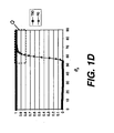
- Figures 1B - 1D the transmission value for light of S-polarization (polarized perpendicular to the plane of incidence and designated by the circles in Figure 1A ) at various acceptance angles ⁇ a is given by curve T90 (filled squares).
- the reflectivity for the orthogonal polarization, or P-polarization (polarized parallel to the plane of incidence and designated by the lines in Figure 1A ) is given by curve R0 (open triangles).
- R0 open triangles
- dashed box Q in Figure 1B good separation of light in the range from 51-90 degrees is desired for polarization of light from the light guide plate. Light separation is considered to be acceptable when both T90 and R0 values exceed about 0.8, indicating that 4:1 or better polarization separation is achieved.
- exemplary values are given for indices n LGP , n e . and n o .
- the depth D is the thickness of the birefringent polarization material.
- the overlap angle range and effective acceptance angle ⁇ a range given in the right-most columns.
- 89 degree value shown in tables and used in description in the present disclosure is used to express an angular value for acceptance angle ⁇ a that can approach 90 degrees as a limit, but is less than 90 degrees.
- the overlapping angle ⁇ is between 71° and 89°, which is about half the desired 51-90 degree range.
- Light between 51 ° and 71 ° is not well-polarized.
- n o 1.389.
- Light guide plate 12 must have an index of refraction n LGP that is substantially equal to the larger of the extraordinary index n e and ordinary index n o .
- the smaller of the extraordinary index n e and ordinary index n o is usually greater than 1.50, which means that the light guide plate must have relatively large index of refraction n LGP , for example, that of polycarbonate, 1.589.
- this is undesirable or unworkable, because the most commonly used light guide plate is made of poly(methyl methacrylate) (PMMA) with index of refraction of around 1.49.
- PMMA poly(methyl methacrylate)
- the invention provides a backlight unit comprising in order:
- the present invention addresses the problem of angular limitation for polarizing light within the light guide plate by using a novel application of formed birefringence.
- Formed birefringence also termed form birefringence, uses devices having generally periodic structures with features and spacing, or pitch dimensions, smaller than a wavelength.
- the formed birefringence principle is used, for example, in wire grid polarizers that use a grating of conductive wires having sufficiently high spatial frequency that zero order light is no longer diffracted and optical path lengths parallel and perpendicular to the grating features are distinct.
- wire-grid polarizer is given in U.S. Patent No. 6,788,461 entitled "Wire Grid Polarizer" to Kurtz et al.
- These conventional solutions employ conductive metal wires or elongated metal layers for polarization. While such devices are capable of providing good separation of polarization states, however, their use of metal materials has unwanted side effects due to some inherent amount of light absorption.
- a layer is formed comprising two dielectric, non-conductive materials, extended in length along the general direction of light propagation, one with a high index of refraction n 1 and the other with a low index of refraction n 2 .
- the two dielectric materials can be isotropic or birefringent.
- the two dielectric materials are isotropic, that is, that each material has only one index of refraction.
- the resulting reflective polarizer of the present invention is structured in such a way that formed birefringence is effected by this arrangement, so that the layer is approximately equivalent in behavior to a layer of highly birefringent material with effective extraordinary index n e and ordinary index n o .
- the effective extraordinary index n e and ordinary index n o that are obtained as a result of the formed birefringent structure are typically different from the indices n 1 and n 2 of the original materials.
- n 1 and n 2 are typically complex numbers for conductive materials, so that the formed birefringence is also a complex number. This arrangement implies some inherent amount of absorption when using conductive materials.
- the reflective polarizer according to this invention has three important advantages that are of particular value for display applications.
- the device provides a high level of birefringence
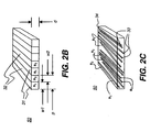
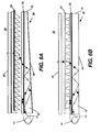
- FIG. 2A shows a backlight apparatus 38 having light guide plate 12 in optical contact with a reflective polarizer 50 based on formed birefringence according to the present invention.
- Light guide plate 12 has an incident face 16 facing light source 14.
- reflective polarizer 50 may be sandwiched between light guide plate 12 and another layer of transparent substrate material, typically a material having the same index of refraction as light guide plate 12.
- Reflective polarizer 50 is in optical contact with light guide plate 12.
- Optical contact as the term is used in the present disclosure, is equivalent to physical contact or, optionally, to coupling through an optical adhesive. There is no air gap between reflective polarizer 50 and light guide plate 12.
- Reflective polarizer 50 has a number of elongated channels 31 and 32, extended in a length direction that is generally perpendicular to incident face 16 and distributed widthwise in an alternating pattern.
- the channels are generally perpendicular if at 90° to the incident face or within ⁇ 15degrees.
- Each channel 31, 32 is formed using a non-conductive or dielectric optical material.
- channels 31 and 32 have different indices of refraction n 1 and n 2 .
- channels 31 and 32 are sub-wavelength in width for light of visible wavelengths, generally less than about 150 nm, and extend along the length of reflective polarizer 20, in a direction parallel to the page, or perpendicular incident face 16.
- the reflective polarizer 50 has efficient extraordinary and ordinary refractive indices n e and n o .
- the direction of the extraordinary refractive index n e is perpendicular to the length direction of channels 31 and 32.
- Index n o then applies for light having a polarization axis that is perpendicular to n e .
- Figure 2B shows some important dimensions that determine the polarization behavior of reflective polarizer 50. These include:
- pitch P is intended to include average pitch, where there may be some variation in pitch as a result of fabrication.
- Figure 2C shows another embodiment of reflective polarizer 50, having a dispersed material 33 embedded within a matrix material 34, arranged in an alternate pattern that can exhibit the same response as the periodic pattern of Figure 2B , but with an aperiodic distribution of channels.
- the dispersed material 33 may have higher or lower index than the matrix material 34.
- the width dimensions of the embedded material are small compared to the wavelength of the visible light, and are preferably smaller than 150 nm, and more preferably smaller than 100 nm. A pitch P of less than 150 nm is preferred.
- the shape of the embedded material is preferably elongated.
- the matrix and dispersed materials can be isotropic or birefringent materials. A large formed birefringence value can also be provided from this configuration.
- the volume fraction of the embedded (or dispersed) material is related to the fill factor f 1 of the reflective polarizer shown in Figure 2B .
- the zero-order value is best applied where the pitch P is very small relative to the wavelengths of incident light, so that: P ⁇ ⁇ 0 Where pitch P ⁇ is not negligible, the second order equations are likely to be more accurate.
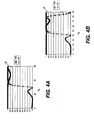
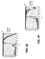
- Figures 4A-4F and 5A-5J show a few examples of the reflective polarizer based on formed birefringence according to the present invention and using some different possible values for indices n LGP , n 1 , n 2 , depth d and fill factor f 1 .
- the pitch P is 140 nm, and the wavelength of interest is 550 nm.
- the pitch P is 100 nm, and the wavelength of interest is also 550 nm.
- Reference dashed box Q shown in Figures 4A-5J shows the range of acceptance angles ⁇ a of interest, here 51-90 degrees and facilitates comparison of the reflective polarizer of the present invention with conventional reflective polarizers as shown earlier in Figures 1B - 1D .
- the high index of refraction n 1 is 2.35
- the low index of refraction n 2 is 1.0.
- the thickness of the reflective polarizer is 0.5 mm.
- this reflective polarizer embodiment of the present invention provides a significant improvement over conventional reflective polarizers such as those described with reference to Figures 1B-1D , with good effective separation of polarization states over a broader range of light acceptance angles ⁇ a .
- Table 2 that follows gives a summary of parameters and performance values that apply for Figures 4A through 4F .
- the depth d and fill factor f 1 values vary from one example to the next.
- the overlapping angle ⁇ a range is between 46° and 82°, wider in the lower bound but not optimal for light at higher angles.
- the overlapping angle ⁇ is between 59° and 77°, which is narrower with respect to both lower and upper bounds.
- the overlapping angle ⁇ is between 51° and 79°, which has about the same lower bound and narrower upper bound.
- the overlapping angle ⁇ is between 50° and 72°, which has about the same lower bound and narrower upper bound.
- the overlapping angle ⁇ is between 51° and 72°, which has about the same lower bound and upper bound as the Figure 4E example.
- FIG. 4B 2.35 1.0 0.50 0.30 46°, 89° 0°,82° 46°, 82° 37° 3
- FIG. 4C 2.35 1.0 0.50 0.50 59°, 89° 0°,77° 59°, 77° 19° 4
- FIG. 4D 2.35 1.0 0.40 0.38 51°, 89° 0°,79° 51°, 79° 29° 5
- FIG. 4E 2.35 1.0 0.60 0.38 50°, 89° 0°,72° 50°, 72° 23° 6
- FIG. 4F 2.35 1.0 5.0 0.38 51°, 89° 0°,72° 51°, 72° 22° Note 1 -
- the ⁇ a range includes all angles in the given overlap range.
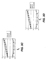
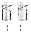
- FIGS. 5A through 5J show performance of a reflective polarizer according to the present invention with slightly different parameters than were given for the examples of Figures 4A through 4F , notably, a different substrate index of refraction n LGP .
- the LGP index of refraction n LGP 1.49, so that that the acceptance angle ⁇ a of light trapped within the light guide is in the range given by about 48° ⁇ ⁇ a ⁇ 90°.
- the most commonly used light guide plate material is PMMA with an index of refraction of around 1.49.
- Reference dashed box Q shown in Figures 5A-5J shows the range of acceptance angles ⁇ a of interest, from about 48-90 degrees, with values for T90 and R0 above 0.8, and facilitates comparison of the reflective polarizer of the present invention with conventional reflective polarizers, as shown earlier in Figures 1B - 1D , and with the inventive examples of Figures 4A through 4F .
- the high index of refraction n 1 is 1.80, and the low index of refraction n 2 is 1.0.
- the pitch P 140 nm.
- the thickness of the reflective polarizer is 0.5 mm.
- reflection R0 exceeds 80% for acceptance angles ⁇ a above about 59°, indicating that light of this polarization is reflected from the reflective polarizer.
- This reflective polarizer design is thus significantly improved over conventional reflective polarizers, but not quite as good as some of the earlier examples given.
- the high index of refraction n 1 is 1.589, which corresponds to that used in the Li et al. '423 disclosure (referring to Figs. 12 and 13 in the '423 disclosure).
- the low index of refraction n 2 is 1.0.
- Transmission T90 is greater than 95% for all acceptance angles ⁇ a .
- Reflection R0 is greater than 80% for acceptance angles above 71°.
- R0 is greater than 50% for 67.5° ⁇ ⁇ a ⁇ 90°.
- this reflective polarizer has comparable polarization separation efficiency to that of conventional reflective polarizers, with the advantage of using a substrate with lower index of refraction (1.49 vs. 1.589).
- performance is at least as good as that described in the Li et al. '423 disclosure, but using standard LGP 12 material (PMMA) rather than the less commonly used polycarbonate material that the Li et al. solution resorts to.
- the overall separation performance is similar to that described in the Li et al. '423 disclosure.
- Figure 5D is similar to that of Figure 5B , but with the high index of refraction n 1 at 2.35.
- FIG. 5B 1.589 1.0 0.5 0.787 71°, 89° 0°, 89° 71°, 89° 29° 9
- FIG. 5C 1.589 1.0 5.0 0.785 69°, 89° 0°, 89° 69°, 89° 21° 10
- FIG. 5D 2.35 1.0 0.5 0.5 69°, 89° 0°, 89° 69°, 89° 21° 11
- FIG. 5E 2.35 1.0 0.5 0.45 62°, 89° 0°, 78° 62°, 78° 17° 12
- FIG. 5F 2.35 1.0 0.5 0.6 89°, 89° 0°, 70° None --- 13
- FIG. 5F 2.35 1.0 0.5 0.6 89°, 89° 0°, 70° None --- 13 FIG.
- FIG. 5G 2.35 1.0 0.4 0.5 72°, 89° 0°, 71° None --- 14 FIG. 5H 2.35 1.0 0.6 0.5 67°, 89° 0°, 70° 67°, 70° 4° 15
- FIG. 5I 1.8 1.0 0.6 0.524 68°, 89° 0°, 84° 58°, 84° 27° 1.6
- FIG. 5J 1.8 1.0 0.6 0.534 59°, 89° 0°, 89° 59°, 89° 31° Note 1 - The ⁇ a range includes all angles in the given overlap range.
- FIGS. 4A-4F and 5A-5J are not limiting but are for illustration purposes. Many other parameter variations would be allowed.
- the shape of channels 31, 32 can be varied from the rectangular cross-section shown in Figures 2A and 2B ; other shapes known in the art can be used as well.
- the pitch P can be longer or shorter, as long as only zero order diffraction occurs.
- the low index material does not need to be air, but could also be any of various materials having a relatively low index of refraction, such as MgF 2 , for example. Both the high and low index materials can also be birefringent, as long as their optic axes are aligned in parallel.
- any of a number of different fabrication techniques could be used for forming reflective polarizer 50.
- the channel structure can be directly patterned into the substrate that will form channels 31 using standard photolithography.
- Other methods could use deposition of material 31 onto the substrate using inkjet printing or other precision deposition techniques.
- a metal layer could be applied as a mask for subsequent etching.
- a metal layer is deposited, using a metal such as aluminum.
- the deposition method can be one of several standard methods including thermal evaporation or sputtering.
- the metal is patterned using standard photolithography followed by a metal etch (possibly dry metal etch such as CC14, BC13) to form a mask pattern. Channels 32 can then be etched to remove unwanted material, leaving the desired void for air.
- etching the dielectric or ion beam milling could be employed.
- Lift off methods can also be used.
- Wet etch using etch compounds such as HF for a SiO2 etch could be used.
- multiple layers of dielectric materials could be deposited to form either or both channels 31 and 32. This type of fabrication would require repeated processes of deposition and etching until the proper depth d ( Figure 2B ) is attained.
- voided air is mixed with an inorganic or organic binder having a suitable index of refraction.
- the medium is then stretched along one direction.
- the dimension of the voided air is smaller than wavelength of light in this direction, and is larger than a few wavelengths of light in the orthogonal direction.
- the relative ratio of voids to binder is equivalent to the fill factor f 1 of the channel, which determines the effective extraordinary and ordinary indices n e and n o .
- Reflective polarizer 50 of the present invention can be used for display backplane illumination in a number of different possible embodiments.
- reflective polarizer 50 is used in optical contact with a tapered light guide plate 30, and a light redirecting film 26 in a display 36.
- This combination of backplane illumination components directs polarized light through LCD modulator 40, enhances light utilizing efficiency, and reduces the requirement for polarization components that are normally provided as part of LCD modulator 40.
- polarization converter such as a quarter-wave film or plate located on the bottom face 18 and/or the end face 19.
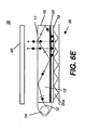
- Figure 6B shows reflective polarizer 50 used in optical contact with a flat or non-tapered light guide plate 12.
- Reflective polarizer 50 can be combined with light guide plate 12 in a number of different possible configurations.
- Figures 6A and 6B show examples in which reflective polarizer 50 is positioned toward the top surface of light guide plate 12.
- Figures 6C, 6D , and 6E show embodiments that position reflective polarizer 50 toward the base of light guide plate 12.
- the location of reflective polarizer 50 of the present invention and the light redirection components appear to be important in order to obtain suitable performance levels with these embodiments.
- Figure 6E shows how light extraction features must be arranged in order to use reflective polarizer 50 effectively if positioned toward the base of light guide plate 12.
- a light extraction structure 25a is placed on the bottom face 18 of the light guide plate 12.
- the reflective polarizer of the present invention provides improved polarization separation over the broad range of angles of light within the light guide plate.
- the reflective polarizer of the present invention provides a high degree of polarization separation in a compact, low-cost component.
Landscapes
- Physics & Mathematics (AREA)
- General Physics & Mathematics (AREA)
- Optics & Photonics (AREA)
- Nonlinear Science (AREA)
- Mathematical Physics (AREA)
- Chemical & Material Sciences (AREA)
- Crystallography & Structural Chemistry (AREA)
- Polarising Elements (AREA)
- Planar Illumination Modules (AREA)
- Liquid Crystal (AREA)
Applications Claiming Priority (1)
| Application Number | Priority Date | Filing Date | Title |
|---|---|---|---|
| US11/760,863 US7618178B2 (en) | 2007-06-11 | 2007-06-11 | Backlight containing formed birefringence reflective polarizer |
Publications (1)
| Publication Number | Publication Date |
|---|---|
| EP2003394A2 true EP2003394A2 (de) | 2008-12-17 |
Family
ID=39705166
Family Applications (1)
| Application Number | Title | Priority Date | Filing Date |
|---|---|---|---|
| EP08252006A Withdrawn EP2003394A2 (de) | 2007-06-11 | 2008-06-11 | Hintergrundlicht mit geformtem Doppelbrechungs-Reflektivpolarisator |
Country Status (6)
| Country | Link |
|---|---|
| US (1) | US7618178B2 (de) |
| EP (1) | EP2003394A2 (de) |
| JP (1) | JP2009087921A (de) |
| KR (1) | KR20080108924A (de) |
| CN (1) | CN101334556B (de) |
| TW (1) | TWI385446B (de) |
Cited By (39)
| Publication number | Priority date | Publication date | Assignee | Title |
|---|---|---|---|---|
| WO2012158574A1 (en) * | 2011-05-13 | 2012-11-22 | Reald Inc. | Efficient polarized directional backlight |
| US8651726B2 (en) | 2010-11-19 | 2014-02-18 | Reald Inc. | Efficient polarized directional backlight |
| US8917441B2 (en) | 2012-07-23 | 2014-12-23 | Reald Inc. | Observe tracking autostereoscopic display |
| US9188731B2 (en) | 2012-05-18 | 2015-11-17 | Reald Inc. | Directional backlight |
| US9237337B2 (en) | 2011-08-24 | 2016-01-12 | Reald Inc. | Autostereoscopic display with a passive cycloidal diffractive waveplate |
| US9235057B2 (en) | 2012-05-18 | 2016-01-12 | Reald Inc. | Polarization recovery in a directional display device |
| US9250448B2 (en) | 2010-11-19 | 2016-02-02 | Reald Inc. | Segmented directional backlight and related methods of backlight illumination |
| US9350980B2 (en) | 2012-05-18 | 2016-05-24 | Reald Inc. | Crosstalk suppression in a directional backlight |
| US9429764B2 (en) | 2012-05-18 | 2016-08-30 | Reald Inc. | Control system for a directional light source |
| US9482874B2 (en) | 2010-11-19 | 2016-11-01 | Reald Inc. | Energy efficient directional flat illuminators |
| US9594261B2 (en) | 2012-05-18 | 2017-03-14 | Reald Spark, Llc | Directionally illuminated waveguide arrangement |
| US9678267B2 (en) | 2012-05-18 | 2017-06-13 | Reald Spark, Llc | Wide angle imaging directional backlights |
| US9709723B2 (en) | 2012-05-18 | 2017-07-18 | Reald Spark, Llc | Directional backlight |
| US9739928B2 (en) | 2013-10-14 | 2017-08-22 | Reald Spark, Llc | Light input for directional backlight |
| US9740034B2 (en) | 2013-10-14 | 2017-08-22 | Reald Spark, Llc | Control of directional display |
| US9835792B2 (en) | 2014-10-08 | 2017-12-05 | Reald Spark, Llc | Directional backlight |
| US9872007B2 (en) | 2013-06-17 | 2018-01-16 | Reald Spark, Llc | Controlling light sources of a directional backlight |
| US10054732B2 (en) | 2013-02-22 | 2018-08-21 | Reald Spark, Llc | Directional backlight having a rear reflector |
| US10062357B2 (en) | 2012-05-18 | 2018-08-28 | Reald Spark, Llc | Controlling light sources of a directional backlight |
| US10126575B1 (en) | 2017-05-08 | 2018-11-13 | Reald Spark, Llc | Optical stack for privacy display |
| US10185076B2 (en) | 2013-11-15 | 2019-01-22 | Reald Spark, Llc | Directional backlights with light emitting element packages |
| US10228505B2 (en) | 2015-05-27 | 2019-03-12 | Reald Spark, Llc | Wide angle imaging directional backlights |
| US10303030B2 (en) | 2017-05-08 | 2019-05-28 | Reald Spark, Llc | Reflective optical stack for privacy display |
| US10321123B2 (en) | 2016-01-05 | 2019-06-11 | Reald Spark, Llc | Gaze correction of multi-view images |
| US10330843B2 (en) | 2015-11-13 | 2019-06-25 | Reald Spark, Llc | Wide angle imaging directional backlights |
| US10356383B2 (en) | 2014-12-24 | 2019-07-16 | Reald Spark, Llc | Adjustment of perceived roundness in stereoscopic image of a head |
| US10359560B2 (en) | 2015-04-13 | 2019-07-23 | Reald Spark, Llc | Wide angle imaging directional backlights |
| US10359561B2 (en) | 2015-11-13 | 2019-07-23 | Reald Spark, Llc | Waveguide comprising surface relief feature and directional backlight, directional display device, and directional display apparatus comprising said waveguide |
| US10393946B2 (en) | 2010-11-19 | 2019-08-27 | Reald Spark, Llc | Method of manufacturing directional backlight apparatus and directional structured optical film |
| US10459321B2 (en) | 2015-11-10 | 2019-10-29 | Reald Inc. | Distortion matching polarization conversion systems and methods thereof |
| US10475418B2 (en) | 2015-10-26 | 2019-11-12 | Reald Spark, Llc | Intelligent privacy system, apparatus, and method thereof |
| US10627670B2 (en) | 2018-01-25 | 2020-04-21 | Reald Spark, Llc | Reflective optical stack for privacy display |
| US10788710B2 (en) | 2017-09-15 | 2020-09-29 | Reald Spark, Llc | Optical stack for switchable directional display |
| US11067736B2 (en) | 2014-06-26 | 2021-07-20 | Reald Spark, Llc | Directional privacy display |
| US11327358B2 (en) | 2017-05-08 | 2022-05-10 | Reald Spark, Llc | Optical stack for directional display |
| US11821602B2 (en) | 2020-09-16 | 2023-11-21 | Reald Spark, Llc | Vehicle external illumination device |
| US11966049B2 (en) | 2022-08-02 | 2024-04-23 | Reald Spark, Llc | Pupil tracking near-eye display |
| US12282168B2 (en) | 2022-08-11 | 2025-04-22 | Reald Spark, Llc | Anamorphic directional illumination device with selective light-guiding |
| US12585094B2 (en) | 2022-06-22 | 2026-03-24 | Reald Spark, Llc | Anamorphic directional illumination device |
Families Citing this family (22)
| Publication number | Priority date | Publication date | Assignee | Title |
|---|---|---|---|---|
| US8130341B2 (en) * | 2009-08-25 | 2012-03-06 | Sharp Kabushiki Kaisha | Uniform diffractive backlight |
| US9016884B2 (en) * | 2010-11-25 | 2015-04-28 | Uk Choi | Polarization illumination system |
| US9091797B2 (en) * | 2011-06-24 | 2015-07-28 | Samsung Electronics Co., Ltd. | Light guide panel, surface light source apparatus including light guide panel, and flat panel display including surface light source apparatus |
| JPWO2013046921A1 (ja) * | 2011-09-27 | 2015-03-26 | 日本電気株式会社 | 偏光子、偏光光学素子、光源および画像表示装置 |
| EP2904446A4 (de) | 2012-10-02 | 2016-06-15 | Reald Inc | Autostereoskopische anzeige mit gestuftem wellenweiter und einem reflektierenden direktionalen element |
| WO2014100753A1 (en) | 2012-12-21 | 2014-06-26 | Reald Inc. | Superlens component for directional display |
| JP2015102796A (ja) * | 2013-11-27 | 2015-06-04 | セイコーエプソン株式会社 | 光分岐装置 |
| CN104503017B (zh) * | 2014-12-26 | 2018-01-16 | 深圳市华星光电技术有限公司 | 导光板、背光模组以及液晶显示装置 |
| RU2596062C1 (ru) | 2015-03-20 | 2016-08-27 | Автономная Некоммерческая Образовательная Организация Высшего Профессионального Образования "Сколковский Институт Науки И Технологий" | Способ коррекции изображения глаз с использованием машинного обучения и способ машинного обучения |
| KR102459467B1 (ko) | 2015-07-17 | 2022-10-27 | 삼성디스플레이 주식회사 | 표시 장치 |
| KR20170039814A (ko) * | 2015-10-01 | 2017-04-12 | 삼성디스플레이 주식회사 | 광학 부품 및 이를 포함하는 표시장치 |
| CN109416431B (zh) | 2016-05-19 | 2022-02-08 | 瑞尔D斯帕克有限责任公司 | 广角成像定向背光源 |
| CN109496258A (zh) | 2016-05-23 | 2019-03-19 | 瑞尔D斯帕克有限责任公司 | 广角成像定向背光源 |
| US10401638B2 (en) | 2017-01-04 | 2019-09-03 | Reald Spark, Llc | Optical stack for imaging directional backlights |
| EP3607387A4 (de) | 2017-04-03 | 2020-11-25 | RealD Spark, LLC | Segmentierte direktionale bildgebungsrückbeleuchtung |
| WO2018230346A1 (ja) * | 2017-06-16 | 2018-12-20 | Jsr株式会社 | 導光板、及び表示装置 |
| ES2967691T3 (es) | 2017-08-08 | 2024-05-03 | Reald Spark Llc | Ajuste de una representación digital de una región de cabeza |
| EP3707554B1 (de) | 2017-11-06 | 2023-09-13 | RealD Spark, LLC | Privatsphärenanzeigevorrichtung |
| CA3089477A1 (en) | 2018-01-25 | 2019-08-01 | Reald Spark, Llc | Touch screen for privacy display |
| KR102440643B1 (ko) | 2018-01-27 | 2022-09-06 | 레이아 인코포레이티드 | 서브파장 격자들을 이용하는 편광 재순환 백라이트, 방법 및 멀티뷰 디스플레이 |
| WO2019217365A1 (en) * | 2018-05-07 | 2019-11-14 | Corning Incorporated | Modified optical microstructures for improved light extraction |
| KR102102888B1 (ko) | 2019-02-28 | 2020-04-21 | 고려대학교 세종산학협력단 | 향상된 fov를 갖는 증강현실 디스플레이 및 그의 웨이브 가이드 장치와 회절 광학 구조체 |
Citations (3)
| Publication number | Priority date | Publication date | Assignee | Title |
|---|---|---|---|---|
| US6285423B1 (en) | 1998-11-27 | 2001-09-04 | National Research Council Of Canada | Polarizing back-lighting system for direct view liquid crystal displays |
| US6443585B1 (en) | 2000-04-25 | 2002-09-03 | Honeywell International Inc. | Hollow cavity light guide for the distribution of collimated light to a liquid crystal display |
| US6788461B2 (en) | 2002-10-15 | 2004-09-07 | Eastman Kodak Company | Wire grid polarizer |
Family Cites Families (6)
| Publication number | Priority date | Publication date | Assignee | Title |
|---|---|---|---|---|
| US6798468B1 (en) * | 1997-09-18 | 2004-09-28 | Seiko Epson Corporation | Display device with a light-reflective polarizer and electronic apparatus employing the same |
| JP2001228474A (ja) * | 2000-02-18 | 2001-08-24 | Mitsubishi Chemicals Corp | 導光体およびバックライト |
| JP3891266B2 (ja) * | 2000-12-28 | 2007-03-14 | 富士電機ホールディングス株式会社 | 導光板及びこの導光板を備えた液晶表示装置 |
| TWI271579B (en) * | 2002-12-04 | 2007-01-21 | Hon Hai Prec Ind Co Ltd | Backlight module |
| JP4593894B2 (ja) * | 2003-09-01 | 2010-12-08 | キヤノン株式会社 | 光学式エンコーダ |
| EP1760500A3 (de) * | 2005-09-02 | 2007-08-01 | Samsung Electronics Co., Ltd. | Beleuchter für ein Flachbildschirmgerät und Beleuchter für ein doppelseitiges Flachbildschirmgerät |
-
2007
- 2007-06-11 US US11/760,863 patent/US7618178B2/en not_active Expired - Fee Related
-
2008
- 2008-06-11 CN CN200810144671XA patent/CN101334556B/zh not_active Expired - Fee Related
- 2008-06-11 EP EP08252006A patent/EP2003394A2/de not_active Withdrawn
- 2008-06-11 JP JP2008153293A patent/JP2009087921A/ja active Pending
- 2008-06-11 KR KR1020080054898A patent/KR20080108924A/ko not_active Ceased
- 2008-06-11 TW TW097121660A patent/TWI385446B/zh not_active IP Right Cessation
Patent Citations (3)
| Publication number | Priority date | Publication date | Assignee | Title |
|---|---|---|---|---|
| US6285423B1 (en) | 1998-11-27 | 2001-09-04 | National Research Council Of Canada | Polarizing back-lighting system for direct view liquid crystal displays |
| US6443585B1 (en) | 2000-04-25 | 2002-09-03 | Honeywell International Inc. | Hollow cavity light guide for the distribution of collimated light to a liquid crystal display |
| US6788461B2 (en) | 2002-10-15 | 2004-09-07 | Eastman Kodak Company | Wire grid polarizer |
Cited By (64)
| Publication number | Priority date | Publication date | Assignee | Title |
|---|---|---|---|---|
| US9482874B2 (en) | 2010-11-19 | 2016-11-01 | Reald Inc. | Energy efficient directional flat illuminators |
| US8651726B2 (en) | 2010-11-19 | 2014-02-18 | Reald Inc. | Efficient polarized directional backlight |
| US10393946B2 (en) | 2010-11-19 | 2019-08-27 | Reald Spark, Llc | Method of manufacturing directional backlight apparatus and directional structured optical film |
| US10473947B2 (en) | 2010-11-19 | 2019-11-12 | Reald Spark, Llc | Directional flat illuminators |
| US9250448B2 (en) | 2010-11-19 | 2016-02-02 | Reald Inc. | Segmented directional backlight and related methods of backlight illumination |
| US9519153B2 (en) | 2010-11-19 | 2016-12-13 | Reald Inc. | Directional flat illuminators |
| WO2012158574A1 (en) * | 2011-05-13 | 2012-11-22 | Reald Inc. | Efficient polarized directional backlight |
| US9237337B2 (en) | 2011-08-24 | 2016-01-12 | Reald Inc. | Autostereoscopic display with a passive cycloidal diffractive waveplate |
| US10175418B2 (en) | 2012-05-18 | 2019-01-08 | Reald Spark, Llc | Wide angle imaging directional backlights |
| US10365426B2 (en) | 2012-05-18 | 2019-07-30 | Reald Spark, Llc | Directional backlight |
| US9350980B2 (en) | 2012-05-18 | 2016-05-24 | Reald Inc. | Crosstalk suppression in a directional backlight |
| US9541766B2 (en) | 2012-05-18 | 2017-01-10 | Reald Spark, Llc | Directional display apparatus |
| US9594261B2 (en) | 2012-05-18 | 2017-03-14 | Reald Spark, Llc | Directionally illuminated waveguide arrangement |
| US9678267B2 (en) | 2012-05-18 | 2017-06-13 | Reald Spark, Llc | Wide angle imaging directional backlights |
| US9709723B2 (en) | 2012-05-18 | 2017-07-18 | Reald Spark, Llc | Directional backlight |
| US9429764B2 (en) | 2012-05-18 | 2016-08-30 | Reald Inc. | Control system for a directional light source |
| US10712582B2 (en) | 2012-05-18 | 2020-07-14 | Reald Spark, Llc | Directional display apparatus |
| US10902821B2 (en) | 2012-05-18 | 2021-01-26 | Reald Spark, Llc | Controlling light sources of a directional backlight |
| US11287878B2 (en) | 2012-05-18 | 2022-03-29 | ReaID Spark, LLC | Controlling light sources of a directional backlight |
| US9910207B2 (en) | 2012-05-18 | 2018-03-06 | Reald Spark, Llc | Polarization recovery in a directional display device |
| US10048500B2 (en) | 2012-05-18 | 2018-08-14 | Reald Spark, Llc | Directionally illuminated waveguide arrangement |
| US9188731B2 (en) | 2012-05-18 | 2015-11-17 | Reald Inc. | Directional backlight |
| US10062357B2 (en) | 2012-05-18 | 2018-08-28 | Reald Spark, Llc | Controlling light sources of a directional backlight |
| US11681359B2 (en) | 2012-05-18 | 2023-06-20 | Reald Spark, Llc | Controlling light sources of a directional backlight |
| US9235057B2 (en) | 2012-05-18 | 2016-01-12 | Reald Inc. | Polarization recovery in a directional display device |
| US8917441B2 (en) | 2012-07-23 | 2014-12-23 | Reald Inc. | Observe tracking autostereoscopic display |
| US10054732B2 (en) | 2013-02-22 | 2018-08-21 | Reald Spark, Llc | Directional backlight having a rear reflector |
| US9872007B2 (en) | 2013-06-17 | 2018-01-16 | Reald Spark, Llc | Controlling light sources of a directional backlight |
| US9739928B2 (en) | 2013-10-14 | 2017-08-22 | Reald Spark, Llc | Light input for directional backlight |
| US10488578B2 (en) | 2013-10-14 | 2019-11-26 | Reald Spark, Llc | Light input for directional backlight |
| US9740034B2 (en) | 2013-10-14 | 2017-08-22 | Reald Spark, Llc | Control of directional display |
| US10185076B2 (en) | 2013-11-15 | 2019-01-22 | Reald Spark, Llc | Directional backlights with light emitting element packages |
| US11067736B2 (en) | 2014-06-26 | 2021-07-20 | Reald Spark, Llc | Directional privacy display |
| US9835792B2 (en) | 2014-10-08 | 2017-12-05 | Reald Spark, Llc | Directional backlight |
| US10356383B2 (en) | 2014-12-24 | 2019-07-16 | Reald Spark, Llc | Adjustment of perceived roundness in stereoscopic image of a head |
| US10359560B2 (en) | 2015-04-13 | 2019-07-23 | Reald Spark, Llc | Wide angle imaging directional backlights |
| US10459152B2 (en) | 2015-04-13 | 2019-10-29 | Reald Spark, Llc | Wide angle imaging directional backlights |
| US11061181B2 (en) | 2015-04-13 | 2021-07-13 | Reald Spark, Llc | Wide angle imaging directional backlights |
| US10634840B2 (en) | 2015-04-13 | 2020-04-28 | Reald Spark, Llc | Wide angle imaging directional backlights |
| US10228505B2 (en) | 2015-05-27 | 2019-03-12 | Reald Spark, Llc | Wide angle imaging directional backlights |
| US10475418B2 (en) | 2015-10-26 | 2019-11-12 | Reald Spark, Llc | Intelligent privacy system, apparatus, and method thereof |
| US11030981B2 (en) | 2015-10-26 | 2021-06-08 | Reald Spark, Llc | Intelligent privacy system, apparatus, and method thereof |
| US10459321B2 (en) | 2015-11-10 | 2019-10-29 | Reald Inc. | Distortion matching polarization conversion systems and methods thereof |
| US10712490B2 (en) | 2015-11-13 | 2020-07-14 | Reald Spark, Llc | Backlight having a waveguide with a plurality of extraction facets, array of light sources, a rear reflector having reflective facets and a transmissive sheet disposed between the waveguide and reflector |
| US11067738B2 (en) | 2015-11-13 | 2021-07-20 | Reald Spark, Llc | Surface features for imaging directional backlights |
| US10330843B2 (en) | 2015-11-13 | 2019-06-25 | Reald Spark, Llc | Wide angle imaging directional backlights |
| US10359561B2 (en) | 2015-11-13 | 2019-07-23 | Reald Spark, Llc | Waveguide comprising surface relief feature and directional backlight, directional display device, and directional display apparatus comprising said waveguide |
| US10750160B2 (en) | 2016-01-05 | 2020-08-18 | Reald Spark, Llc | Gaze correction of multi-view images |
| US10321123B2 (en) | 2016-01-05 | 2019-06-11 | Reald Spark, Llc | Gaze correction of multi-view images |
| US10126575B1 (en) | 2017-05-08 | 2018-11-13 | Reald Spark, Llc | Optical stack for privacy display |
| US11327358B2 (en) | 2017-05-08 | 2022-05-10 | Reald Spark, Llc | Optical stack for directional display |
| US11016318B2 (en) | 2017-05-08 | 2021-05-25 | Reald Spark, Llc | Optical stack for switchable directional display |
| US10303030B2 (en) | 2017-05-08 | 2019-05-28 | Reald Spark, Llc | Reflective optical stack for privacy display |
| US11092851B2 (en) | 2017-09-15 | 2021-08-17 | Reald Spark, Llc | Optical stack for switchable directional display |
| US11181780B2 (en) | 2017-09-15 | 2021-11-23 | Reald Spark, Llc | Optical stack for switchable directional display |
| US10788710B2 (en) | 2017-09-15 | 2020-09-29 | Reald Spark, Llc | Optical stack for switchable directional display |
| US10712608B2 (en) | 2018-01-25 | 2020-07-14 | Reald Spark, Llc | Reflective optical stack for privacy display |
| US10627670B2 (en) | 2018-01-25 | 2020-04-21 | Reald Spark, Llc | Reflective optical stack for privacy display |
| US10976578B2 (en) | 2018-01-25 | 2021-04-13 | Reald Spark, Llc | Reflective optical stack for privacy display |
| US11821602B2 (en) | 2020-09-16 | 2023-11-21 | Reald Spark, Llc | Vehicle external illumination device |
| US12222077B2 (en) | 2020-09-16 | 2025-02-11 | Reald Spark, Llc | Vehicle external illumination device |
| US12585094B2 (en) | 2022-06-22 | 2026-03-24 | Reald Spark, Llc | Anamorphic directional illumination device |
| US11966049B2 (en) | 2022-08-02 | 2024-04-23 | Reald Spark, Llc | Pupil tracking near-eye display |
| US12282168B2 (en) | 2022-08-11 | 2025-04-22 | Reald Spark, Llc | Anamorphic directional illumination device with selective light-guiding |
Also Published As
| Publication number | Publication date |
|---|---|
| US7618178B2 (en) | 2009-11-17 |
| TWI385446B (zh) | 2013-02-11 |
| TW200909945A (en) | 2009-03-01 |
| US20080304282A1 (en) | 2008-12-11 |
| KR20080108924A (ko) | 2008-12-16 |
| CN101334556B (zh) | 2011-10-12 |
| JP2009087921A (ja) | 2009-04-23 |
| CN101334556A (zh) | 2008-12-31 |
Similar Documents
| Publication | Publication Date | Title |
|---|---|---|
| EP2003394A2 (de) | Hintergrundlicht mit geformtem Doppelbrechungs-Reflektivpolarisator | |
| US6996296B2 (en) | Polarizing device | |
| JP3129444B2 (ja) | 導光体、面状光源装置及び液晶表示装置 | |
| JP4838804B2 (ja) | フィルファクターが小さいワイヤグリッド偏光子 | |
| CN106575007B (zh) | 布拉格液晶偏振光栅 | |
| JP2021033049A (ja) | 偏光板及び光学機器 | |
| EP3570081A1 (de) | Mehrschicht-drahtgitterpolarisator | |
| EP1980900A1 (de) | Nanodrahtgitterpolarisator und diesen verwendende Flüssigkristallanzeigevorrichtung | |
| US20070252923A1 (en) | Polarizing light guide plate unit and backlight unit and display device employing the same | |
| KR20040009894A (ko) | 액정 표시 장치 | |
| KR19980071427A (ko) | 백라이트 장치 및 액정표시 장치 | |
| CN101395509A (zh) | 利用内全反射的偏振转向膜 | |
| JP2010262813A (ja) | 照明装置及び液晶表示装置 | |
| CN109491144A (zh) | 液晶显示装置 | |
| KR20170139623A (ko) | 광학 필름 | |
| CN107209313B (zh) | 高对比度逆偏振器 | |
| EP2003475A2 (de) | Lichtumlenkende Vorrichtung | |
| US7425089B2 (en) | Lighting device and image display unit and light guide provided with it | |
| WO2023048086A1 (ja) | 波長板、光学系、および表示装置 | |
| KR970022396A (ko) | 편향 소자 및 그것을 이용한 투사형 표시 장치 | |
| JP2005513535A5 (de) | ||
| CN101185017A (zh) | 显示器照明装置及其制造方法 | |
| CN110709641A (zh) | 包括宽幅转向膜和具有四分之一波长延迟器的反射偏振片的背光源 | |
| WO2009107355A1 (ja) | 紫外線用自己クローニングフォトニック結晶 | |
| JP3683718B2 (ja) | 液晶表示装置 |
Legal Events
| Date | Code | Title | Description |
|---|---|---|---|
| PUAI | Public reference made under article 153(3) epc to a published international application that has entered the european phase |
Free format text: ORIGINAL CODE: 0009012 |
|
| 17P | Request for examination filed |
Effective date: 20080623 |
|
| AK | Designated contracting states |
Kind code of ref document: A2 Designated state(s): AT BE BG CH CY CZ DE DK EE ES FI FR GB GR HR HU IE IS IT LI LT LU LV MC MT NL NO PL PT RO SE SI SK TR |
|
| AX | Request for extension of the european patent |
Extension state: AL BA MK RS |
|
| STAA | Information on the status of an ep patent application or granted ep patent |
Free format text: STATUS: THE APPLICATION HAS BEEN WITHDRAWN |
|
| 18W | Application withdrawn |
Effective date: 20121016 |