EP2003632A2 - Système et procédé de réglage de la sensibilité d'un capteur acoustique - Google Patents
Système et procédé de réglage de la sensibilité d'un capteur acoustique Download PDFInfo
- Publication number
- EP2003632A2 EP2003632A2 EP08158111A EP08158111A EP2003632A2 EP 2003632 A2 EP2003632 A2 EP 2003632A2 EP 08158111 A EP08158111 A EP 08158111A EP 08158111 A EP08158111 A EP 08158111A EP 2003632 A2 EP2003632 A2 EP 2003632A2
- Authority
- EP
- European Patent Office
- Prior art keywords
- signal
- acoustic
- sensitivity
- acoustic detector
- detector
- Prior art date
- Legal status (The legal status is an assumption and is not a legal conclusion. Google has not performed a legal analysis and makes no representation as to the accuracy of the status listed.)
- Ceased
Links
Images


Classifications
-
- G—PHYSICS
- G08—SIGNALLING
- G08B—SIGNALLING SYSTEMS, e.g. PERSONAL CALLING SYSTEMS; ORDER TELEGRAPHS; ALARM SYSTEMS
- G08B13/00—Burglar, theft or intruder alarms
- G08B13/02—Mechanical actuation
- G08B13/04—Mechanical actuation by breaking of glass
-
- G—PHYSICS
- G08—SIGNALLING
- G08B—SIGNALLING SYSTEMS, e.g. PERSONAL CALLING SYSTEMS; ORDER TELEGRAPHS; ALARM SYSTEMS
- G08B13/00—Burglar, theft or intruder alarms
- G08B13/16—Actuation by interference with mechanical vibrations in air or other fluid
- G08B13/1654—Actuation by interference with mechanical vibrations in air or other fluid using passive vibration detection systems
- G08B13/1672—Actuation by interference with mechanical vibrations in air or other fluid using passive vibration detection systems using sonic detecting means, e.g. a microphone operating in the audio frequency range
-
- G—PHYSICS
- G08—SIGNALLING
- G08B—SIGNALLING SYSTEMS, e.g. PERSONAL CALLING SYSTEMS; ORDER TELEGRAPHS; ALARM SYSTEMS
- G08B29/00—Checking or monitoring of signalling or alarm systems; Prevention or correction of operating errors, e.g. preventing unauthorised operation
- G08B29/18—Prevention or correction of operating errors
- G08B29/20—Calibration, including self-calibrating arrangements
- G08B29/22—Provisions facilitating manual calibration, e.g. input or output provisions for testing; Holding of intermittent values to permit measurement
Definitions
- the invention relates to security systems, communication systems and acoustic detectors. More particularly, the invention relates to a method and system for remotely adjusting the sensitivity of an acoustic sensor using a remote control device.
- Acoustic detectors are commonly used to detect and indicate attempts to break into premises.
- the most common acoustic detector is a glass breakage detector.
- the detector generates an alarm signal when the sound of a breaking window is detected.
- the detectors are remotely mounted from the protected glass and are attached to a ceiling or a wall. The location of the detector is dependent on the size of the protected area and a number of other mounting restrictions that are manufacturer specific.
- the detectors rely on detecting the sound of breaking glass by sensing one or more known frequency components associated with the sound of breaking glass.
- the glass break detector When the glass break detector is installed, it is typically tested to ensure proper functionality. Additionally, it is tested to customize the detector for a given location, such that acoustic properties of the proximate environment are compensated for by a sensitivity adjustment to optimize the sensing range of the detector.
- Various common objects found in an indoor location can affect the performance of the detector, such as carpet, ceiling tiles, walls or floors, due to the reflection and absorption of frequency components.
- a glass break simulator is used to simulate the glass breakage.
- United States Patent No. 5,341,122 describes a glass break simulator capable of generating different frequency components indicative of broken glass.
- an installer needs to open the detector each time the level must be changed.
- the sensitivity adjustment can occur several times, requiring the installer to manually adjust the sensitivity each time by changing a switch setting inside the detector. Since each installation is different, the installer would have to climb a ladder and open the detector several times before achieving the proper sensitivity level. This adjustment process is time consuming and cumbersome. Because the process is cumbersome, installers will often not optimize the range for the given site, leading to a less than ideal installation.
- the method of adjusting the sensitivity of an acoustic detector comprises receiving a signal from a remote device, decoding the signal into the operating instruction for the acoustic detector, and adjusting the sensitivity of the acoustic detector according to the operating instruction.
- the signal embodies an operating instruction for the acoustic detector.
- the sensitivity level of the detector can be adjusted by changing a detection threshold.
- the detection threshold is used for alerting the controller or decoder of an acoustic event.
- the detection thresholds are programmed in a controller memory.
- the signal can be any type of wireless signal such as an acoustic signal, RF signal or an infrared signal.
- the signal includes a plurality of pulses separated by spaces in time.
- the acoustic detector decodes the signal by detecting a leading edge of each pulse of the signal, outputting a detection signal indicating the detection of the pulses, determining timings between the detection of each pulse, comparing the timings of the detection with predefined timings, and outputting the instruction based upon the comparison.
- the signal can also instruct the detector to indicate its current sensitivity level.
- the method further includes a step of confirming the adjustment of the sensitivity.
- the confirmation indicates the new sensitivity level.
- the indication can be an audible indication or a visual indication.
- the detector comprises a receiving section for receiving a signal from a wireless remote control device, a decoder for decoding the signal into a control signal, and a controller for changing the sensitivity level of a sensor based upon the control signal.
- the decoder comprises a storage device for storing a plurality of preset patterns and corresponding instructions, a comparator for matching the decoded pattern to one of said plurality of preset patterns, and an output device for outputting one of the predefined instructions, which corresponds to a matched pattern.
- Each preset pattern is associated with a predefined instruction.
- One preset pattern corresponds to an instruction to decrease the sensitivity of the sensing element and a second preset pattern corresponds to increase the sensitivity of the sensing element.
- Another preset pattern corresponds to a signal instructing the acoustic detector to confirm the setting.
- the detector also includes a notification device for indicating a current sensitivity setting of a sensing element.
- the notification device can include a light source such as an LED. A specific pattern of light indicates the current sensitivity setting.
- a system for controlling the sensitivity of an acoustic detector comprising a remote control device and an acoustic detector.
- the system comprises a remote control device that generates and transmits a signal to the acoustic detector.
- the signal embodies an operating instruction for the acoustic detector.
- the signal comprising a plurality of pulses separated by predefined spaces in time.
- the acoustic detector comprises a receiving section for receiving the signal, a decoder for decoding the signal into an operating instruction, and a controller for adjusting the sensitivity of a sensor according to the operating instruction.
- a remote control device can be an acoustic simulator.
- the remote control device can also be a security system keypad.
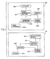
- Figure 1 illustrates a basic diagram of the remote control system of the invention including a block diagram of a remote control device and a block diagram of an acoustic detector according to an embodiment of the invention
- Figure 2 illustrates a block diagram of the decoder according to an embodiment of the invention
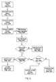
- Figure 3 illustrates a sensitivity adjustment method according to an embodiment of the invention
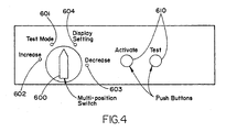
- Figure 4 is an exemplary user interface for the remote control device
- Figure 5 is another exemplary user interface for the remote control device.
- Figure 1 illustrates the remote control system in which a remote control device 100 is used to adjust the sensitivity of an acoustic detector 110.
- the remote control device 100 can be any device capable of transmitting a calibrated acoustic signal.
- the remote control device 100 is a glass break simulator.
- the remote control device 100 can be the glass break simulator as described in U.S. Patent 5,341,122 issued to Stephen Rickman , which is hereby incorporated by reference.
- the remote control device 100 may be configured to generate a control signal to control specific features of an acoustic detection.
- the remote control device 100 includes a user interface section 200 adapted to allow a user to input a control instruction.
- the user interface section 200 can be a DIP switch, a jog dial, or an arrow key or button. Alternatively, the user interface section 200 can be an alphanumeric keypad.
- the remote control device 100 also includes an interface decoder 205.
- the interface decoder 205 is coupled to the user interface section 200 to detect and decode the user input from the user interface section (200). For example, if the alphanumeric keypad is used as the user interface section 200, the interface decoder 205 determines which key is pressed. This determination will use a known method for detecting a key depression. The determination process will not be described herein.
- the interface decoder 205 can use the same process for arrow keys.
- the interface decoder 205 determines a direction of revolution and magnitude based upon a relative voltage. The detection of the rotation of a jog dial is also known and will not be described.
- the interface decoder 205 will detect the opening or closing of the switch or relays.
- the remote control device includes an acoustic signal generating section 210 and memory 215.
- the acoustic signal generator section 210 generates a predefined acoustic signal based upon the user input detected by the interface decoder 205.
- the predefined acoustic signal is retrieved from memory 215.
- the memory 215 includes a database or lookup table of a plurality of predefined acoustic signals.
- different acoustic signals will have different patterns defined by different space or timing between elements. Each pattern corresponds to a different control instruction or function.
- the encoded acoustic signal can be the acoustic signal described by U.S. Patent 5,524,099, issued to Stephen Rickman , which is hereby incorporated by reference.
- the encoded acoustic signal is a series of spaced-apart pulses encoded by a relative inter pulsed timing of the spaced apart pulses.
- the acoustic signal generating section 210 encodes the signal with the relative timing; the encoding instructions and pulses are stored in memory entered by control function.
- the memory section 215 contains set timings and pulses for increasing or decreasing the sensitivity of an acoustic detector 110. Additionally, the memory section 215 can contain a set timing and pulses for instructing the acoustic detector 110 to indicate its current sensitivity level.
- the remote control device 100 also includes a speaker 220 and a power supply 225.
- the speaker is used to transmit the encoded acoustic control signal to the acoustic detector 110.
- the power supply can be a battery.
- the acoustic detector 110 includes an acoustic sensor 300, acoustic signal decoder 305 and a control section 310.
- the acoustic sensor 300 can be a microphone.
- the acoustic sensor 300 senses the encoded acoustic signal from the remote control device 100.
- the decoder 305 decodes the encoded acoustic signal.
- the control section 310 can be a microprocessor.
- Figure 3 illustrates that the decoder is separate from the control section; however, the two can be integrated.
- the acoustic detector 110 also includes a notification section 315.
- the notification section 315 can be an LED or a speaker.
- the notification section 315 is used to indicate the current sensitivity level for the sensor 300. Additionally, the notification section 315 can be used as a confirmation of the receipt of the acoustic signal or of a setting of the new sensitivity level.
- the acoustic detector 110 includes an internal power source such as a battery. In another embodiment, the acoustic detector 110 can be powered via a wired power source from a security panel.
- the encoded acoustic signal is decoded in the manner as described in U.S. Patent No. 5,524,099 to Rickman .
- FIG. 2 illustrates an exemplary decoder 305 according to the invention.
- the decoder 305 comprises a pulse recognizer 400 coupled to a timer 405.
- the pulse recognizer 400 generates an output signal for each recognized acoustic pulse.
- the timer 405 receives the output signal and measures the time between received output signals.
- the decoder 305 further includes a comparing section 410 that compares the measured times, that are measured by the timer 405 to predefined time values.
- the predefined time values are stored in a storage section 415 in advance.
- the storage section can be memory. Based upon the result of the comparison, the decoder 305 outputs a preset signal to the control section 310.
- the preset signal is also stored in the storage section 415.
- Software in the decoder executes the decoding process on the encoded acoustic signal
- control section 310 Upon receipt of this preset signal, the control section 310 executes the desired control instruction, e.g., change a threshold value used for detection of an acoustic sound.
- desired control instruction e.g., change a threshold value used for detection of an acoustic sound.
- Figure 3 illustrates a flow chart of the remote control method according to an embodiment of the invention.
- the installer or user inputs an instruction into the remote control device 100 via the user interface 200.
- the interface detector 205 decodes the input, at step 500.
- the decoding method is based upon the type of user interface 200.
- the signal generating section 210 generates the encoded acoustic signal based upon the decoded input.
- the interface detector 205 forwards the decoded input signal to the signal generating section 210.
- the signal generating section 210 retrieves from memory 205 the corresponding instruction signal.
- the memory contains digitized waveforms for sound generation of the acoustic signal, i.e., pulses.
- the signal generating section selects the acoustic pattern and outputs the signal to the speaker 225.
- the encoded acoustic signal is transmitted to the acoustic detector 110, at step 520.
- the signal contains the pulses and spaces.
- a timer determines the timing of the pulses and spaces.
- the acoustic detector 110 receives the encoded acoustic signal.
- the sensor 300 or microphone detects the sound.
- the acoustic detector 110 can acknowledge the encoded acoustic signal.
- the notification device 315 acknowledges the encoded acoustic signal.
- the acknowledgement can be in the form of a visual indication, e.g., flashing lights. Alternatively, an audible acknowledgement can be used.
- the acoustic detector 110 decodes the encoded acoustic signal.
- the pulse recognizer 400 recognizes a pulse if the acoustic signal exceeds a detection threshold.
- the detection threshold is used to determine whether an acoustic event has occurred. If the amplitude of a pulse is greater than the detection threshold, it is an event that will be evaluated by the control section 310.
- the sensitivity of the acoustic detector, as used therein refers to a detection threshold. A low threshold value corresponds to a high sensitivity of the sensor.
- the pulse recognizer 400 outputs a signal.
- a timer 405 tracks the output of the pulse recognizer 400 and determines the timing of the pulses and spaces. The timing pattern is compared with timings from the storage section 415.
- the decoder 305 determines whether the timing pattern matched any prestored pattern. In one embodiment, if no match is found, the notification device 315 indicates an error, at step 550. In another embodiment, if no match is found, the acoustic detector 110 will assume that the signal is noise and no action will be taken. The user will resend the control signal. Additionally, the acoustic detector determines whether the acoustic signal is an acoustic event, i.e., glass breakage. If the amplitude of the signal and pattern indicated an event indicative of an intrusion attempt, the acoustic detector 110 will generate an alarm (not shown).
- the decoder 305 determines whether the signal is an instruction for a sensitivity adjustment, at step 555. At least two signal patterns indicate a sensitivity adjustment. If the signal is an instruction to adjust the sensitivity, the decoder 305 outputs an adjustment signal to the control section 310. At step 560, the control section 310 changes the detection threshold according to the adjustment signal. For example, if the instruction is to increase the sensitivity, the control section 310 changes the detection threshold to a lower value. On the other hand, if the instruction is to decrease the sensitivity, the control section 310 changes the detection threshold to a high value. Each increase or decrease instruction causes the control section 310 to change the detection threshold by one level.
- the acoustic detector has four sensitivity levels, i.e., four detection thresholds.
- the detection thresholds are stored in memory in the control section 310. Once the detection threshold value is set, the control section 305 can confirm the adjustment, at step 565.
- the notification device 315 can indicate the new sensitivity level, e.g., flashing a light in a specific manner.
- the decoder 305 determines if the signal is an instruction for the acoustic detector 110 to indicate the current sensitivity level, at step 570.
- the decoder 305 If the acoustic signal is an instruction for the acoustic detector 110 to indicate the current sensitivity level, the decoder 305 outputs a status instruction to the control section 310. The notification device 315 will then indicate the current sensitivity level, e.g., flashing a light in a specific manner, at step 575.
- the decoder If the acoustic signal is neither an instruction for adjusting the sensitivity nor an instruction for indicating a current sensitivity level, the decoder outputs a signal corresponding to the intended control function and the control section performs the intended control function at step 580.
- the function can be a mode selection.
- the control method according to the invention eliminates the need for any sensitivity switches in the acoustic detector 110.
- Figure 4 illustrates one exemplary user interface 200 for the remote device 100.
- the user interface 200 includes a multi-position switch 600 and several push buttons 610.
- the multi-position switch 600 includes four settings: test mode 601, increase 602, decrease 603 and display setting 604.
- Figure 5 illustrates another exemplary user interface 200.
- the user interface 200 includes a plurality of push buttons and LED indicators.
- the user interface 200 can include a push button for setting a mode of the device 705.
- the mode is indicated by led indictors 700: one for a test mode and another for a set mode.
- the user interface 200 can also include a push button for a testing the acoustic detector 110 which arms the remote control device 100 for a full acoustic test 715 in one mode and in a second mode triggers the remote control device 100 to send a status instruction to the acoustic detector 110.
- the user interface will have a corresponding LED indicator 715 for the test.
- buttons 720 and 725 for adjusting the sensitivity of the acoustic detector in one mode and controlling test features in a second.
- Button 720 in test mode, will cause the remote control device 100 to send a signal to the acoustic detector 110 to toggle in and out of test mode.
- Button 720 in set mode, will cause the remote control device 100 to send an acoustic signal to the acoustic detector 110 which is an instruction to increase the sensitivity.
- Button 725 in test mode, will cause the remote control device 100 to send an acoustic test signal to the acoustic detector 110 which simulates a glassbreak.
- Button 725 in set mode, will cause the device to send an acoustic signal to the acoustic detector 110 which is an instruction to decrease the sensitivity.
- This exemplary user interface might be used when the remote control device 100 is a glassbreak simulator.
- the acoustic detector 110 increases or decreases the sensitivity level (threshold) one level for each control instruction, i.e., one encoded acoustic signal; however, in another embodiment, the remote control device can transmit a single encoded acoustic signal that causes the acoustic detector 110 to set a maximum sensitivity or a minimum sensitivity level.
- the control section 310 can modify the gain of an amplifier that is used to amplify the signal from the sensor 300.
- a sensor 300 drives a bandpass amplifier.
- the bandpass filter has a predefined center frequency and preset gain at the center frequency. The preset gain can be adjusted to increase or decrease the sensitivity of the sensor, without changing the detection threshold.
- the encoded signal has been described as an encoded acoustic signal in the preferred embodiment, in another embodiment the encoded signal can be any wireless signal such as a RF signal or an infrared signal.
- the remote control device 100 will include an infrared transmitter and the acoustic detector 110 will include an infrared detector.
- the infrared detector can be an infrared diode.
- the infrared transmitter and infrared detector will be configured such that the emitting frequency of the transmitter and the detection frequency of the detector match, i.e., have the same center frequency.
- the infrared signal has the same pattern of pulses and spaces therebetween and, therefore, a similar decoder can be used.
- the remote control device 100 will include an RF transmitter and the acoustic detector will include an RF detector.
- the RF signal includes a predefined signal pattern of pulses and spaces therebetween, as described above. The same decoder can be used to decode the RF signal.
- An installer can use the remote sensitivity adjustment method during installation.
- an owner of the acoustic detector can adjust the sensitivity of the detector after installation, if the acoustic properties of the room change.
- the adjustment process is only part of the configuration and calibration process.
- the calibration process will also include a simulation of the sound of glass breaking. The results of the simulation affects whether the installer changes the sensitivity. For example, the installer will activate a test mode by depressing buttons on the simulator (e.g., 610).
- the acoustic detector 110 receives the activation signal and decodes the signal as described above.
- the control section 310 causes the acoustic detector 110 to enter test mode and the notification device 315 will confirm the mode. The installer then moves to the furthest point on a glass that is being protected and will generate an acoustic sound that simulates the sound of glass breaking.
- the speaker 225 of the simulator (e.g., remote control device 100) is pointed toward the acoustic detector 110. If the acoustic detector 110 does not detect the acoustic sound, e.g., amplitude of the received sound is not greater than the detection threshold; the installer can increase the sensitivity, e.g., lower threshold, as described above, i.e., initiate an increase sensitivity signal. An encoded signal will be transmitted from the remote control device 100, e.g., simulator. The detector will change the sensitivity, e,g., detection threshold and the installer will repeat the process, i.e., resend the same acoustic sound. The sensitivity of the acoustic detector will be changed until the acoustic sound is detected or until a maximum sensitivity is reached.
- the remote control device 100 can be a keypad associated with a security system.
- the keypad can broadcast an acoustic signal. This provides an advantage of enabling a user to adjust the sensitivity of the acoustic detector 110 using his or her security keypad. For example, if a thick carpet is added or new furniture is added to the room, the acoustic properties of the room will change. The additions will change signal reflection and absorption that might interfere with the detection of an acoustic sound.
- the acoustic signal can be pre-installed into a keypad or uploaded from a remote monitoring center.
- the remote control device 100 can be a wireless handheld keyfob.
Landscapes
- Physics & Mathematics (AREA)
- General Physics & Mathematics (AREA)
- Engineering & Computer Science (AREA)
- Multimedia (AREA)
- Computer Security & Cryptography (AREA)
- Selective Calling Equipment (AREA)
- Burglar Alarm Systems (AREA)
- Measurement Of Mechanical Vibrations Or Ultrasonic Waves (AREA)
Applications Claiming Priority (1)
| Application Number | Priority Date | Filing Date | Title |
|---|---|---|---|
| US11/761,719 US8199608B2 (en) | 2007-06-12 | 2007-06-12 | System and method for adjusting sensitivity of an acoustic sensor |
Publications (2)
| Publication Number | Publication Date |
|---|---|
| EP2003632A2 true EP2003632A2 (fr) | 2008-12-17 |
| EP2003632A3 EP2003632A3 (fr) | 2009-08-19 |
Family
ID=39643890
Family Applications (1)
| Application Number | Title | Priority Date | Filing Date |
|---|---|---|---|
| EP08158111A Ceased EP2003632A3 (fr) | 2007-06-12 | 2008-06-12 | Système et procédé de réglage de la sensibilité d'un capteur acoustique |
Country Status (4)
| Country | Link |
|---|---|
| US (1) | US8199608B2 (fr) |
| EP (1) | EP2003632A3 (fr) |
| CN (1) | CN101324984B (fr) |
| CA (1) | CA2634330A1 (fr) |
Cited By (1)
| Publication number | Priority date | Publication date | Assignee | Title |
|---|---|---|---|---|
| EP2461299A3 (fr) * | 2010-12-06 | 2015-07-29 | E.I. Technology Limited | Test de dispositif d'alarme utilisant des messages acoustiques à codage temporel |
Families Citing this family (14)
| Publication number | Priority date | Publication date | Assignee | Title |
|---|---|---|---|---|
| US8731864B2 (en) * | 2011-05-11 | 2014-05-20 | Honeywell International Inc. | System and method of sensor installation validation |
| US20120293329A1 (en) * | 2011-05-20 | 2012-11-22 | James Vernon Cunningham | Wireless dog barking alarm system |
| US20130076506A1 (en) * | 2011-09-23 | 2013-03-28 | Honeywell International Inc. | System and Method for Testing and Calibrating Audio Detector and Other Sensing and Communications Devices |
| US8964509B2 (en) * | 2011-12-21 | 2015-02-24 | Utc Fire & Security Corporation | Remote communication and control of acoustic detectors |
| US20130170323A1 (en) * | 2012-01-03 | 2013-07-04 | Richard Alan Smith | Method and System for Audio Detector Mode Activation |
| US9542787B2 (en) | 2013-03-15 | 2017-01-10 | De La Rue North America Inc. | Systems and methods for detecting a document attribute using acoustics |
| US9349269B2 (en) * | 2014-01-06 | 2016-05-24 | Tyco Fire & Security Gmbh | Glass breakage detection system and method of configuration thereof |
| US9384641B2 (en) * | 2014-09-30 | 2016-07-05 | Tyco Fire & Security Gmbh | Glass breakage detection system and method |
| CN106910326B (zh) * | 2015-12-22 | 2021-04-27 | 安定宝公司 | 报警设备校准方法及系统 |
| US10996325B2 (en) * | 2018-11-30 | 2021-05-04 | Ademco Inc. | Systems and methods for adjusting a signal broadcast pattern of an intrusion detector |
| US11074794B2 (en) | 2018-11-30 | 2021-07-27 | Ademco Inc. | Systems and methods for activating and deactivating controlled devices in a secured area |
| US11226256B2 (en) * | 2019-04-05 | 2022-01-18 | Honeywell International Inc. | Handheld ultrasonic testing device |
| US10762773B1 (en) | 2019-08-19 | 2020-09-01 | Ademco Inc. | Systems and methods for building and using a false alarm predicting model to determine whether to alert a user and/or relevant authorities about an alarm signal from a security system |
| CN112735400A (zh) * | 2020-12-01 | 2021-04-30 | 西安中星测控有限公司 | 一种语音识别智能传感器 |
Citations (3)
| Publication number | Priority date | Publication date | Assignee | Title |
|---|---|---|---|---|
| US5341122A (en) | 1992-06-22 | 1994-08-23 | C & K Systems, Inc. | Pressure actuated glass break simulator |
| US5524099A (en) | 1994-05-25 | 1996-06-04 | C & K Systems, Inc. | Intrusion detector operating mode selection system |
| US20070008125A1 (en) * | 2004-06-17 | 2007-01-11 | Smith Richard A | Method of eliminating impact/shock related false alarms in an acoustical glassbreak detector |
Family Cites Families (10)
| Publication number | Priority date | Publication date | Assignee | Title |
|---|---|---|---|---|
| GB1167142A (en) | 1965-08-31 | 1969-10-15 | Tayside Electronics | Alarm Systems. |
| US5640143A (en) | 1995-02-06 | 1997-06-17 | Mytech Corporation | Occupancy sensor and method of operating same |
| US6028505A (en) * | 1996-03-27 | 2000-02-22 | Clifford Electronics, Inc. | Electronic vehicle security system with remote control |
| CH694839A5 (de) | 2000-05-22 | 2005-07-29 | Hts High Technology Systems Ag | Fernbedienung von Bewegungs- und/oder Präsenzmeldern. |
| US6885300B1 (en) * | 2002-06-05 | 2005-04-26 | The Watt Stopper, Inc. | Broad field motion detector |
| CN2586144Y (zh) * | 2002-12-16 | 2003-11-12 | 王胜平 | 次声探测器 |
| US20050128067A1 (en) * | 2003-12-11 | 2005-06-16 | Honeywell International, Inc. | Automatic sensitivity adjustment on motion detectors in security system |
| WO2006073483A2 (fr) | 2005-01-05 | 2006-07-13 | Honeywell International Inc. | Procede permettant de changer a distance la sensibilite d'un capteur sans fil |
| US7636039B2 (en) * | 2004-11-29 | 2009-12-22 | Honeywell International Inc. | Motion detector wireless remote self-test |
| US20060238337A1 (en) * | 2005-04-20 | 2006-10-26 | Dei Headquarters, Inc. | Security system with remote control and proximity detector |
-
2007
- 2007-06-12 US US11/761,719 patent/US8199608B2/en not_active Expired - Fee Related
-
2008
- 2008-06-06 CA CA002634330A patent/CA2634330A1/fr not_active Abandoned
- 2008-06-12 CN CN2008101314509A patent/CN101324984B/zh not_active Expired - Fee Related
- 2008-06-12 EP EP08158111A patent/EP2003632A3/fr not_active Ceased
Patent Citations (3)
| Publication number | Priority date | Publication date | Assignee | Title |
|---|---|---|---|---|
| US5341122A (en) | 1992-06-22 | 1994-08-23 | C & K Systems, Inc. | Pressure actuated glass break simulator |
| US5524099A (en) | 1994-05-25 | 1996-06-04 | C & K Systems, Inc. | Intrusion detector operating mode selection system |
| US20070008125A1 (en) * | 2004-06-17 | 2007-01-11 | Smith Richard A | Method of eliminating impact/shock related false alarms in an acoustical glassbreak detector |
Cited By (1)
| Publication number | Priority date | Publication date | Assignee | Title |
|---|---|---|---|---|
| EP2461299A3 (fr) * | 2010-12-06 | 2015-07-29 | E.I. Technology Limited | Test de dispositif d'alarme utilisant des messages acoustiques à codage temporel |
Also Published As
| Publication number | Publication date |
|---|---|
| CN101324984B (zh) | 2012-07-04 |
| EP2003632A3 (fr) | 2009-08-19 |
| US20080310254A1 (en) | 2008-12-18 |
| CA2634330A1 (fr) | 2008-12-12 |
| US8199608B2 (en) | 2012-06-12 |
| CN101324984A (zh) | 2008-12-17 |
Similar Documents
| Publication | Publication Date | Title |
|---|---|---|
| US8199608B2 (en) | System and method for adjusting sensitivity of an acoustic sensor | |
| EP2008256B1 (fr) | Liaison sans fil d'unités de détection de fumée/co | |
| US5640143A (en) | Occupancy sensor and method of operating same | |
| US6522248B1 (en) | Multicondition detection apparatus and method providing interleaved tone and verbal warnings | |
| EP2693414B1 (fr) | Dispositif d'alarme et système d'alarme | |
| US7796033B2 (en) | System and method for calibrating a microwave motion detector | |
| US7636039B2 (en) | Motion detector wireless remote self-test | |
| US6593850B1 (en) | Wireless intrusion detector with test mode | |
| EP2023305B1 (fr) | Système et procédé pour ajustement de sensibilité automatique d'un détecteur acoustique | |
| WO2009073288A2 (fr) | Thermostat avec interconnexion sonore aux détecteurs de menaces | |
| WO2007101984A1 (fr) | Système d'alarme | |
| EP2037423B1 (fr) | Appareil et procédé pour l'étalonnage d'un système de détection acoustique | |
| GB2498263A (en) | Remotely changing a mode of operation and adjusting a sensitivity level of a glass break detector | |
| JP2002042281A (ja) | 安否判別装置と安否判定装置及び通報装置 | |
| JP2005510100A (ja) | 電気器具の作動を制御するための方法及び装置 | |
| AU2001244305A1 (en) | Infra-red detector | |
| KR101071118B1 (ko) | 리모콘 위치 지시 시스템 | |
| JP2001116254A (ja) | 火炎監視装置 | |
| KR0184067B1 (ko) | 방범경보 겸용 다중회선 원격 제어장치의 제어방법 | |
| JP2019012007A (ja) | 検知装置 | |
| JPH10132928A (ja) | 移動体検知方法及び移動体検知装置 | |
| JP2018205997A (ja) | 警報器 |
Legal Events
| Date | Code | Title | Description |
|---|---|---|---|
| PUAI | Public reference made under article 153(3) epc to a published international application that has entered the european phase |
Free format text: ORIGINAL CODE: 0009012 |
|
| AK | Designated contracting states |
Kind code of ref document: A2 Designated state(s): AT BE BG CH CY CZ DE DK EE ES FI FR GB GR HR HU IE IS IT LI LT LU LV MC MT NL NO PL PT RO SE SI SK TR |
|
| AX | Request for extension of the european patent |
Extension state: AL BA MK RS |
|
| PUAL | Search report despatched |
Free format text: ORIGINAL CODE: 0009013 |
|
| AK | Designated contracting states |
Kind code of ref document: A3 Designated state(s): AT BE BG CH CY CZ DE DK EE ES FI FR GB GR HR HU IE IS IT LI LT LU LV MC MT NL NO PL PT RO SE SI SK TR |
|
| AX | Request for extension of the european patent |
Extension state: AL BA MK RS |
|
| 17P | Request for examination filed |
Effective date: 20100209 |
|
| AKX | Designation fees paid |
Designated state(s): DE ES FR GB |
|
| 17Q | First examination report despatched |
Effective date: 20110906 |
|
| STAA | Information on the status of an ep patent application or granted ep patent |
Free format text: STATUS: THE APPLICATION HAS BEEN REFUSED |
|
| 18R | Application refused |
Effective date: 20161206 |