EP2003635A2 - Affichage lumineux et procédé de fabrication d'un affichage lumineux - Google Patents
Affichage lumineux et procédé de fabrication d'un affichage lumineux Download PDFInfo
- Publication number
- EP2003635A2 EP2003635A2 EP08157951A EP08157951A EP2003635A2 EP 2003635 A2 EP2003635 A2 EP 2003635A2 EP 08157951 A EP08157951 A EP 08157951A EP 08157951 A EP08157951 A EP 08157951A EP 2003635 A2 EP2003635 A2 EP 2003635A2
- Authority
- EP
- European Patent Office
- Prior art keywords
- light
- elements
- housing
- illuminated display
- display
- Prior art date
- Legal status (The legal status is an assumption and is not a legal conclusion. Google has not performed a legal analysis and makes no representation as to the accuracy of the status listed.)
- Withdrawn
Links
Images



Classifications
-
- G—PHYSICS
- G09—EDUCATION; CRYPTOGRAPHY; DISPLAY; ADVERTISING; SEALS
- G09F—DISPLAYING; ADVERTISING; SIGNS; LABELS OR NAME-PLATES; SEALS
- G09F9/00—Indicating arrangements for variable information in which the information is built-up on a support by selection or combination of individual elements
- G09F9/30—Indicating arrangements for variable information in which the information is built-up on a support by selection or combination of individual elements in which the desired character or characters are formed by combining individual elements
-
- G—PHYSICS
- G09—EDUCATION; CRYPTOGRAPHY; DISPLAY; ADVERTISING; SEALS
- G09F—DISPLAYING; ADVERTISING; SIGNS; LABELS OR NAME-PLATES; SEALS
- G09F9/00—Indicating arrangements for variable information in which the information is built-up on a support by selection or combination of individual elements
- G09F9/30—Indicating arrangements for variable information in which the information is built-up on a support by selection or combination of individual elements in which the desired character or characters are formed by combining individual elements
- G09F9/33—Indicating arrangements for variable information in which the information is built-up on a support by selection or combination of individual elements in which the desired character or characters are formed by combining individual elements being semiconductor devices, e.g. diodes
Definitions
- the present invention relates to a light-emitting display, in particular for displaying characters, symbols and / or images, comprising a housing, a support and a plurality of light elements arranged on the support for generating visible electromagnetic radiation, which housing has at least one at least partially open display side and which carrier is arranged on the housing such that radiation generated by at least a part of the plurality of luminous elements radiates in a direction away from the display side direction.
- the invention further relates to a method for producing a light display, in particular for displaying characters, symbols and / or images, comprising providing a housing having at least one at least partially open display side, a carrier and a plurality of light elements for generating visible electromagnetic radiation Arranging the plurality of luminous elements on the support and the support in the housing such that at least part of the radiation generated by the plurality of luminous elements radiates in a direction away from the display side.
- LEDs LEDs
- SMD LEDs surface mounted device
- the translucent cover material makes it possible, on the one hand, to protect the electronic components required for forming the illuminated display, in particular the lighting elements, from the effects of the weather.
- a structure of the light display is more stable overall than conventional light-emitting displays, the electronic components are usually placed behind a protected disc.
- the cover material optionally allows the lighting elements to be covered in one manufacturing step and, apart from their electrical connection, securely connected to the carrier.
- the inventively proposed Training particularly thin light indicators are made, since no elaborate holder is required for example for a disc.
- the housing and the carrier can also be integrally formed, which in particular has the advantage that at the same time the housing can be completely sealed by covering the lighting elements with the covering material.
- the carrier separate from the housing can also be connected to the housing. This can be done by means of conventional fasteners, for example, arranged on the parts to be joined and cooperating locking members of locking connections or by screws.
- the cover material may also serve to connect the carrier to the housing or to additionally strengthen a mechanical connection thereof.
- the carrier connected to the cover material is arranged fluid-tight in the housing. As already explained, this can optionally also be realized by means of the covering material.
- the covering material is a potting compound, which is preferably free-flowing during processing and curable after processing.
- a curing potting compound makes it possible in a single step to shed the carrier with the luminous elements disposed thereon fluid-tight and so to protect the components arranged on the support from the weather, which is exposed to the light indicator when it is used outdoors.
- the carrier can also be cast with the components in the housing.
- the illuminated display is designed such that the carrier with the at least one display side associated lighting elements and the housing with the potting compound are completely shed.
- the carrier with the at least one display side associated lighting elements and the housing with the potting compound are completely shed.
- fluids can undesirably come into contact with the lighting elements or other electronic components.
- a corrosion of electrical lines, in particular of electrically conductive contacts on components, the carrier and / or the housing is prevented, which may affect a function of the illuminated display.
- the outer surface defined by the cover material is flat. This facilitates, in particular, further processing of the outer surface, for example printing on the same. Furthermore, a risk of injury to persons who can come into contact with the light display, practically excluded.
- the illuminated display can be covered with the cover material or cast with the potting compound, if the housing is trough-shaped and has a peripheral edge.
- the casting compound can be poured in a flowable state from the display side so on the support and in the preferably horizontally disposed housing until it is completely filled with the potting compound.
- the at least one display page is completely open.
- a complete housing side can be used completely as an indicator.
- the outer surface defined by the cover material then defines the display side.
- the housing In order to be able to form plate-shaped illuminated displays, which can optionally also be connected to form a plurality of units, it is expedient for the housing to be cuboidal.
- a height of the light display is then usually defined by a height of the housing, so for example, a height of a peripheral edge of a cuboidal trough.
- connection device can be cast with the potting compound with the carrier and / or the housing, which allows a total of a particularly compact and stable construction of the light indicator.
- the connecting device is advantageously arranged on a rear side of the housing facing away from the display side.
- the majority of the lighting elements defines a quadrangular and / or round emitting surface.
- a square radiating surface allows a particularly high luminance of the light indicator as a whole.
- the outer surface is at least partially covered with at least one antireflection layer.
- the at least one antireflection coating completely covers the outer surface. Thus, in particular in areas in which radiation emerges from the illuminated display, reflections are prevented or at least minimized.
- the antireflection layer completely covering the outer surface is transparent and matt.
- the matte design helps to avoid or minimize reflections from external sources of illumination.
- the at least one antireflection layer which completely covers the outer surface is a matt clearcoat layer.
- Such an antireflection coating can be produced quickly and safely in a simple manner.
- the at least one, the outer surface completely covering anti-reflection layer is applied to the cover, in particular directly.
- the antireflection layer can also serve as a protective layer for the cover material at the same time.
- a particularly closed and even layer can be formed by the antireflection layer.
- the at least one antireflection layer has a plurality of apertures associated with at least one luminous element and if the aperture assigned to the at least one luminous element is designed such that light generated by the at least one luminous element can penetrate through the aperture of the at least one antireflection layer.
- a contrast of the illuminated display as a whole can be improved by means of such an antireflection layer.
- the antireflection layer can be formed from a completely opaque material.
- the at least one antireflection layer having perforations is preferably applied to the at least one antireflection layer which completely covers the outer surface. This makes it possible to first provide the cover material with an antireflection layer completely covering the outer surface and then with an antireflection layer having perforations therethrough.
- an opening is arranged above each of the at least one display side associated lighting element. This ensures that the light generated by a luminous element can radiate away from the display in a direction pointing away from the display in each case by the associated aperture.
- a shape of the apertures is geometrically similar to a radiating surface of the at least one associated luminous element.
- an aperture in its size optimally on the radiating surface the at least one associated luminous element can be tuned so that all the light generated by the luminous element can pass through the aperture.
- Light-emitting diodes with a square and / or round emission surface can be used optimally if the majority of the openings has a quadrangular and / or round cross-sectional area.
- the at least one antireflection layer in the form of a coating.
- this has disadvantages especially in the production, namely, if very many openings must be provided, which are separated from each other only by thin webs. Therefore, it is favorable if the at least one antireflection layer is printed.
- a printing in particular a flat outer surface can be realized in a simple manner. For this purpose, all common printing techniques can be used.
- both contrast and visibility of the light display can be further improved if, for example, the at least one antireflection layer has a matt, non-glossy surface.
- the at least one antireflection layer preferably has an absorption coefficient a A greater than 0.9.
- the at least one antireflection coating is weather-resistant.
- a weather-resistant antireflection coating can be produced, for example, with any weather-resistant paint that can be imprinted on the outer surface of the covering material.
- the light-permeable cover material has an absorption coefficient a v of less than 0.1.
- the cover material is at least partially colored. Of course, it can also be completely colored. It may also be different or not colored in different areas of the light display. By coloring special effects can be achieved with the light display and also compensate for fluctuations in light wavelengths generated by the light elements something.
- the covering material at least partially absorbs ultraviolet radiation.
- ultraviolet radiation is completely absorbed by the cover material. Due to this property of the covering material, weathering of the illuminated display is permanently prevented as a result of irradiation, in particular due to sunlight.
- cover material is made on polyurethane resin (PUR) -based. It may in particular be a two-component casting resin. Preferably, this is also solvent-free, so that no attack on solvent-sensitive parts of the light-emitting display and no odor nuisance by solvents during processing can occur.
- PUR polyurethane resin
- cover materials also have excellent resistance to water, moisture and aggressive media. Also noteworthy are their excellent adhesion, their excellent dielectric properties and their high mechanical strength and durability.
- a distance of the outer surface from a luminous element surface of a luminous element pointing in the direction of the outer surface lies in a range from 0.5 mm to 8 mm.
- a thickness of the covering material above the respective luminous element is at least 0.5 mm and may be up to 8 mm.
- the cured potting compound is elastic. This has the particular advantage that their stability and that of the light indicator is increased overall and at the same time reduces a risk of injury to persons which may come into contact with the illuminated display, for example when used as a golfer advertising at a sporting event, for example in a football stadium.
- a particularly high efficiency of the illuminated display can be achieved if the lighting elements are electrically excitable lighting elements.
- the plurality of light-emitting elements is designed such that they radiate generated light in the form of a directional lobe. This makes it possible to use all the light generated by the light-emitting elements, unlike light-emitting elements that emit light isotropically.
- the light indicator when the plurality of light-emitting elements in the form of light-emitting diodes (LEDs) is formed.
- LEDs light-emitting diodes
- a particularly economical, because highly efficient, light display can be formed.
- the light emitting diodes are at least partially in the form of light-emitting diodes, which have three separately controllable diode elements for generating light of different wavelengths.
- Such light-emitting diodes which are also referred to as 3-in-1 LEDs, allow in practice the activation of a single pixel of the illuminated display in at least three different colors.
- Combined control of two or more diode elements can also be used to set other color combinations.
- it is possible to change the luminous power of the diode elements in principle also produce continuous color transitions with a single 3-in-1 LED.
- the plurality of light-emitting elements in the form of SMD (surface mounted device) -Leuchtiatan is formed.
- SMD surface mounted device
- they enable pixel grids with very small pixel pitches, since SMD lighting elements can be mounted on a carrier much closer together than conventional wired LEDs.
- SMD lighting elements allow a fully automatic assembly of the carrier with the lighting elements.
- the production of the illuminated display can be further simplified if the plurality of luminous elements is regularly arranged on the support. In particular, a machine assembly of the carrier with the lighting elements is so easier.
- the plurality of lighting elements is arranged in the form of a matrix.
- an activation of the illuminated display is simplified if the plurality of luminous elements is arranged in rows and columns.
- a pitch of the rows and / or columns is less than 14 mm. In this way, particularly high-resolution light displays can be formed. Under a grid is in particular a center distance to understand two adjacent arranged luminous elements or rows or columns thereof.
- Light generated by a luminous element can be emitted in the desired direction in a directed manner if at least a part of the plurality of luminous elements comprises an optical component.
- the optical component can be formed for example in the form of a light guide.
- the optical component is in the form of a lens.
- an opening angle of a radiation lobe generated by the luminous element can be reduced or increased in a desired manner with a lens.
- optical component is made of a silicone-containing material or silicone.
- a bubble formation preventing layer between the covering material and a luminous element surface of at least one of the luminous elements.
- a bubble-forming prevention layer has the particular advantage of preventing bubbles from being formed directly above the luminous element when the carrier is cast with the potting compound, which may remain at this position after curing of the potting compound.
- bubbles in particular cause a scattering or diffraction of light generated by a luminous element. Consequently, bubbles in the cover material deteriorate both efficiency and visibility of the light panel.
- the blistering preventing layer is transparent or at least partially transparent.
- the bubble formation preventing layer is formed in the form of a transparent resist layer.
- a bubble-forming prevention layer can be applied in a simple manner after the carrier has been fitted with the plurality of luminous elements.
- the manufacture of the illuminated display is further simplified when the blistering prevention layer is sprayed on.
- the blistering preventing layer In order that the blistering preventing layer can develop its effectiveness as desired, it has a thickness in a range of 10 ⁇ m to 500 ⁇ m.
- At least the at least one display side associated lighting elements are encapsulated with the carrier with an at least partially translucent potting compound such that an outer surface which at least by a portion of an outer Surface of the indicator is defined by the potting compound is defined.
- the potting compound in particular the lighting elements, depending on the extent of the potting and the carrier, covered by the potting compound and thereby protected.
- the method is very simple, because by the casting of the light elements with the carrier, in particular, the carrier can be cast with the housing, the components can be provided with a protective layer in one step and optionally simultaneously connected to each other.
- the carrier is sealed in a fluid-tight manner with the housing with the potting compound.
- solely by casting with the potting compound of the carrier is connected to the housing or in addition to provided fasteners connected to the housing and sealed the housing so that components used to produce the light display are not exposed to the weather, especially not with water, moisture and aggressive media can come into contact.
- the carrier according to the present invention only with the luminous elements and partly with the housing.
- the carrier with the at least one display side associated lighting elements and the housing with the potting compound completely shed. In this way, a total of a compact light display can form, which is completely encapsulated, on the one hand by the housing and on the other hand by the potting compound.
- the outer surface defined by the potting compound is formed flat.
- a flat outer surface allows in a simple manner a further coating, for example an application of an antireflection coating.
- an electrical connection device for connecting the indicator light is provided to a control.
- connection device is arranged on a rear side facing away from the display side of the housing.
- luminous elements are preferably provided which define a quadrangular or round emission surface.
- the outer surface is at least partially covered with at least one antireflection layer.
- the outer surface is completely covered with the at least one antireflection layer.
- the procedure is particularly simple if the outer surface is completely covered with a matt clearcoat.
- a particularly good adhesion can be achieved if the at least one, the outer surface completely covering anti-reflection layer is applied directly to the cover.
- this antireflection layer can also be applied as the sole antireflection layer on the covering material.
- the at least one antireflection layer is formed with a plurality of apertures assigned to at least one luminous element and if the aperture assigned to the at least one luminous element is designed such that light generated by the at least one luminous element can penetrate through the aperture of the antireflection layer.
- the at least one antireflection layer having perforations is preferably applied to the at least one antireflection layer which completely covers the outer surface.
- the plurality of perforations is formed such that their shape is geometrically similar to a radiating surface of the at least one associated luminous element.
- light generated and emitted by a light emitting element is prevented from being partially absorbed by the antireflection film or a region not irradiated with light not generated by a lighting element is not covered with the antireflection film, which would deteriorate a contrast of the lighting display.
- the at least one antireflection layer can be formed if the majority of the perforations is formed with a quadrangular and / or round cross-sectional area. Quadrangular and / or round cross-sectional areas having openings of the antireflection layer can be formed particularly easily.
- the manufacture of the illuminated display is further simplified if the at least one antireflection layer is printed.
- the at least one antireflection layer can be applied to the outer surface defined by the potting compound using any printing method.
- the at least one antireflection layer is formed with a matt, non-glossy surface.
- the aim of absorbing as much as possible external radiation incident on the illuminated display in order to improve a contrast of the illuminated display is achieved, in particular, by forming the at least one antireflection layer with an absorption coefficient a A greater than 0.9.
- the at least one antireflective layer is formed weather-resistant.
- the antireflection layer additionally provides protection, at least in part, for the potting compound below.
- a potting compound with an absorption coefficient a v of less than 0.1 is used.
- an at least partially colored potting compound is used.
- color deviations can be eliminated in the light elements, because the partially colored potting compound forms a kind of color filter.
- the potting compound can also be completely colored. This means that portions of the display side are potted with a potting compound, which may have uncolored or colored areas.
- the degree of coloration of the potting compound can be adjusted as desired and vary.
- an ultraviolet radiation at least partially absorbing potting compound is used.
- the potting compound completely absorbs ultraviolet radiation.
- a good and simple processing allows the use of a polyurethane resin (PUR) -based potting compound for the production of the indicator.
- PUR polyurethane resin
- This is usually easy to process and has sufficient pourability for pouring. Furthermore, it cures after casting in the desired manner.
- it is a cold or thermosetting two-component casting resin.
- a weather-resistant potting compound is used. Since the potting compound forms at least a part of a surface of the illuminated display, a weather resistance of the illuminated display is achieved or improved as a whole, in particular in a complete potting of the lighting elements, the carrier and the housing.
- a distance of the outer surface from a light element surface of a luminous element pointing in the direction of the outer surface is provided in a range of 0.5 mm to 8 mm.
- the defined distance determines a minimum thickness of the potting compound over the luminous elements. The thicker the layer, ie the greater the specified distance, the more light generated by the light elements is absorbed by the potting compound, However, the more stable is the light indicator, because the also a protective layer defining potting compound is then correspondingly thicker.
- an elastic potting compound is used after curing.
- the potting compound can then damp or intercept blows acting on the illuminated display.
- a risk of breakage can be reduced as well.
- the method can be carried out completely by machine if the plurality of light-emitting elements are provided in the form of surface-mounted device (SMD) light-emitting elements and are arranged and connected to the carrier in an automated manner.
- SMD surface-mounted device
- any symbols and / or characters and / or images can be displayed with the light display, it is favorable if the plurality of light elements is arranged in the form of a matrix. In particular, an individual control of the lighting elements then allows the display of any desired images in a desired manner.
- the arrangement of the light-emitting elements on the support is particularly simple when the plurality of light-emitting elements are arranged in rows and / or columns.
- a particularly large resolution of the illuminated display can be realized, in particular, by providing a grid dimension of the rows and / or columns smaller than 14 mm. This means that a center distance of the lighting elements smaller than 14 mm. Depending on the size of the lighting elements, grid dimensions of 13 mm, 12 mm, 11 mm, 10 mm, 9 mm, 8 mm, etc. can be provided.
- a bubble formation prevention layer to be applied between the potting compound and a luminous element surface of at least one of the luminous elements prior to casting with the potting compound.
- the blistering preventing layer prevents the formation of bubbles over the luminous elements when the carrier and / or the housing is potted with the potting compound. Depending on their size, such bubbles can significantly influence and impair the emission of light generated by the light-emitting elements, in particular by scattering or refraction, which deteriorates the overall quality of the light-emitting display.
- the blistering preventing layer prevents such blistering.
- the blistering prevention layer is advantageously transparent or at least partially transparent in order to have no or only a minimal influence on the light emission of the luminous elements.
- the manufacture of the illuminated display is simplified in that the blistering prevention layer is applied in the form of a transparent lacquer layer. Coating layers can be easily and safely applied in various ways.
- the blistering prevention layer is particularly easy to apply when sprayed on.
- the blistering preventing layer in particular be applied by machine in a reproducible and uniform manner.
- the blistering preventing layer In order to be able to ensure a desired effect of the blistering preventing layer, it is preferable that it is applied with a film thickness in a range of 10 ⁇ m to 500 ⁇ m.
- Illuminated displays of the embodiments described above are particularly suitable for use as visual displays outside closed rooms or outdoors.
- they are suitable for use in sports events for displaying golfer advertising, for example, directly on the sidelines of a soccer field.
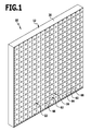
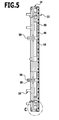
- a luminous display provided overall with the reference numeral 10 is shown. It comprises a housing 12, a carrier 14 in the form of a printed circuit board or printed circuit board and a plurality of luminous elements 16.
- the carrier 14 is first equipped to produce the illuminated display 10 on one side with the light elements 16.
- the light-emitting elements 16 are preferably light-emitting diodes in the form of so-called SMD LEDs. Surface-mounted on a back of the light emitting elements 16 formed terminal contacts can be soldered directly to the carrier 14 in the SMD LEDs. This allows a machine assembly of the carrier 14 with the lighting elements 16.
- Also suitable as light-emitting elements 16 are so-called 3-in-1 LEDs, in which three light-emitting diode elements, so quasi three LEDs are installed in a chip in a small housing.
- lighting elements 16 of any color can be used. It Light elements 16 of different colors or so-called white light LEDs can be used.
- the carrier 14 Before or after the loading of the carrier 14 with the light-emitting elements 16, the carrier 14 is arranged in the housing.
- the carrier 14 is connected to the housing 12 by means of fastening elements 18 in the form of screws or correspondingly formed on the carrier 14 and the housing 12 and cooperating locking elements.
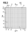
- the housing 12 is formed trough-shaped in the embodiment shown in the figures and has a peripheral edge 20. In a plan view, the housing is square and defines a display side 22. The display side 22 is in FIG. 2 shown in plan view.
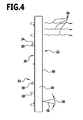
- the carrier 14 is arranged in the housing 12 such that radiation 24 generated by the plurality of luminous elements 16 is emitted in a direction that is perpendicular or substantially perpendicular away from the display side 22.
- connection contacts 30 are led out through corresponding apertures 28, which together form a connection device 32 for connecting the illuminated display 10 to a drive, not shown.
- the connection contacts 30 are sealed in a fluid-tight manner against the housing 12 by means of rubber grommets 34 in order to prevent the penetration of water and moisture into the interior of the housing 12.
- the light-emitting elements 16 may comprise an optical component 36 in the form of a lens, so that light generated by the light-emitting element 16 is radiated at a defined radiation angle 38 relative to a surface normal 40 of a radiation surface 42 of the light-emitting element 16.
- the emitting surface 42 may be quadrangular, that is to say in particular square, or even round.
- the display side 22 associated lighting elements 16 in the case of the embodiment shown in the figures, all, completely covered with a translucent cover 44.
- a potting compound 46 for example, a casting resin based on a polyurethane resin (PUR).
- PUR polyurethane resin
- These are in particular cold and thermosetting two-component casting resins which are solvent-free and therefore prevent attack on solvent-sensitive plastics and odor nuisance by solvents during processing. They are characterized by a good resistance to water, moisture, alkalis, acids and various chemicals.
- the hardened potting compound 46 preferably has an absorption coefficient a v of less than 0.1.
- the potting compound may be partially colored, with a partial coloring a regional coloring or a coloring of different intensity with different colors, such as red, blue, yellow or green to understand.
- the potting compound 46 is also resistant to weathering, so that the fully potted light display 10 in the outdoor area, that can be used outside of closed rooms and outdoors.
- the cover material 44 simultaneously connects the carrier 14 in a fluid-tight manner to the housing 12.
- the potting compound 46 additionally contains a UV protection, so that so-called “substrate chalking" is reliably prevented ,
- the potting compound 46 is crystal clear and highly transparent, that is, it has a very high optical transparency with low optical attenuation.
- the housing 12 After arranging the carrier 14 in the housing 12 remaining cavities are completely filled with the potting compound 46.
- the housing 12 is arranged horizontally and from above, so coming from the display side 22 ago, filled with the liquid potting compound 46.
- the potting compound 46 is distributed uniformly over the carrier 14, so that a distance 48 between an outer surface 50 defined by the hardened potting compound 46 and a luminescent element surface 52 is in a range between 0.5 mm and 8 mm, preferably in a range between 3 mm and 5 mm.
- the outer surface 50 is completely flat.
- a bubble-forming prevention layer 54 can optionally be applied to the optical components 36 and / or the light-emitting elements 16, for example by spraying a clearcoat film having a thickness in one region from 10 ⁇ m to 500 ⁇ m, preferably 100 ⁇ m to 200 ⁇ m.
- the light-emitting elements 16 are arranged on the carrier 14 in rows 56 and columns 58, which run parallel to the edges 20. They define a total matrix 60 of pixels defined by the light elements 16.
- the matrix-shaped arrangement of the lighting elements 16 makes it possible to represent any desired signs and symbols with the illuminated display 10. This is achieved by individual control of the lighting elements 16.
- an antireflection layer 62 can optionally be applied to the outer surface 50, preferably by printing with a matt non-glossy color, so that the antireflection layer 62 has an overall matt surface 64.
- the antireflection layer 62 is not applied to the entire outer surface 50, but only in partial areas. Area regions 66 are recessed which are arranged directly above the luminous elements 16, so that a multiplicity of apertures 68 of the antireflection layer 62 are formed which are preferably formed geometrically similar to the luminous element surfaces 52.
- both the Openings 68 and the luminous element surfaces 52 a square cross-sectional area. This can optionally be round or rectangular.
- the antireflection layer 62 is applied in particular in such a way that dimensions of the apertures 68 are selected such that the entire radiation 24 generated by a direction lobe 70 of the radiation generated by a luminous element 16 can exit through the aperture 68, as shown by way of example in FIG FIG. 7 is shown schematically.
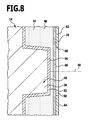
- a matte transparent antireflection layer 74 which completely covers the outer surface 50, be applied directly to the cover material 44, for example by sticking or printing.
- the antireflection layer 74 is preferably formed by a matt clearcoat. This is sufficiently permeable to the radiation 24 generated by the light-emitting elements 16.
- the antireflection layer 62 with the perforations 68 can optionally be dispensed with. To increase the contrast of the illuminated display 10, however, it may also be applied in addition to the antireflection layer 74 on its surface facing away from the luminous elements 16.
- the illuminated display 10 can be used individually or a plurality of units can be interconnected and optionally arranged and installed in other housings, not shown.
- the illuminated display 10 is particularly suitable as an optical display device outside closed rooms or outdoors. It may preferably be used for displaying golfer advertising at sports events.
- the potting compound 46 becomes so on the one hand a risk of injury to persons who come into contact with the light indicator 10, reduced and on the other hand, the protection of the covering compound 46 covered by the light elements 16 and the support 14 increases.
- a pitch 72 of less than 14 mm can be achieved, preferably less than 10 mm.
- the grid dimension 72 is defined by a center distance of two luminous elements 16.
Landscapes
- Physics & Mathematics (AREA)
- General Physics & Mathematics (AREA)
- Engineering & Computer Science (AREA)
- Theoretical Computer Science (AREA)
- Illuminated Signs And Luminous Advertising (AREA)
Applications Claiming Priority (1)
| Application Number | Priority Date | Filing Date | Title |
|---|---|---|---|
| DE102007029213A DE102007029213A1 (de) | 2007-06-13 | 2007-06-13 | Leuchtanzeige und Verfahren zum Herstellen einer Leuchtanzeige |
Publications (2)
| Publication Number | Publication Date |
|---|---|
| EP2003635A2 true EP2003635A2 (fr) | 2008-12-17 |
| EP2003635A3 EP2003635A3 (fr) | 2009-09-02 |
Family
ID=39709056
Family Applications (1)
| Application Number | Title | Priority Date | Filing Date |
|---|---|---|---|
| EP08157951A Withdrawn EP2003635A3 (fr) | 2007-06-13 | 2008-06-10 | Affichage lumineux et procédé de fabrication d'un affichage lumineux |
Country Status (2)
| Country | Link |
|---|---|
| EP (1) | EP2003635A3 (fr) |
| DE (2) | DE102007029213A1 (fr) |
Family Cites Families (10)
| Publication number | Priority date | Publication date | Assignee | Title |
|---|---|---|---|---|
| JPS5850572A (ja) * | 1981-09-22 | 1983-03-25 | 株式会社東芝 | デイスプレイ装置の製造方法 |
| US4890383A (en) * | 1988-01-15 | 1990-01-02 | Simens Corporate Research & Support, Inc. | Method for producing displays and modular components |
| JPH0446381A (ja) * | 1990-06-13 | 1992-02-17 | Tatsuno Co Ltd | 表示装置 |
| BE1007825A5 (fr) * | 1993-12-15 | 1995-10-31 | Niezen Michel | Dispositif lumineux. |
| US20010037591A1 (en) * | 1996-04-15 | 2001-11-08 | Nicholson Timothy J. | Outdoor sign with sealed sign module |
| JPH10116039A (ja) * | 1996-10-11 | 1998-05-06 | T D S Eng:Kk | 発光ダイオードの表示装置 |
| DE19911839A1 (de) * | 1999-03-17 | 2000-10-19 | Leurocom Visuelle Informations | Vorrichtung zur Anzeige von Zeichen und Symbolen |
| CN1464953A (zh) * | 2001-08-09 | 2003-12-31 | 松下电器产业株式会社 | Led照明装置和卡型led照明光源 |
| WO2003017320A1 (fr) * | 2001-08-21 | 2003-02-27 | Nam-Young Kim | Lampe equipee d'une diode electroluminescente |
| DE202004019696U1 (de) * | 2004-12-17 | 2005-05-19 | Rosenbaum, Herbert | Anzeigeelement |
-
2007
- 2007-06-13 DE DE102007029213A patent/DE102007029213A1/de not_active Withdrawn
-
2008
- 2008-06-10 DE DE202008008188U patent/DE202008008188U1/de not_active Expired - Lifetime
- 2008-06-10 EP EP08157951A patent/EP2003635A3/fr not_active Withdrawn
Also Published As
| Publication number | Publication date |
|---|---|
| DE102007029213A1 (de) | 2008-12-18 |
| EP2003635A3 (fr) | 2009-09-02 |
| DE202008008188U1 (de) | 2008-10-02 |
Similar Documents
| Publication | Publication Date | Title |
|---|---|---|
| DE2405829B2 (de) | Elektrolumineszentes halbleiterbauelement und verfahren zu seiner herstellung | |
| DE10303969A1 (de) | Leuchtdiodenträger | |
| EP1081426A2 (fr) | Elément d' éclairage avec une structure porteuse de montage, un couvercle et une source lumineuse | |
| DE10322561A9 (de) | Glaselement mit Lichtrahmen | |
| WO2008043352A2 (fr) | Module optoélectronique et procédé de production d'un module optoélectronique | |
| DE102009008845A1 (de) | Leuchtmodul und Verfahren zum Herstellen eines Leuchtmoduls | |
| EP1371051A2 (fr) | Dispositif d'indication | |
| EP2845233B1 (fr) | Module de del | |
| WO2007115736A1 (fr) | Système de plaque lumineux | |
| DE102010012064A1 (de) | LED-Anordnung mit lichtdurchlässiger Leiterplatte | |
| DE102005057166A1 (de) | Anzeigeelement für ein elektrisches Gerät | |
| EP2404289A1 (fr) | Dispositif d'éclairage comprenant un corps de base en matériau transparent | |
| DE202006005428U1 (de) | Beleuchtbare Fliese | |
| DE202004006389U1 (de) | Beleuchtete Fliese | |
| EP2003635A2 (fr) | Affichage lumineux et procédé de fabrication d'un affichage lumineux | |
| DE102013013985B4 (de) | Leuchtflächenvorrichtung | |
| DE102020201645A1 (de) | Beleuchtungsvorrichtung für ein Kraftfahrzeug | |
| DE10248475B4 (de) | Anzeigevorrichtung | |
| DE10140427B4 (de) | Leuchtenanzeigevorrichtung für den Straßenverkehr | |
| EP0897172A2 (fr) | Dispositif d'affichage pour informations et pour leur utilisation et methode de fabrication | |
| DE10305631B4 (de) | Anzeigevorrichtung | |
| DE102012104580A1 (de) | Flächenhaftes Leuchtobjekt | |
| DE102008007251A1 (de) | Leuchtkörper | |
| DE29518125U1 (de) | Anzeigetafel | |
| DE102005043185A1 (de) | Leuchtvorrichtung |
Legal Events
| Date | Code | Title | Description |
|---|---|---|---|
| PUAI | Public reference made under article 153(3) epc to a published international application that has entered the european phase |
Free format text: ORIGINAL CODE: 0009012 |
|
| AK | Designated contracting states |
Kind code of ref document: A2 Designated state(s): AT BE BG CH CY CZ DE DK EE ES FI FR GB GR HR HU IE IS IT LI LT LU LV MC MT NL NO PL PT RO SE SI SK TR |
|
| AX | Request for extension of the european patent |
Extension state: AL BA MK RS |
|
| PUAL | Search report despatched |
Free format text: ORIGINAL CODE: 0009013 |
|
| AK | Designated contracting states |
Kind code of ref document: A3 Designated state(s): AT BE BG CH CY CZ DE DK EE ES FI FR GB GR HR HU IE IS IT LI LT LU LV MC MT NL NO PL PT RO SE SI SK TR |
|
| AX | Request for extension of the european patent |
Extension state: AL BA MK RS |
|
| 17P | Request for examination filed |
Effective date: 20100226 |
|
| 17Q | First examination report despatched |
Effective date: 20100324 |
|
| AKX | Designation fees paid |
Designated state(s): AT BE BG CH CY CZ DE DK EE ES FI FR GB GR HR HU IE IS IT LI LT LU LV MC MT NL NO PL PT RO SE SI SK TR |
|
| STAA | Information on the status of an ep patent application or granted ep patent |
Free format text: STATUS: THE APPLICATION IS DEEMED TO BE WITHDRAWN |
|
| 18D | Application deemed to be withdrawn |
Effective date: 20100804 |