EP2003714B1 - Bloc-batteries - Google Patents
Bloc-batteries Download PDFInfo
- Publication number
- EP2003714B1 EP2003714B1 EP08251717.8A EP08251717A EP2003714B1 EP 2003714 B1 EP2003714 B1 EP 2003714B1 EP 08251717 A EP08251717 A EP 08251717A EP 2003714 B1 EP2003714 B1 EP 2003714B1
- Authority
- EP
- European Patent Office
- Prior art keywords
- battery
- circuit board
- battery cells
- battery cell
- terminal
- Prior art date
- Legal status (The legal status is an assumption and is not a legal conclusion. Google has not performed a legal analysis and makes no representation as to the accuracy of the status listed.)
- Active
Links
Images















Classifications
-
- H—ELECTRICITY
- H01—ELECTRIC ELEMENTS
- H01M—PROCESSES OR MEANS, e.g. BATTERIES, FOR THE DIRECT CONVERSION OF CHEMICAL ENERGY INTO ELECTRICAL ENERGY
- H01M10/00—Secondary cells; Manufacture thereof
- H01M10/42—Methods or arrangements for servicing or maintenance of secondary cells or secondary half-cells
- H01M10/48—Accumulators combined with arrangements for measuring, testing or indicating the condition of cells, e.g. the level or density of the electrolyte
-
- H—ELECTRICITY
- H01—ELECTRIC ELEMENTS
- H01M—PROCESSES OR MEANS, e.g. BATTERIES, FOR THE DIRECT CONVERSION OF CHEMICAL ENERGY INTO ELECTRICAL ENERGY
- H01M50/00—Constructional details or processes of manufacture of the non-active parts of electrochemical cells other than fuel cells, e.g. hybrid cells
- H01M50/20—Mountings; Secondary casings or frames; Racks, modules or packs; Suspension devices; Shock absorbers; Transport or carrying devices; Holders
- H01M50/204—Racks, modules or packs for multiple batteries or multiple cells
- H01M50/207—Racks, modules or packs for multiple batteries or multiple cells characterised by their shape
- H01M50/213—Racks, modules or packs for multiple batteries or multiple cells characterised by their shape adapted for cells having curved cross-section, e.g. round or elliptic
-
- H—ELECTRICITY
- H01—ELECTRIC ELEMENTS
- H01M—PROCESSES OR MEANS, e.g. BATTERIES, FOR THE DIRECT CONVERSION OF CHEMICAL ENERGY INTO ELECTRICAL ENERGY
- H01M50/00—Constructional details or processes of manufacture of the non-active parts of electrochemical cells other than fuel cells, e.g. hybrid cells
- H01M50/50—Current conducting connections for cells or batteries
- H01M50/528—Fixed electrical connections, i.e. not intended for disconnection
- H01M50/529—Intercell connections through partitions, e.g. in a battery casing
-
- Y—GENERAL TAGGING OF NEW TECHNOLOGICAL DEVELOPMENTS; GENERAL TAGGING OF CROSS-SECTIONAL TECHNOLOGIES SPANNING OVER SEVERAL SECTIONS OF THE IPC; TECHNICAL SUBJECTS COVERED BY FORMER USPC CROSS-REFERENCE ART COLLECTIONS [XRACs] AND DIGESTS
- Y02—TECHNOLOGIES OR APPLICATIONS FOR MITIGATION OR ADAPTATION AGAINST CLIMATE CHANGE
- Y02E—REDUCTION OF GREENHOUSE GAS [GHG] EMISSIONS, RELATED TO ENERGY GENERATION, TRANSMISSION OR DISTRIBUTION
- Y02E60/00—Enabling technologies; Technologies with a potential or indirect contribution to GHG emissions mitigation
- Y02E60/10—Energy storage using batteries
Definitions
- the present invention relates to a battery pack.
- Embodiments of the present invention relate to battery packs with which it is possible to enhance impact resistance performance.
- Embodiments of the present invention still further relate to battery packs which can be improved in impact resistance performance in relation to an impact load generated upon dropping of the battery pack or in the like occasion.
- a battery pack includes a plurality of cylindrical battery cells arranged in a plurality of rows and a plurality of layers, a partition member for partitioning the battery cells from each other, electrode tables for electrical connection between terminals of the battery cells partitioned by the partition member, a lower case for containing the battery cells electrically connected through the electrode tabs, and an upper cover for covering the lower case in which the battery cells are contained, and is detachably attached to a body of an electronic apparatus, to be used as a power source for the electronic apparatus (refer to Patent Document 1).
- a battery pack includes a plurality of cylindrical battery cells, electrode tabs for electrically connecting terminals of the battery cells arranged in a certain pattern, a lower case for containing the battery cells electrically connected through the electrode tabs, and an upper cover for covering the lower case in which the battery cells are contained, and is detachably attached to a body of an electronic apparatus, to be used as a power source for the electronic apparatus (refer to Patent Document 1).
- a battery pack includes a plurality of cylindrical battery cells arranged in a plurality of row and a plurality of layers, a partition member for partitioning the battery cells, electrode tabs for electrically connecting terminals of the battery cells partitioned by the partition member, a lower case for containing therein the battery cells electrically connected through the electrode tabs, and an upper cover for covering the lower case containing the battery cells therein, and is detachably attached to a body of an electronic apparatus, to be used as a power source for the electronic apparatus (refer to Patent Document 1).
- a battery pack includes a plurality of cylindrical battery cell arranged in a plurality of rows and a plurality of layers, a partition member for partitioning the battery cells, electrode tabs for electrically connecting terminals of the battery cells partitioned by the partition member, a main circuit board electrically connected to the battery cells through the electrode tabs, a lower case to which to attach the main circuit board and in which to contain the battery cells, and an upper cover for covering the lower case containing the battery cells therein, and is detachably attached to a body of an electronic apparatus, to be used as a power source for the electronic apparatus (refer to Patent Document 1).
- a battery pack includes a plurality of cylindrical battery cells arranged in a plurality of rows and a plurality of layers, a partition member for partitioning the battery cells, electrode tabs for electrically connecting terminals of the battery cells partitioned by the partition member, a lower case for containing the battery cells electrically connected trough the electrode tabs, and an upper cover for covering the lower case containing the battery case therein, and is detachably attached to a body of an electronic apparatus, to be used as a power source for the electronic apparatus (refer to Patent Document 1).
- Battery packs to be used in electronic apparatuses such as video cameras for private use needs a rated voltage of about 7.2 V.
- a battery cell composed of a cylindrical lithium ion secondary cell for example, has a rated voltage of about 3.6 V.
- four such battery cells are arranged in two rows and two layers, the battery cells in each set of paired battery cells are connected in parallel through a main circuit board, and the two sets of the parallel-connected paired battery cells are sequentially connected in series.
- an impact load generated by the dropping of the battery pack or the like may be concentrated on a fixation part providing electrical connection between the battery cell and the electrode tab, resulting in breakage of the fixation part or the like trouble.
- a battery pack characterized by including: a plurality of cylindrical battery cells arranged in a plurality of rows and a plurality of layers; a lower case for supporting the battery cells; and an upper cover welded to the lower case in the state of covering the battery cells supported by the lower case; wherein the lower case is provided with a first welding projection on the inside of its end part to be welded to the upper cover, and with a first welding recess on the outside of the end part; and the upper cover is provided, on the inside of its end part to be welded to the lower case, with a second welding recess to be engaged with the first welding projection, and is provided, on the outside of the end part, with a second welding projection to be engaged with the first welding recess.
- the end parts of the upper cover and the lower case are opposed to and abutted on each other, and are welded to each other by ultrasonic welding.
- the first terminal part 6a is a positive electrode terminal of the battery pack 1, 100
- the second terminal part 6b is a clock line terminal
- the third terminal part 6c is a data line terminal
- the fourth terminal part 6d is an ID terminal to which an ID resistor is connected
- the fifth terminal part 6e is a negative electrode terminal of the battery pack 1, 100.
- the attaching plate 23 is not limited to the one that positions the display circuit board 60 by engagement of its engaging pieces 27 with the display circuit board 60.
- a configuration may be adopted in which the display circuit board 60 is provided with through-holes, whereas the attaching plate 23 is provided with positioning projections correspondingly to the layout positions of the through-holes, and the display circuit board 60 is positioned by inserting the positioning projections into the through-holes.
- the first to third support plate 24a to 24c are formed in this order along the direction from the positioning plate 22 toward the attaching plate 23.
- the fourth to sixth support plates 24d to 24f are formed in this order along the direction from the positioning plate 22 toward the attaching plate 23.
- the support plates 24 formed on the principal surfaces of the partition plate 21 partition each of the battery cells 8a to 8d partition as one row by the partition plate 21, and partition each of the battery cells 8e to 8h partitioned as the other row by the partition plate 21. More specifically, the first support plate 24a partitions the first battery cell 8a and the second battery cell 8b from each other.
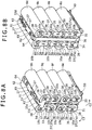
- the first and second battery cells 8a and 8b might be turned in the direction of arrow C1 in FIG. 8A , with the second electrode tab 32 as a center, in such a manner that the positive electrode terminal 10a side of the first and second battery cells 8a and 8b would come off from the partition member 20, resulting in loosening and dropping.
- the fifth and sixth battery cells 8e and 8f might be turned in the direction of arrow C2 in FIG. 8A , with the fourth electrode tab 34 as a center, in such a manner that the negative electrode terminal 10b side of the fifth and sixth battery cells 8e and 8f would come off from the partition member 20, resulting in loosening and dropping.
- the positioning plate 22 since the positioning plate 22 is projected substantially orthogonally to the partition plate 21, the positioning plate 22 may support the first battery cell 8a by clamping it in cooperation with the first projected piece 28a, and may support the fifth battery cell 8e by clamping it in cooperation with the third projected piece 28c. This ensures that the first and second battery cells 8a, 8b and the fifth and sixth battery cells 8e, 8f can be more securely prevented from being loosened and released from the support plates 24.
- the reinforcing ribs 25da to 25de and the reinforcing ribs 25ha to 25he can prevent the attaching plate 23 (which is a part receiving a pressure, particularly) from deformation or the like under the pressure exerted on the attaching plate 23 when the residual charge display switch element 62 mounted on the display circuit board 60 attached to the attaching plate 23 is depressed by the user or the like.
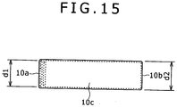
- the inner diameter d3 of the reinforcing rib 25 is greater than the inner diameter d4 by about 0.2 mm, correspondingly to the fact that the outer size d1 on the positive electrode terminal 10a side is greater than the outer size d2 on the negative electrode terminal 10b side by about 0.2 mm.
- FIGS. 8A and 8B the eighth battery cell 8h disposed between the sixth support plate 24f and the attaching plate 23 is so disposed that its positive electrode terminal 10a fronts on the terminal part 6 side, i.e., on the front surface 2b side.
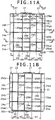
- FIG. 16A is a sectional view taken along line F-F of FIG. 11A
- FIG. 16B is a sectional view taken along line G-G of FIG. 11A .
- the reinforcing ribs 25 are not limited to the curved shapes with the inner diameters d3, d4, insofar as they can support the battery cells 8 without chattering.
- the reinforcing ribs 25 may be formed with the inner diameters set corresponding to the respective outer sizes of the battery cell 8 at the positions where the battery cell 8 is supported by the reinforcing ribs 25.
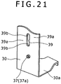
- the slit 39 is formed in the shape of a slot (oblong hole), for example.
- the load absorbing parts 39a, 39a serve to provide electrical connection between the sets of the weld fixation parts 38 at the terminals of the battery cells 8.
- the electrode tab 30 thus provided with the slit 39 and the load absorbing parts 39a, 39a is so provided that, due to the presence of the slit 39, the load absorbing parts 39a, 39a provided at both ends in the width direction of the slit 39 are lower in rigidity than the other parts, particularly, the weld fixation parts 38.
- the impact load generated due to the dropping of the battery pack 1 is concentrated in the load absorbing parts 39a, 39a, so that the electrode tab 30 is plastically or elastically deformed at the load absorbing parts 39a, 39a. Therefore, the load on the electrode tab 30 is concentrated on the load absorbing parts 39a, 39a so provided as to be lower in rigidity than the other parts, whereby the load can be prevented from being concentrated on the weld fixation parts 38 fixing the battery cells 8 and the electrode tab 30, and the load exerted on the weld fixation parts 38 are moderated, whereby the weld fixation parts 38 can be prevented from rupture or the like.
- the electrode tab 30 not provided with any welding slit 201 is provided with a position matching hole 37 for matching the position thereof to the terminal of a battery cell 8 when the electrode tab 30 is spot welded to the terminal of the battery cell 8 by the manufacturer of the battery cell 8.
- the position matching hole 37 is a through-hole which is formed to correspond substantially to the center of the terminal face of the battery cell 8 when the electrode tab 30 is disposed on the terminal of the battery cell 8, and which is formed substantially at the center in the width direction of the electrode tab 30.
- spot welding by use of the first welding electrode and the second welding electrode in the surroundings of the position matching hole 37 is conducted symmetrically on the left and right sides of the position matching hole 37, a total of two times, namely, once on the upper side (in FIG. 18 ) and once on the lower side, whereby the electrode tab 30 is welded to the terminal of the battery cell 8 with four weld fixation parts 38a to 38d.
- the position matching hole 37 and the weld fixation parts 38a to 38d are so laid out that the position matching hole 37 is provided in a central area of the four corners of a substantially rectangular shape defined by the weld fixation parts 38a to 38d; for example, they appear like the spots on a die indicating "5.” Therefore, the manufacturer can easily check, by visual inspection, whether welding has been conducted at all the necessary positions, without leaving any yet-to-be-welded point.
- the tubular projection 37a is formed at the principal surface part, whereby a plurality of electrode tabs 30 can be prevented from being stacked in secure contact with each other, and the manufacturer can be prevented from unknowingly picking up a plurality of electrode tabs 30 at a time.
- the terminal case 40 disposed inside the terminal hole 41 is a roughly rectangular resin part formed to have major edges substantially equal in length with the inside width of the lower case 4.
- the terminal case 40 is provided along its major edge direction with fitting holes 46 in which to contain the joint members 70, and the main circuit board 50 is attached to the terminal case 40.
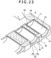
- the joint members 70 are fixed by welding or soldering to the metal-made connection tabs 71 soldered respectively to the terminal connection parts 53a to 53e of the main circuit board 50 attached to the terminal case 40 (see FIG. 25B ). Since the terminal case 40 is disposed inside the lower case 4 together with the main circuit board 50, as shown in FIG. 23 , the joint members 70 are continuous with the support surface parts 44 of the terminal holes 41, and support the terminal pins inserted in the support surface parts 44 in the inserted state.
- the terminal pins are each inserted and held in two component parts, namely, the terminal hole 41 on the lower case 4 side and the terminal case 40 disposed inside the lower case 4. This ensures that, even when a vibration is exerted on the electronic apparatus at the time of loading the battery pack 1, the load exerted on the terminal pins can be lessened, and reliability of electrical connection can be maintained.
- terminal part 6 in the terminal part 6 as above, five terminal parts, namely, the first to fifth terminal parts 6a to 6e are disposed side by side at a lower part of the front surface 2b.
- the first and second terminal parts 6a, 6b and the fourth and fifth terminal parts 6d, 6e are formed at left-right symmetrical positions in the front surface 2b of the casing 2.
- the third terminal part 6c is formed at a position deviated from the center of the front surface 2b toward the side of the fourth and fifth terminal parts 6d, 6e.
- an end face of the insertion guide groove 11 is exposed at the center of the front surface 2b.
- the terminals formed at the terminal parts 6a to 6e have respective functions assigned according to the SMBus interface standard. Specifically, the first terminal part 6a has the function of a positive electrode terminal of the battery pack 1, the second terminal part 6b has the function of a clock line terminal, the third terminal part 6c has the function of a data line terminal, the fourth terminal part 6d has the function of an ID terminal to which an ID resistor is connected, and the fifth terminal part 6e has the function of a negative electrode terminal of the battery pack 1.
- the ID resistance detected through the fourth terminal part 6d is used to detect, on the electronic apparatus side, which one of a plurality of types of battery packs prepared according to the different values of capacity has been loaded; in short, different resistance values are set respectively for the L-size battery pack 1 and the S-size battery pack 100.
- a terminal pin is inserted into the fourth terminal part 6d, the resistance on the side of the battery pack 1, 100 is measured on the electronic apparatus side, and it is decided which one of the battery packs 1 and 100 has been loaded.
- the battery pack 1 has a configuration in which the terminal parts 6a to 6e are disposed at nonuniform intervals, and, accordingly, the terminal pins formed on the battery mount part 5 side are also formed at nonuniform intervals corresponding to the terminal parts 6a to 6e, respectively. Therefore, the terminal pins may not be inserted into the terminal parts 6a to 6e when the left and right sides of the battery pack 1 are reversed (in relation to those in the correct insertion mode), so that mis-insertion of the battery pack 1 into the battery mount part 5 can be obviated.
- the main circuit board 50 is attached to the principal surface, on the opposite side of the principal surface brought into contact with the terminal holes 41, of the terminal case 40.
- the principal surface, on the opposite side of the principal surface brought into contact with the terminal holes 41, of the terminal case 40 is provided with board support parts 47 for clamping one minor edge of the main circuit board 50 in the thickness direction of the main circuit board 50.
- the board support part 47 includes a lower side support part 47a for supporting one principal surface of the main circuit board 50, and an upper side support part 47b for supporting the other principal surface of the main circuit board 50.
- the lower side support parts 47a are projectingly provided in plurality between both end parts in the major edge direction of the terminal case 40 and the fitting holes 46.
- a lower side support part 47c supporting the one-side principal surface of the main circuit board 50 in the same manner as the lower side support part 47a but projected largely as compared with the lower side support part 47a is provided.
- the upper side support parts 47b are projectingly provided near both ends in the width direction of the main circuit board 50, in the state of being spaced from the lower side support parts 47a, 47c by an amount roughly equivalent to the thickness of the main circuit board 50.
- the main circuit board 50 disposed inside the lower case 4 together with the terminal case 40 is mounted while being supported by the board support parts 47, so that the main circuit board 50 is provided in the state of being spaced from the inside bottom surface of the lower case 4. This ensures that electronic parts larger in height than existing ones can also be mounted on the principal surface, facing the bottom surface of the lower case 4, of the main circuit board 50.
- the main circuit board 50 is provided with support protrusion passing holes 55 through which to pass the support protrusions 4b, correspondingly to the layout positions of the support protrusions 4b.
- the support protrusion passing holes 55 are formed to be larger in diameter than the support protrusions 4b, which prevents the main circuit board 50 from interfering with the support protrusions 4b. This ensures that the main circuit board 50 is provided inside the lower case 4 in the state of being supported by the terminal case 40 in a cantilever mode, without interfering with the lower case 4.
- the lower case 4 is welded to the upper cover 3 in the state of covering the battery cell 8 contained therein.
- the upper cover 3 is formed by use of a synthetic resin.
- one side surface 2c which is adjacent to the front surface 2b and the back surface 2e and which is directed vertically up when the battery pack 1 is mounted into the battery mount part 5, of the casing 2 is provided with an identification part 9a for identification of the gripping surfaces according to the mounting direction.
- the front surface 2b and the back surface 2e of the casing 2 are provided with anti-slip parts 9b at the positions of gripping by the user.
- the anti-slip parts 9b formed in the front surface 2b and the back surface 2e are provided for permitting the user to easily grip the casing 2 and for preventing slip-off of the casing 2 at the time of mounting the battery pack 1 into the battery mount part 5, in consideration of the fact that the battery pack 1 for use in business-use electronic apparatuses contains more battery cells 8 and is hence heavier as compared with the battery pack for use in private-use electronic apparatuses.
- the anti-slip parts 9b are formed by forming recessed surface parts at upper parts of the front surface 2b and the back surface 2e, and graining the inside of the recessed surface parts.
- the battery pack 1 permits the user to see that the casing 2 is being gripped correctly for mounting it into the battery mount part 5, to avoid mis-insertion of the battery pack 1, and to securely recognize an increase, if any, in the weight of the casing 2.
- the casing 2 including the lower case 4 and the upper cover 3 has a configuration in which the lower case 4 and the upper cover 3 are greater in material thickness than the partition member 20.
- the casing 2 is set to be thinner and the casing 2 is set to be thicker, it is possible, for example while using the same overall amount of resin material as in the related art, to enhance the strength of the casing 2 and to enhance the impact strength performance.
- the battery pack 1 has a configuration in which the material thickness of the partition member 20 contained in the casing 2 is set smaller, a reduction in the overall size of the casing 2 can be promised.
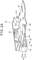
- FIG. 32 is an essential part enlarged view of part J of FIG. 29B and part K of FIG. 30B , showing the condition where end parts of the upper cover 3 and the lower case 4 are opposed to and abutted on each other.
- the lower case 4 is formed with a first welding projection 4c along the whole inside periphery of the end part to be welded to the upper cover 3, and with a first welding recess 4d along the whole outside periphery of the end part.
- the upper cover 3 is formed with a second welding recess 3c to be engaged with the first welding projection 4c, along the whole inside periphery of the end part to be welded to the lower case 4, and with a second welding projection 3d to be engaged with the first welding recess 4d, along the whole outside periphery of the end part.
- the lower case 4 is not limited to the configuration in which the first welding projection 4c and the first welding recess 4d are formed with rough surfaces, and it suffices that either one of the first welding projection 4c and the first welding recess 4d is formed with a rough surface, insofar as ultrasonic welding of the upper cover 3 and the lower case 4 can be achieved easily.
- the configuration in which the first welding projection 4c and/or the first welding recess 4d of the lower case 4 is formed with a rough surface is not limitative, and a configuration may be adopted in which the second welding projection 3d and/or the second welding recess 3c of the upper cover 3 is formed with a rough surface.
- a configuration may be adopted in which the first welding projection 4c and/or the first welding recess 4d and the second welding projection 3d and/or the second welding recess 3c are formed with rough surfaces.
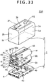
- the S-size battery pack 100 in which four battery cells 8i to 81 are contained in two rows and two layers will be described.
- the parts having configurations the same as or equivalent to those in the L-size battery pack 1 described above will be denoted by the same reference symbols as used above, and descriptions of them will be omitted.
- the third battery cell 8k is disposed in the vicinity of a fifth terminal connection part 53e (see FIG. 25B ) which is electrically connected to a fifth terminal part 6e and which is disposed on the other side in the width direction of the main circuit board 50, and the fourth battery cell 81 is disposed on the third battery cell 8k.
- the battery cells 8 arranged in two rows and two layers as above have to be all (four of them) connected in series, since the battery pack 100 needs a rated voltage of about 14.4 V and each of the battery cells 8 has a rated voltage of about 3.6 V.
- the terminals of the battery cells 8 in the state of being partitioned by a partition member 20 are connected through electrode tabs 80, whereby the four battery cells 8 are connected in series.
- the positive electrode terminal 10a of the third battery cell 8k disposed in the row on the other side and the negative electrode terminal 10b of the fourth battery cell 81 are electrically connected to each other through a fourth electrode tab 84.
- the fourth electrode tab 84 is fixed to the terminals by spot welding, and its tip part 34a is bent and soldered to a fourth electrode terminal connection part 52d of the main circuit board 50.
- the four battery cells 8 arranged in two rows and two layers as above-described, namely, the first battery cell 8i, the second battery cell 8j, the fourth battery cell 81 and the third battery cell 8k in this order are connected in series through the electrode tabs 80.
- the partition member 20 is fitted with a display circuit board 60 on the upper side of the second battery cell 8j and the fourth battery cell 81.
- the display circuit board 60 is electrically connected to a board connection tab part 83a formed at a substantially middle position of the third electrode tab 83.
- the board connection tab part 83a is bent relative to the third electrode tab 83, and is soldered to a board connection part 63 of the display circuit board 60.
- the display circuit board 60 is electrically connected to the main circuit board 50 through a flexible flat cable 36.
- the flexible flat cable 36 is fixed at its one end to a cable connection part 64 of the display circuit board 60, and is electrically connected at its other end to the third electrode tab connection part 52c of the main circuit board 50. This permits the third electrode tab 83 to be electrically connected to the main circuit board 50 through the display circuit board 60, without needing complicated wiring or the like.
- the partition plate 21 has the principal surfaces, each of which the minor edges where the positioning plate 22 and the attaching plate 23 are formed have a length approximately equal to the overall length of the battery cell, and the major edges have a length approximately equal to the overall height of the battery cells 8 stacked in two layers.
- the partition plate 21 having such principal surfaces is disposed between the one-side row of the battery cells 8 arranged in two rows and two layers, specifically, the row including the first and second battery cells 8i, 8j, and the other-side row of the battery cells 8, specifically, the row including the third and fourth battery cells 8k, 81, thereby partitioning the battery cells 8i, 8j in the one-side row from the battery cells 8k, 81 in the other-side row.
- the positioning plate 22, the attaching plate 23 and the display circuit board 60 are configured in the same manner as above-described, and, hence, descriptions of them are omitted.
- the support plate 24 is disposed so as to be substantially parallel to the positioning plate 22 and the attaching plate 23, namely, to be substantially orthogonal to the principal surface of the partition plate 21, and to provide substantially regular intervals (which are approximately equal to the diameter of the battery cell 8) along the major edge direction (height direction) of the partition plate 21.
- the first support plate 24g is formed on the principal surface on one side of the partition plate 21, and the second support plate 24h is formed on the principal surface on the other side of the partition plate 21.
- the first partition plate 24g partitions the first battery cell 8i and the second battery cell 8j from each other.
- the second support plate 24h partitions the third battery cell 8k and the fourth battery cell 81 from each other.
- the first battery cell 8i is disposed between the first support plate 24g and the positioning plate 22
- the second battery cell 8j is disposed between the first support plate 24g and the attaching plate 23
- the third battery cell 8k is disposed between the second support plate 24h and the positioning plate 22
- the fourth battery cell 81 is disposed between the second support plate 24h and the attaching plate 23.
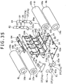
- the first battery cell 8i disposed in the one-side row and the third battery cell 8k disposed in the other-side row are not connected through the first, second, fourth and fifth electrode tabs 81, 82, 84, 85 in the manner of bridging between the one-side row and the other-side row, either on the side of the front surface 2b or on the side of the back surface 2e.
- the negative electrode terminal 10b of the first battery cell 8i and the positive electrode terminal 10a of the second battery cell 8j are connected to each other by the second electrode tab 82 on the back surface 2e side.
- the positive electrode terminal 10a of the third battery cell 8k and the negative electrode terminal 10b of the fourth battery cell 81 are connected to each other by the fourth electrode tab 84 on the back surface 2e side.
- the first battery cell 8i may be turned in the direction of arrow L1 in FIG.
- the third battery cell 8k may be turned in the direction of arrow L2 in FIG. 34A , with the fourth electrode tab 84 as a center, in such a manner that the negative electrode terminal 10b side of the third battery cell 8k would be loosened and released from the partition member 20.
- the first battery 8i and the third battery cell 8k are supported by the support plates 24 so that they would not be loosened and released from the partition member 20.
- the first support plate 24g is provided with a first projected piece (not shown) for supporting the first battery cell 8i
- the second support plate 24h is provided with a second projected piece 28f for supporting the second battery cell 8j (hereinafter, the first projected piece (not shown) and second projected piece 28f will also be referred to simply as the projected pieces 28).
- the first projected piece 28 (not shown) cooperates with the positioning plate 22 adjacent thereto in the height direction in clampingly supporting therebetween the first battery cell 8i disposed between the first projected piece (not shown) and the positioning plate 22.
- the second projected piece 28f cooperates with the positioning plate 22 adjacent thereto in the height direction in clampingly supporting therebetween the third battery cell 8k disposed between the second projected piece 28f and the positioning plate 22.
- the first battery cell 8i is supported by being clamped between the first projected piece (not shown) and the positioning plate 22
- the third battery cell 8k is supported by being clamped between the second projected piece 28f and the positioning plate 22.
- the projected pieces 28 can prevent the first battery cell 8i and the third battery cell 8k (which are not connected by the electrode tabs 80 in the manner of bridging between the one-side row and the other-side row) from being loosened and released from the support plates 24.
- Reinforcing ribs 25, the electrode tabs 80, a lower case 4, and an upper cover 3 are configured in the same manner as in the above-described battery pack 1, and, therefore, descriptions of them are omitted.
- the battery cells 8 each having a rated voltage of about 3.6 V are arranged in two rows and four layers, the battery cells 8 in each set of paired battery cells are connected in parallel, and the four sets of the parallel-connected paired battery cells 8 are sequentially connected in series, whereby a rated voltage of about 14.4 V can be realized, permitting the battery pack 1 to be used in business-use electronic apparatuses.
- the display circuit board 60 is electrically connected to the board connection tab part 33d formed at a substantially middle position of the continuous tab part 33c of the third electrode tab 33, and, further, the display circuit board 60 is electrically connected to the main circuit board 50 through the flexible flat cable 36. Therefore, the third electrode tab 33 can be electrically connected to the main circuit board 50 through the display circuit board 60, without need for complicated wiring or the like.
- the main circuit board 50 is electrically connected through the first to fifth electrode tabs 31 to 35 for electrical connection between the terminals of the battery cells 8. Therefore, respective set voltages of the sets of parallel-connected paired battery cells 8 can be detected by the voltage detection unit 56 in the main circuit board 50, and it is possible to check the residual battery charges of the battery cells 8, the presence/absence of an abnormality in the battery cells 8, etc.
- the battery packs 1, 100 are not limited to the configuration in which the four sets (a total number being eight) of parallel-connected paired battery cells 8 are connected in series or the four battery cells 8 are directly connected in series, for realizing a rated voltage of about 14.4 V which is demanded for business-use electronic apparatuses.
- a configuration may be adopted in which four sets (a total number being twelve) of three-membered grouped battery cells are connected in series to realize a rated voltage of about 14.4 V.
- the application of the battery packs 1, 100 is not limited to the application to the video camera 7 described above, and the battery packs are applicable also to other electronic apparatuses for business use.
- the application of the battery packs 1, 100 is not limited to the application to business-use electronic apparatus described above, and the battery packs are applicable also to private-use electronic apparatuses.
Landscapes
- Chemical & Material Sciences (AREA)
- Chemical Kinetics & Catalysis (AREA)
- Electrochemistry (AREA)
- General Chemical & Material Sciences (AREA)
- Engineering & Computer Science (AREA)
- Manufacturing & Machinery (AREA)
- Battery Mounting, Suspending (AREA)
- Connection Of Batteries Or Terminals (AREA)
Claims (9)
- Système de batterie comprenant :une pluralité de cellules de batterie cylindriques agencées en une pluralité de rangées et une pluralité de couches ;un élément de séparation pour séparer lesdites cellules de batterie ;un boîtier inférieur pour soutenir ledit élément de séparation ;une carte de circuit principale connectée électriquement auxdites cellules de batterie ; etune carte de circuit d'affichage disposée sur le côté opposé de ladite carte de circuit principale ;dans lequel ledit élément de séparation est muni d'une plaque de séparation, d'une plaque de positionnement pour positionner ladite carte de circuit principale, ladite plaque de positionnement étant prévue sur le côté, en regard dudit boîtier inférieur, de ladite plaque de séparation, et d'une plaque de fixation pour fixer ladite carte de circuit d'affichage, ladite plaque de fixation étant prévue sur le côté opposé de ladite plaque de positionnement par rapport à ladite plaque de séparation,dans lequel ledit élément de séparation est réalisé avec des nervures de renforcement dans les coins, réalisées entre ladite plaque de séparation et ladite plaque de fixation.
- Système de batterie selon la revendication 1, dans lequel
ladite carte de circuit d'affichage est pourvue d'un élément de commutation du type bouton-poussoir ; et
lesdites nervures de renforcement sont réalisées avec un intervalle plus petit du côté sur lequel ledit élément de commutation est prévu. - Système de batterie selon la revendication 1, dans lequel ledit élément de séparation est réalisé avec une partie de positionnement et/ou une saillie de positionnement, pour positionner ladite carte de circuit principale.
- Système de batterie selon la revendication 1, dans lequel ladite plaque de fixation est réalisée avec une pièce de contact pour positionner ladite carte de circuit d'affichage et pour soutenir ladite carte de circuit d'affichage dans l'état positionné par contact avec la carte de circuit d'affichage.
- Système de batterie selon la revendication 1, dans lequel ledit élément de séparation est réalisé en utilisant une résine isolante.
- Système de batterie selon la revendication 1, dans lequel ledit élément de séparation est soutenu par une protubérance de support intégrée au boîtier inférieur.
- Système de batterie selon la revendication 1, dans lequel l'épaisseur de matériau dudit boîtier est une épaisseur définie pour que le boîtier soit conforme à la norme UL (acronyme de Underwriters Laboratories Inc.) 94 (ignifugation des matières plastiques).
- Système de batterie selon la revendication 1, dans lequel ledit élément de séparation comprend une résine isolante.
- Système de batterie selon la revendication 1, dans lequel ladite carte de circuit principale est espacée d'une surface inférieure dudit boîtier inférieur.
Applications Claiming Priority (10)
| Application Number | Priority Date | Filing Date | Title |
|---|---|---|---|
| JP2007130877A JP5141090B2 (ja) | 2007-05-16 | 2007-05-16 | バッテリパック |
| JP2007130878A JP5332135B2 (ja) | 2007-05-16 | 2007-05-16 | バッテリパック |
| JP2007130881A JP5162958B2 (ja) | 2007-05-16 | 2007-05-16 | バッテリパック |
| JP2007130884A JP5056155B2 (ja) | 2007-05-16 | 2007-05-16 | バッテリパック |
| JP2007130886A JP5200420B2 (ja) | 2007-05-16 | 2007-05-16 | バッテリパック |
| JP2007130885A JP5205805B2 (ja) | 2007-05-16 | 2007-05-16 | バッテリパック |
| JP2007130879A JP5233162B2 (ja) | 2007-05-16 | 2007-05-16 | バッテリパック |
| JP2007130880A JP5233163B2 (ja) | 2007-05-16 | 2007-05-16 | バッテリパック |
| JP2007130883A JP5119735B2 (ja) | 2007-05-16 | 2007-05-16 | バッテリパック |
| JP2007130882A JP5115696B2 (ja) | 2007-05-16 | 2007-05-16 | バッテリパック |
Publications (3)
| Publication Number | Publication Date |
|---|---|
| EP2003714A2 EP2003714A2 (fr) | 2008-12-17 |
| EP2003714A3 EP2003714A3 (fr) | 2014-05-21 |
| EP2003714B1 true EP2003714B1 (fr) | 2018-10-03 |
Family
ID=39800509
Family Applications (1)
| Application Number | Title | Priority Date | Filing Date |
|---|---|---|---|
| EP08251717.8A Active EP2003714B1 (fr) | 2007-05-16 | 2008-05-15 | Bloc-batteries |
Country Status (1)
| Country | Link |
|---|---|
| EP (1) | EP2003714B1 (fr) |
Families Citing this family (3)
| Publication number | Priority date | Publication date | Assignee | Title |
|---|---|---|---|---|
| DE102007031857A1 (de) * | 2007-07-09 | 2009-01-15 | Robert Bosch Gmbh | Akkumulator |
| JPWO2018135140A1 (ja) | 2017-01-19 | 2019-11-07 | ソニー株式会社 | 複合材料、電子機器および電子機器の製造方法 |
| CN222355395U (zh) * | 2024-01-03 | 2025-01-14 | 浙江极氪智能科技有限公司 | 用于电池的绝缘膜以及电池 |
Family Cites Families (2)
| Publication number | Priority date | Publication date | Assignee | Title |
|---|---|---|---|---|
| JP3932934B2 (ja) | 2002-03-05 | 2007-06-20 | ソニー株式会社 | 二次電池収納ケース |
| JP4123515B2 (ja) * | 2003-12-26 | 2008-07-23 | ソニー株式会社 | バッテリー装置 |
-
2008
- 2008-05-15 EP EP08251717.8A patent/EP2003714B1/fr active Active
Non-Patent Citations (1)
| Title |
|---|
| None * |
Also Published As
| Publication number | Publication date |
|---|---|
| EP2003714A3 (fr) | 2014-05-21 |
| EP2003714A2 (fr) | 2008-12-17 |
Similar Documents
| Publication | Publication Date | Title |
|---|---|---|
| US8080332B2 (en) | Battery pack including cylindrical cells arranged in two rows and two layers | |
| US8614016B2 (en) | Battery pack having enhanced manufacturing efficiency | |
| US8080331B2 (en) | Battery pack including eight cylindrical cells in series-parallel configuration | |
| US8691412B2 (en) | Battery pack | |
| US8647764B2 (en) | Battery pack | |
| US7638234B2 (en) | Battery pack including ultrasonic welding surfaces | |
| US8216714B2 (en) | Battery pack | |
| US9105914B2 (en) | Battery pack including electrode tabs with load absorbing parts | |
| US8597810B2 (en) | Battery pack | |
| US7955727B2 (en) | Battery pack | |
| US8741461B2 (en) | Battery pack having waterproof structure | |
| EP2003714A2 (fr) | Bloc-batteries |
Legal Events
| Date | Code | Title | Description |
|---|---|---|---|
| PUAI | Public reference made under article 153(3) epc to a published international application that has entered the european phase |
Free format text: ORIGINAL CODE: 0009012 |
|
| 17P | Request for examination filed |
Effective date: 20080528 |
|
| AK | Designated contracting states |
Kind code of ref document: A2 Designated state(s): AT BE BG CH CY CZ DE DK EE ES FI FR GB GR HR HU IE IS IT LI LT LU LV MC MT NL NO PL PT RO SE SI SK TR |
|
| AX | Request for extension of the european patent |
Extension state: AL BA MK RS |
|
| PUAL | Search report despatched |
Free format text: ORIGINAL CODE: 0009013 |
|
| AK | Designated contracting states |
Kind code of ref document: A3 Designated state(s): AT BE BG CH CY CZ DE DK EE ES FI FR GB GR HR HU IE IS IT LI LT LU LV MC MT NL NO PL PT RO SE SI SK TR |
|
| AX | Request for extension of the european patent |
Extension state: AL BA MK RS |
|
| RIC1 | Information provided on ipc code assigned before grant |
Ipc: H01M 2/00 20060101AFI20140414BHEP |
|
| 17Q | First examination report despatched |
Effective date: 20140506 |
|
| AKX | Designation fees paid |
Designated state(s): DE FR GB |
|
| AXX | Extension fees paid |
Extension state: MK Extension state: RS Extension state: BA Extension state: AL |
|
| STAA | Information on the status of an ep patent application or granted ep patent |
Free format text: STATUS: EXAMINATION IS IN PROGRESS |
|
| GRAP | Despatch of communication of intention to grant a patent |
Free format text: ORIGINAL CODE: EPIDOSNIGR1 |
|
| STAA | Information on the status of an ep patent application or granted ep patent |
Free format text: STATUS: GRANT OF PATENT IS INTENDED |
|
| INTG | Intention to grant announced |
Effective date: 20180413 |
|
| GRAS | Grant fee paid |
Free format text: ORIGINAL CODE: EPIDOSNIGR3 |
|
| GRAA | (expected) grant |
Free format text: ORIGINAL CODE: 0009210 |
|
| STAA | Information on the status of an ep patent application or granted ep patent |
Free format text: STATUS: THE PATENT HAS BEEN GRANTED |
|
| AK | Designated contracting states |
Kind code of ref document: B1 Designated state(s): DE FR GB |
|
| REG | Reference to a national code |
Ref country code: GB Ref legal event code: FG4D |
|
| REG | Reference to a national code |
Ref country code: DE Ref legal event code: R096 Ref document number: 602008057214 Country of ref document: DE |
|
| REG | Reference to a national code |
Ref country code: DE Ref legal event code: R097 Ref document number: 602008057214 Country of ref document: DE |
|
| PLBE | No opposition filed within time limit |
Free format text: ORIGINAL CODE: 0009261 |
|
| STAA | Information on the status of an ep patent application or granted ep patent |
Free format text: STATUS: NO OPPOSITION FILED WITHIN TIME LIMIT |
|
| 26N | No opposition filed |
Effective date: 20190704 |
|
| REG | Reference to a national code |
Ref country code: DE Ref legal event code: R079 Ref document number: 602008057214 Country of ref document: DE Free format text: PREVIOUS MAIN CLASS: H01M0002000000 Ipc: H01M0050000000 |
|
| P01 | Opt-out of the competence of the unified patent court (upc) registered |
Effective date: 20230527 |
|
| PGFP | Annual fee paid to national office [announced via postgrant information from national office to epo] |
Ref country code: DE Payment date: 20250423 Year of fee payment: 18 |
|
| PGFP | Annual fee paid to national office [announced via postgrant information from national office to epo] |
Ref country code: FR Payment date: 20250424 Year of fee payment: 18 |
|
| PGFP | Annual fee paid to national office [announced via postgrant information from national office to epo] |
Ref country code: GB Payment date: 20260317 Year of fee payment: 19 |