EP2003733B1 - Elektrische Anschlussklemme und eine solche Klemme umfassendes elektrisches Schutzgerät - Google Patents
Elektrische Anschlussklemme und eine solche Klemme umfassendes elektrisches Schutzgerät Download PDFInfo
- Publication number
- EP2003733B1 EP2003733B1 EP08354022A EP08354022A EP2003733B1 EP 2003733 B1 EP2003733 B1 EP 2003733B1 EP 08354022 A EP08354022 A EP 08354022A EP 08354022 A EP08354022 A EP 08354022A EP 2003733 B1 EP2003733 B1 EP 2003733B1
- Authority
- EP
- European Patent Office
- Prior art keywords
- flap
- called
- connection terminal
- terminal
- tunnel
- Prior art date
- Legal status (The legal status is an assumption and is not a legal conclusion. Google has not performed a legal analysis and makes no representation as to the accuracy of the status listed.)
- Active
Links
Images


Classifications
-
- H—ELECTRICITY
- H01—ELECTRIC ELEMENTS
- H01R—ELECTRICALLY-CONDUCTIVE CONNECTIONS; STRUCTURAL ASSOCIATIONS OF A PLURALITY OF MUTUALLY-INSULATED ELECTRICAL CONNECTING ELEMENTS; COUPLING DEVICES; CURRENT COLLECTORS
- H01R4/00—Electrically-conductive connections between two or more conductive members in direct contact, i.e. touching one another; Means for effecting or maintaining such contact; Electrically-conductive connections having two or more spaced connecting locations for conductors and using contact members penetrating insulation
- H01R4/28—Clamped connections, spring connections
- H01R4/30—Clamped connections, spring connections utilising a screw or nut clamping member
- H01R4/36—Conductive members located under tip of screw
-
- H—ELECTRICITY
- H01—ELECTRIC ELEMENTS
- H01R—ELECTRICALLY-CONDUCTIVE CONNECTIONS; STRUCTURAL ASSOCIATIONS OF A PLURALITY OF MUTUALLY-INSULATED ELECTRICAL CONNECTING ELEMENTS; COUPLING DEVICES; CURRENT COLLECTORS
- H01R4/00—Electrically-conductive connections between two or more conductive members in direct contact, i.e. touching one another; Means for effecting or maintaining such contact; Electrically-conductive connections having two or more spaced connecting locations for conductors and using contact members penetrating insulation
- H01R4/70—Insulation of connections
-
- H—ELECTRICITY
- H01—ELECTRIC ELEMENTS
- H01R—ELECTRICALLY-CONDUCTIVE CONNECTIONS; STRUCTURAL ASSOCIATIONS OF A PLURALITY OF MUTUALLY-INSULATED ELECTRICAL CONNECTING ELEMENTS; COUPLING DEVICES; CURRENT COLLECTORS
- H01R13/00—Details of coupling devices of the kinds covered by groups H01R12/70 or H01R24/00 - H01R33/00
- H01R13/44—Means for preventing access to live contacts
-
- H—ELECTRICITY
- H01—ELECTRIC ELEMENTS
- H01R—ELECTRICALLY-CONDUCTIVE CONNECTIONS; STRUCTURAL ASSOCIATIONS OF A PLURALITY OF MUTUALLY-INSULATED ELECTRICAL CONNECTING ELEMENTS; COUPLING DEVICES; CURRENT COLLECTORS
- H01R13/00—Details of coupling devices of the kinds covered by groups H01R12/70 or H01R24/00 - H01R33/00
- H01R13/64—Means for preventing incorrect coupling
Definitions
- the present invention relates to a terminal for connecting conductors to a modular electrical appliance housed in an insulating housing, said terminal comprising a cage forming a frame delimiting an opening for inserting a connection pad of the electrical appliance and for a conductor to be connected, a clamping screw for clamping the cable between the connection pad and either the cage or said screw, and a so-called first bib adapted to prevent the insertion of a cable under the cage of the terminal .
- this device comprises a flap consisting of an angled piece integral with the cage and extending in a direction opposite to the screw, so as to prevent access for a cable or the tooth of 'a comb, to the space under the cage. But when the terminal is tightened on a small diameter conductor, if the flap is metallic, there is a risk of electrocution because the flap is accessible.
- the document is known WO 02/075889 describing an electrical apparatus having terminals of the kind previously mentioned, said terminals being equipped with a plastic flap mounted on a bracket, the assembly being fixed to the cage by means of a pin system.
- a plastic flap mounted on a bracket the assembly being fixed to the cage by means of a pin system.
- This terminal comprises a cage having a hook on which can be fixed an insulating part, said insulating part having a wall opposite the opening of the terminal.
- the insulating part has two wings adapted to cooperate with recesses formed in the lower part of the cage for fixing said insulating part on the cage.
- the present invention solves these disadvantages and provides a connection terminal of simple design whose flap is captive and does not increase the size of the terminal.
- the present invention relates to a terminal according to claim 1.
- the vertical locking means comprise a lug provided on the said second bar adapted to cooperate with a notch belonging to the so-called first bar.
- the aforementioned pin is placed inside the so-called second insulating flap on one of the lateral edges of said flap and the notch is placed on one of the lateral edges of the so-called first flap.
- the horizontal locking means of said second flap comprises a clip placed in one of the corners of an elastic face belonging to the so-called second flap, said clips cooperating with said first flap for horizontal locking of the so-called second bib with respect to the so-called first bib.
- the so-called second bib comprises a rear face and a front face, the rear face being connected laterally to the front face by a side wall, and the rear face bearing on the so-called first bib.
- the aforementioned lateral wall comprises the aforementioned pin.
- said second bib comprises a rear face and a front face, said faces being connected to their lower parts by a bottom wall.
- the present invention also relates to an electrical protection device comprising at least one terminal, said terminal having the above-mentioned characteristics taken alone or in combination.
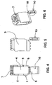
- terminal 1 cage intended to be integrated in the housing 2 of an electrical protection apparatus as shown partially on the figure 7 to make the electrical connection upstream or downstream of said apparatus.
- this terminal comprises a cage 3 consisting of a metal part of substantially parallelepipedal shape having a through opening 4 for allowing the passage of an electrical conductor and the contact area of the device (not shown ).
- This substantially parallelepiped-shaped piece has two side walls 5, 6 connected at their upper part by an upper wall 7 and at their lower part by a bottom wall 8.
- this terminal also comprises a clamping screw (not shown) intended to be screwed into the upper wall 7 of the cage and intended to move or move the cage (according to the chosen embodiment) so as to achieve the tightening of the conductor between the cage and the beach or between the screw and the beach, when it is actuated.
- This terminal also comprises a metal flap 9 said first, integral with said bottom wall 8 and extending substantially perpendicular to said wall 8.
- This flap 9 is intended to prevent the introduction of a driver or a tooth comb by mistake, under the cage 3 of the terminal.
- this terminal also comprises a flap 10, said second, made of an insulating material such as plastic to be fixed on the metal flap 9 as will be explained below.
- This insulating flap 10 is formed by a U-shaped part comprising two main walls 11,12 connected by a bottom wall 13 and laterally by a side wall 14. This part is intended to be mounted laterally around the metal flap 9 next the direction of the arrow on the figure 1 .
- This insulating flap 10 comprises, located between its two main faces 11, 12, fixed on the aforementioned side face 14, on one of the lateral edges of the insulating flap 10 and halfway up the insulating flap, a lug 15 intended to fit in a notch 16 provided on one 17 of the sides of the metal flap 9 to ensure the locking of the flap insulating in the vertical direction parallel to the axis of movement of the screw or cage as appropriate.
- a lug 15 intended to fit in a notch 16 provided on one 17 of the sides of the metal flap 9 to ensure the locking of the flap insulating in the vertical direction parallel to the axis of movement of the screw or cage as appropriate.
- the lateral size of the terminal is not modified by the insulating flap.
- the bib does not overflow the terminal.
- the costs of the terminal and the insulating flap can remain low.
- the metal bib of the terminal and the insulating flap have simple shapes that can produce low cost manufacturing tools.
- This insulating flap also comprises a clip 18 placed in the angle of one of its main faces 11, 12, this clip 18 being intended to cooperate with the edge 21 of the metal flap 9 opposite that with the notch 16. , so as to lock the insulating flap 10 laterally.
- the face on which the clip is placed is flexible to allow the clips to work. Again, by placing the clip in the corner, the drawers of the mold are achievable while the room is very narrow. Thus, the bib is securely fixed horizontally.
- the lateral size of the terminal is not modified by the insulating flap.
- the bib does not overflow the terminal. Again, the cost of the terminal and the flap remain low.
- the metal bib of the terminal and the insulating flap have simple shapes that can produce low cost manufacturing tools.
- One 11 of the main faces 11, 12 of the insulating flap 10, called the rear face bears behind the metal flap 9 of the terminal, this face being bonded laterally to the other main face 12, said front face by the side wall. aforementioned 14.
- the flap can resist tearing in the outgoing direction of the cable.
- the support of the insulating flap on the rear face of the metal flap and the lateral connection between the rear face and the front face gives strength to the front face of the insulating flap.
- the flap is securely fixed transversely.
- the lateral dimensions of the terminal are not modified by the insulating flap, which does not extend beyond the terminal. The flap thus becomes captive during the assembly of the terminal in the devices thanks to the presence of the two lugs.
- the invention has made it possible to attach an insulating flap on a thin sheet which is demoldable and solid on tearing.
- This invention can be applied to the terminals of circuit breakers and associated equipment, modular or not, advantageously to small caliber devices equipped with small terminals using thin sheets. Its use could also be extended to larger size terminals.
Landscapes
- Connections Arranged To Contact A Plurality Of Conductors (AREA)
- Breakers (AREA)
- Coupling Device And Connection With Printed Circuit (AREA)
- Emergency Protection Circuit Devices (AREA)
Claims (9)
- Klemme zum Anschluss von Leitern an ein, in einem Isolierstoffgehäuse angeordnetes modulares elektrisches Schaltgerät, welche Klemme- einen rahmenförmigen Käfig, in dem eine Öffnung zur Einführung eines Anschlussstücks des elektrischen Schaltgeräts sowie eines anzuschließenden elektrischen Leiters ausgebildet ist,- eine in eine der Wände des Käfigs eingedrehte Klemmschraube zum Festklemmen des Kabels zwischen dem Anschlussstück einerseits und entweder dem Käfig oder der genannten Schraube andererseits durch Verschieben der Schraube oder des Käfigs,- einen so genannten ersten Untersteckschutz, der das Einstecken eines Kabels unter den Käfig der Klemme verhindert,- sowie einen so genannten zweiten Untersteckschutz umfasst, wobei die Klemme Verriegelungsmittel (15, 16) zur Fixierung des so genannten zweiten Untersteckschutzes (10) in Bezug zum so genannten ersten Untersteckschutz (9), in senkrechter Richtung parallel zur Verschiebeachse der Schraube bzw. des Käfigs umfasst, dadurch gekennzeichnet, dass der so genannte zweite Untersteckschutz (10) aus Isolierstoff besteht und in einer annähernd rechtwinklig zur genannten Verschiebeachse verlaufenden Achse seitlich auf dem erwähnten, so genannten ersten Untersteckschutz (9) montiert werden kann, und dass die Klemme Verriegelungsmittel (18) zur Fixierung des so genannten zweiten Untersteckschutzes (10) in Bezug zum so genannten ersten Untersteckschutz (9), in horizontaler Richtung, d.h. annähernd rechtwinklig zur genannten Verschiebeachse umfasst.
- Anschlussklemme nach Anspruch 1, dadurch gekennzeichnet, dass die Vertikalverriegelungsmittel (15,16) einen am so genannten zweiten Untersteckschutz (10) ausgebildeten Vorsprung (15) umfassen, der mit einer im so genannten ersten Untersteckschutz (9) ausgebildeten seitlichen Aussparung (16) zusammenwirkt.
- Anschlussklemme nach Anspruch 1 oder 2, dadurch gekennzeichnet, dass der genannte Vorsprung (15) auf der Innenseite des Isolierstoff-Untersteckschutzes (10), an einem (20) der Seitenränder des genannten Untersteckschutz (10) ausgebildet ist und dass die Aussparung (16) an einem (17) der Seitenränder des so genannten ersten Untersteckschutzes (9) ausgebildet ist.
- Anschlussklemme nach irgendeinem der Ansprüche 1 bis 3, dadurch gekennzeichnet, dass die Verriegelungsmittel zur horizontalen Verriegelung des so genannten zweiten Untersteckschutzes (10) eine, in einer der Ecken einer biegsamen Wand (12) des so genannten zweiten Untersteckschutzes (10) ausgebildete Klammer (18) umfassen, welche genannte Klammer (18) mit dem so genannten ersten Untersteckschutz (9) zusammenwirkt, um die horizontale Verriegelung des so genannten zweiten Untersteckschutzes (10) in Bezug zum so genannten ersten Untersteckschutz (9) zu gewährleisten.
- Anschlussklemme nach Anspruch 4, dadurch gekennzeichnet, dass der so genannte zweite Untersteckschutz (10) eine hintere Wand (11) und eine vordere Wand (12) umfasst, wobei die hintere Wand (11) über eine Seitenwand (14) seitlich mit der vorderen Wand verbunden ist und sich die hintere Wand (11) am so genannten ersten Untersteckschutz (9) abstützt.
- Anschlussklemme nach Anspruch 5, dadurch gekennzeichnet, dass der genannte Vorsprung (15) in der genannten Seitenwand (14) ausgebildet ist.
- Anschlussklemme nach irgendeinem der vorhergehenden Ansprüche, dadurch gekennzeichnet, dass der so genannte zweite Untersteckschutz (10) eine hintere Wand (11) und eine vordere Wand (12) umfasst, welche hintere und vordere Wand an ihrer Unterseite über eine Bodenwand (13) miteinander verbunden sind.
- Elektrisches Schaltgerät mit mindestens einer Klemme nach irgendeinem der vorhergehenden Ansprüche.
- Elektrisches Schaltgerät nach Anspruch 8, dadurch gekennzeichnet, dass es sich um einen Leistungsschalter handelt.
Applications Claiming Priority (1)
| Application Number | Priority Date | Filing Date | Title |
|---|---|---|---|
| FR0704132A FR2917243B1 (fr) | 2007-06-11 | 2007-06-11 | Borne de raccordement electrique et appareil de protection electrique comportant une telle borne |
Publications (2)
| Publication Number | Publication Date |
|---|---|
| EP2003733A1 EP2003733A1 (de) | 2008-12-17 |
| EP2003733B1 true EP2003733B1 (de) | 2009-09-16 |
Family
ID=38902682
Family Applications (1)
| Application Number | Title | Priority Date | Filing Date |
|---|---|---|---|
| EP08354022A Active EP2003733B1 (de) | 2007-06-11 | 2008-03-18 | Elektrische Anschlussklemme und eine solche Klemme umfassendes elektrisches Schutzgerät |
Country Status (6)
| Country | Link |
|---|---|
| EP (1) | EP2003733B1 (de) |
| CN (1) | CN101325287B (de) |
| AT (1) | ATE443354T1 (de) |
| DE (1) | DE602008000142D1 (de) |
| ES (1) | ES2330811T3 (de) |
| FR (1) | FR2917243B1 (de) |
Families Citing this family (3)
| Publication number | Priority date | Publication date | Assignee | Title |
|---|---|---|---|---|
| CN103177909B (zh) * | 2011-12-26 | 2016-03-30 | 西门子公司 | 接线装置 |
| CN102780102A (zh) * | 2012-07-26 | 2012-11-14 | 上海友邦电气(集团)股份有限公司 | 一种用于低压电器的压线框 |
| FR3090225B1 (fr) * | 2018-12-13 | 2020-11-27 | Schneider Electric Ind Sas | Borne a compensation de serrage en particulier pour un appareil de protection electrique. |
Family Cites Families (6)
| Publication number | Priority date | Publication date | Assignee | Title |
|---|---|---|---|---|
| CH456714A (de) * | 1967-11-13 | 1968-07-31 | Oskar Woertz H & O Woe | Elektrische Klemme |
| FR2612340B1 (fr) | 1987-03-13 | 1993-02-12 | Merlin Gerin | Borne de raccordement multiple pour appareil electrique modulaire |
| IT1264956B1 (it) * | 1993-07-20 | 1996-10-17 | Bticino Spa | Apparecchiatura elettrica modulare con protezione intrinseca a prova di dito di morsetti di serraggio |
| FR2720862B1 (fr) * | 1994-06-06 | 1996-07-05 | Schneider Electric Sa | Borne de raccordement pour un appareillage électrique. |
| IT237508Y1 (it) | 1997-05-20 | 2000-09-13 | Gewiss Spa | Struttura di morsetto con protezione a prova di dito,particolarmenteper apparecchiature elettriche |
| AT410613B (de) * | 2001-03-20 | 2003-06-25 | Moeller Gebaeudeautomation Kg | Liftklemme |
-
2007
- 2007-06-11 FR FR0704132A patent/FR2917243B1/fr not_active Expired - Fee Related
-
2008
- 2008-03-18 EP EP08354022A patent/EP2003733B1/de active Active
- 2008-03-18 ES ES08354022T patent/ES2330811T3/es active Active
- 2008-03-18 AT AT08354022T patent/ATE443354T1/de not_active IP Right Cessation
- 2008-03-18 DE DE602008000142T patent/DE602008000142D1/de active Active
- 2008-05-19 CN CN2008100971452A patent/CN101325287B/zh active Active
Also Published As
| Publication number | Publication date |
|---|---|
| ATE443354T1 (de) | 2009-10-15 |
| ES2330811T3 (es) | 2009-12-15 |
| FR2917243B1 (fr) | 2009-07-10 |
| FR2917243A1 (fr) | 2008-12-12 |
| CN101325287B (zh) | 2012-09-05 |
| CN101325287A (zh) | 2008-12-17 |
| EP2003733A1 (de) | 2008-12-17 |
| DE602008000142D1 (de) | 2009-10-29 |
Similar Documents
| Publication | Publication Date | Title |
|---|---|---|
| EP2409553B1 (de) | Steuerbaugruppe mit einem antrieb variabler geschwindigkeit und einem unterbrecherschalter | |
| EP3323171B1 (de) | Isolator für eine schwenkbare elektrische verbindung | |
| EP2891178B1 (de) | Körper zum pressen eines teils auf eine oberfläche | |
| EP2003733A1 (de) | Elektrische Anschlussklemme und eine solche Klemme umfassendes elektrisches Schutzgerät | |
| EP3206259B1 (de) | Elektroschaltgerät mit einer druckverbindungsklemme, die in einem gehäuse aus zwei teilen montiert ist, die nach der einschubrichtung eines elektrischen leiters in die verbindungsklemme zusammengebaut sind | |
| EP1912287B1 (de) | Elektrischer Anschluss für Karte mit gedruckter Schaltung und dichtes elektrisches Gehäuse, das einen solchen Anschluss enthält | |
| EP0785606B1 (de) | Vorrichtung zum Befestigen eines elektrischen Gerätes | |
| EP0683498A1 (de) | Modulares elektrisches Gerät mit Anschlussklemmen geschützt durch eine isolierende Platte | |
| EP0908915B1 (de) | Gehäuse für ein elektrisches Gerät, wie ein Lastschalter | |
| EP2164141B1 (de) | Klemmbacke für elektrischen Anschluss | |
| FR2936656A1 (fr) | Borne de connexion electrique automatique | |
| EP3667824B1 (de) | Klemme mit klemmkompensation, insbesondere für eine elektrische schutzvorrichtung | |
| EP2539722B1 (de) | Gehäuse mit mitteln zum befestigen auf einer trägerplatte | |
| FR2749708A1 (fr) | Borne d'arrivee pour barre d'alimentation en forme de peigne notamment pour appareils electriques modulaires | |
| FR2928784A1 (fr) | Dispositif de raccordement electrique notamment pour panneau solaire electrique | |
| EP3109952B1 (de) | Behälter für einen multigeräteblock, und entsprechender multigeräteblock | |
| WO2024052368A1 (fr) | Goupille | |
| EP3788661A1 (de) | Vorrichtung zum befestigen einer 12v-batterie an einem batteriehalter und kraftfahrzeug mit einer solchen vorrichtung | |
| FR2901068A1 (fr) | Panneau support d'appareillage electrique | |
| FR2747231A1 (fr) | Appareil electrique du type comportant un contacteur presentant un logement pour la mise en place d'un module de protection et un module de protection | |
| FR2537789A1 (fr) | Capuchon-outil pour contact autodenudant | |
| FR3083650A1 (fr) | Dispositif de couplage multipositions d’un faisceau electrique a un jeu de barre(s) conductrice(s) electriquement | |
| FR2759496A1 (fr) | Dispositif de maintien et de realisation de contact d'une pile | |
| BE398676A (de) | ||
| FR2965676A1 (fr) | Coffret de branchement electrique a traverse configurable. |
Legal Events
| Date | Code | Title | Description |
|---|---|---|---|
| PUAI | Public reference made under article 153(3) epc to a published international application that has entered the european phase |
Free format text: ORIGINAL CODE: 0009012 |
|
| AK | Designated contracting states |
Kind code of ref document: A1 Designated state(s): AT BE BG CH CY CZ DE DK EE ES FI FR GB GR HR HU IE IS IT LI LT LU LV MC MT NL NO PL PT RO SE SI SK TR |
|
| AX | Request for extension of the european patent |
Extension state: AL BA MK RS |
|
| 17P | Request for examination filed |
Effective date: 20090115 |
|
| GRAP | Despatch of communication of intention to grant a patent |
Free format text: ORIGINAL CODE: EPIDOSNIGR1 |
|
| RAP1 | Party data changed (applicant data changed or rights of an application transferred) |
Owner name: SCHNEIDER ELECTRIC INDUSTRIES SAS |
|
| RIN1 | Information on inventor provided before grant (corrected) |
Inventor name: VANZETTO, DANIEL |
|
| GRAS | Grant fee paid |
Free format text: ORIGINAL CODE: EPIDOSNIGR3 |
|
| GRAA | (expected) grant |
Free format text: ORIGINAL CODE: 0009210 |
|
| AKX | Designation fees paid |
Designated state(s): AT BE BG CH CY CZ DE DK EE ES FI FR GB GR HR HU IE IS IT LI LT LU LV MC MT NL NO PL PT RO SE SI SK TR |
|
| AK | Designated contracting states |
Kind code of ref document: B1 Designated state(s): AT BE BG CH CY CZ DE DK EE ES FI FR GB GR HR HU IE IS IT LI LT LU LV MC MT NL NO PL PT RO SE SI SK TR |
|
| REG | Reference to a national code |
Ref country code: GB Ref legal event code: FG4D Free format text: NOT ENGLISH |
|
| REG | Reference to a national code |
Ref country code: CH Ref legal event code: EP |
|
| REG | Reference to a national code |
Ref country code: IE Ref legal event code: FG4D |
|
| REF | Corresponds to: |
Ref document number: 602008000142 Country of ref document: DE Date of ref document: 20091029 Kind code of ref document: P |
|
| REG | Reference to a national code |
Ref country code: ES Ref legal event code: FG2A Ref document number: 2330811 Country of ref document: ES Kind code of ref document: T3 |
|
| PG25 | Lapsed in a contracting state [announced via postgrant information from national office to epo] |
Ref country code: SE Free format text: LAPSE BECAUSE OF FAILURE TO SUBMIT A TRANSLATION OF THE DESCRIPTION OR TO PAY THE FEE WITHIN THE PRESCRIBED TIME-LIMIT Effective date: 20090916 Ref country code: NO Free format text: LAPSE BECAUSE OF FAILURE TO SUBMIT A TRANSLATION OF THE DESCRIPTION OR TO PAY THE FEE WITHIN THE PRESCRIBED TIME-LIMIT Effective date: 20091216 Ref country code: LT Free format text: LAPSE BECAUSE OF FAILURE TO SUBMIT A TRANSLATION OF THE DESCRIPTION OR TO PAY THE FEE WITHIN THE PRESCRIBED TIME-LIMIT Effective date: 20090916 Ref country code: FI Free format text: LAPSE BECAUSE OF FAILURE TO SUBMIT A TRANSLATION OF THE DESCRIPTION OR TO PAY THE FEE WITHIN THE PRESCRIBED TIME-LIMIT Effective date: 20090916 |
|
| LTIE | Lt: invalidation of european patent or patent extension |
Effective date: 20090916 |
|
| PG25 | Lapsed in a contracting state [announced via postgrant information from national office to epo] |
Ref country code: HR Free format text: LAPSE BECAUSE OF FAILURE TO SUBMIT A TRANSLATION OF THE DESCRIPTION OR TO PAY THE FEE WITHIN THE PRESCRIBED TIME-LIMIT Effective date: 20090916 Ref country code: PL Free format text: LAPSE BECAUSE OF FAILURE TO SUBMIT A TRANSLATION OF THE DESCRIPTION OR TO PAY THE FEE WITHIN THE PRESCRIBED TIME-LIMIT Effective date: 20090916 Ref country code: LV Free format text: LAPSE BECAUSE OF FAILURE TO SUBMIT A TRANSLATION OF THE DESCRIPTION OR TO PAY THE FEE WITHIN THE PRESCRIBED TIME-LIMIT Effective date: 20090916 Ref country code: NL Free format text: LAPSE BECAUSE OF FAILURE TO SUBMIT A TRANSLATION OF THE DESCRIPTION OR TO PAY THE FEE WITHIN THE PRESCRIBED TIME-LIMIT Effective date: 20090916 Ref country code: SI Free format text: LAPSE BECAUSE OF FAILURE TO SUBMIT A TRANSLATION OF THE DESCRIPTION OR TO PAY THE FEE WITHIN THE PRESCRIBED TIME-LIMIT Effective date: 20090916 |
|
| NLV1 | Nl: lapsed or annulled due to failure to fulfill the requirements of art. 29p and 29m of the patents act | ||
| PG25 | Lapsed in a contracting state [announced via postgrant information from national office to epo] |
Ref country code: CY Free format text: LAPSE BECAUSE OF FAILURE TO SUBMIT A TRANSLATION OF THE DESCRIPTION OR TO PAY THE FEE WITHIN THE PRESCRIBED TIME-LIMIT Effective date: 20090916 |
|
| REG | Reference to a national code |
Ref country code: IE Ref legal event code: FD4D |
|
| PG25 | Lapsed in a contracting state [announced via postgrant information from national office to epo] |
Ref country code: IE Free format text: LAPSE BECAUSE OF FAILURE TO SUBMIT A TRANSLATION OF THE DESCRIPTION OR TO PAY THE FEE WITHIN THE PRESCRIBED TIME-LIMIT Effective date: 20090916 Ref country code: CZ Free format text: LAPSE BECAUSE OF FAILURE TO SUBMIT A TRANSLATION OF THE DESCRIPTION OR TO PAY THE FEE WITHIN THE PRESCRIBED TIME-LIMIT Effective date: 20090916 Ref country code: EE Free format text: LAPSE BECAUSE OF FAILURE TO SUBMIT A TRANSLATION OF THE DESCRIPTION OR TO PAY THE FEE WITHIN THE PRESCRIBED TIME-LIMIT Effective date: 20090916 Ref country code: IS Free format text: LAPSE BECAUSE OF FAILURE TO SUBMIT A TRANSLATION OF THE DESCRIPTION OR TO PAY THE FEE WITHIN THE PRESCRIBED TIME-LIMIT Effective date: 20100116 Ref country code: RO Free format text: LAPSE BECAUSE OF FAILURE TO SUBMIT A TRANSLATION OF THE DESCRIPTION OR TO PAY THE FEE WITHIN THE PRESCRIBED TIME-LIMIT Effective date: 20090916 |
|
| PG25 | Lapsed in a contracting state [announced via postgrant information from national office to epo] |
Ref country code: SK Free format text: LAPSE BECAUSE OF FAILURE TO SUBMIT A TRANSLATION OF THE DESCRIPTION OR TO PAY THE FEE WITHIN THE PRESCRIBED TIME-LIMIT Effective date: 20090916 |
|
| PG25 | Lapsed in a contracting state [announced via postgrant information from national office to epo] |
Ref country code: AT Free format text: LAPSE BECAUSE OF FAILURE TO SUBMIT A TRANSLATION OF THE DESCRIPTION OR TO PAY THE FEE WITHIN THE PRESCRIBED TIME-LIMIT Effective date: 20090916 |
|
| PLBE | No opposition filed within time limit |
Free format text: ORIGINAL CODE: 0009261 |
|
| STAA | Information on the status of an ep patent application or granted ep patent |
Free format text: STATUS: NO OPPOSITION FILED WITHIN TIME LIMIT |
|
| PG25 | Lapsed in a contracting state [announced via postgrant information from national office to epo] |
Ref country code: DK Free format text: LAPSE BECAUSE OF FAILURE TO SUBMIT A TRANSLATION OF THE DESCRIPTION OR TO PAY THE FEE WITHIN THE PRESCRIBED TIME-LIMIT Effective date: 20090916 |
|
| 26N | No opposition filed |
Effective date: 20100617 |
|
| BERE | Be: lapsed |
Owner name: SCHNEIDER ELECTRIC INDUSTRIES SAS Effective date: 20100331 |
|
| PG25 | Lapsed in a contracting state [announced via postgrant information from national office to epo] |
Ref country code: GR Free format text: LAPSE BECAUSE OF FAILURE TO SUBMIT A TRANSLATION OF THE DESCRIPTION OR TO PAY THE FEE WITHIN THE PRESCRIBED TIME-LIMIT Effective date: 20091217 Ref country code: MC Free format text: LAPSE BECAUSE OF NON-PAYMENT OF DUE FEES Effective date: 20100331 |
|
| PG25 | Lapsed in a contracting state [announced via postgrant information from national office to epo] |
Ref country code: BE Free format text: LAPSE BECAUSE OF NON-PAYMENT OF DUE FEES Effective date: 20100331 |
|
| PG25 | Lapsed in a contracting state [announced via postgrant information from national office to epo] |
Ref country code: MT Free format text: LAPSE BECAUSE OF FAILURE TO SUBMIT A TRANSLATION OF THE DESCRIPTION OR TO PAY THE FEE WITHIN THE PRESCRIBED TIME-LIMIT Effective date: 20090916 |
|
| PG25 | Lapsed in a contracting state [announced via postgrant information from national office to epo] |
Ref country code: LU Free format text: LAPSE BECAUSE OF NON-PAYMENT OF DUE FEES Effective date: 20100318 Ref country code: PT Free format text: LAPSE BECAUSE OF FAILURE TO SUBMIT A TRANSLATION OF THE DESCRIPTION OR TO PAY THE FEE WITHIN THE PRESCRIBED TIME-LIMIT Effective date: 20100216 Ref country code: HU Free format text: LAPSE BECAUSE OF FAILURE TO SUBMIT A TRANSLATION OF THE DESCRIPTION OR TO PAY THE FEE WITHIN THE PRESCRIBED TIME-LIMIT Effective date: 20100317 Ref country code: BG Free format text: LAPSE BECAUSE OF FAILURE TO SUBMIT A TRANSLATION OF THE DESCRIPTION OR TO PAY THE FEE WITHIN THE PRESCRIBED TIME-LIMIT Effective date: 20090916 |
|
| PG25 | Lapsed in a contracting state [announced via postgrant information from national office to epo] |
Ref country code: TR Free format text: LAPSE BECAUSE OF FAILURE TO SUBMIT A TRANSLATION OF THE DESCRIPTION OR TO PAY THE FEE WITHIN THE PRESCRIBED TIME-LIMIT Effective date: 20090916 |
|
| REG | Reference to a national code |
Ref country code: CH Ref legal event code: PL |
|
| PG25 | Lapsed in a contracting state [announced via postgrant information from national office to epo] |
Ref country code: LI Free format text: LAPSE BECAUSE OF NON-PAYMENT OF DUE FEES Effective date: 20120331 Ref country code: CH Free format text: LAPSE BECAUSE OF NON-PAYMENT OF DUE FEES Effective date: 20120331 |
|
| REG | Reference to a national code |
Ref country code: FR Ref legal event code: PLFP Year of fee payment: 9 |
|
| REG | Reference to a national code |
Ref country code: FR Ref legal event code: PLFP Year of fee payment: 10 |
|
| REG | Reference to a national code |
Ref country code: FR Ref legal event code: PLFP Year of fee payment: 11 |
|
| PGFP | Annual fee paid to national office [announced via postgrant information from national office to epo] |
Ref country code: DE Payment date: 20250327 Year of fee payment: 18 |
|
| PGFP | Annual fee paid to national office [announced via postgrant information from national office to epo] |
Ref country code: FR Payment date: 20250324 Year of fee payment: 18 |
|
| PGFP | Annual fee paid to national office [announced via postgrant information from national office to epo] |
Ref country code: IT Payment date: 20250321 Year of fee payment: 18 Ref country code: GB Payment date: 20250325 Year of fee payment: 18 |
|
| PGFP | Annual fee paid to national office [announced via postgrant information from national office to epo] |
Ref country code: ES Payment date: 20250415 Year of fee payment: 18 |