EP2004073B1 - Vorrichtung zur behandlung von wirbeln, einschliesslich interspinöses implantat - Google Patents
Vorrichtung zur behandlung von wirbeln, einschliesslich interspinöses implantat Download PDFInfo
- Publication number
- EP2004073B1 EP2004073B1 EP07734301A EP07734301A EP2004073B1 EP 2004073 B1 EP2004073 B1 EP 2004073B1 EP 07734301 A EP07734301 A EP 07734301A EP 07734301 A EP07734301 A EP 07734301A EP 2004073 B1 EP2004073 B1 EP 2004073B1
- Authority
- EP
- European Patent Office
- Prior art keywords
- implant
- cerclage
- vertebrae
- plate
- spinous processes
- Prior art date
- Legal status (The legal status is an assumption and is not a legal conclusion. Google has not performed a legal analysis and makes no representation as to the accuracy of the status listed.)
- Active
Links
Images
Classifications
-
- A—HUMAN NECESSITIES
- A61—MEDICAL OR VETERINARY SCIENCE; HYGIENE
- A61B—DIAGNOSIS; SURGERY; IDENTIFICATION
- A61B17/00—Surgical instruments, devices or methods
- A61B17/56—Surgical instruments or methods for treatment of bones or joints; Devices specially adapted therefor
- A61B17/58—Surgical instruments or methods for treatment of bones or joints; Devices specially adapted therefor for osteosynthesis, e.g. bone plates, screws or setting implements
- A61B17/68—Internal fixation devices, including fasteners and spinal fixators, even if a part thereof projects from the skin
- A61B17/70—Spinal positioners or stabilisers, e.g. stabilisers comprising fluid filler in an implant
- A61B17/7062—Devices acting on, attached to, or simulating the effect of, vertebral processes, vertebral facets or ribs ; Tools for such devices
Definitions
- This invention relates to a device for treating vertebrae, including an interspinous implant.
- WO 99 42051 in the name of the applicant, it is known to produce a flexible interspinous implant, capable of cushioning the posterior movement of the vertebrae during extension of the spinal column.
- This implant is substantially in the shape of an "H," i.e., it includes an upper recess and a lower recess capable of receiving the spinous processes of the two vertebrae; it is formed from a block of flexible material, made of silicone in particular, possibly contained inside a casing made of a woven material, made of polyester in particular.
- This implant is satisfactory in its usage, constituting an alternative to the other, more invasive methods for treating vertebrae, in particular the interpedicular osteosynthesis methods consisting of installing a rigid device with pedicular screws and connecting rods joining together the treated vertebrae.
- the documents US 5 496 318 , FR 2 844179 and FR 2 730 156 disclose various other interspinous implant systems, which do not however make it possible to remedy the above-mentioned problem.
- the document US 5 496 318 discloses an implant that is necessarily rigid, taking into consideration the connecting sections of the two portions of the implant (the recommended material for the implant can in particular be high-density polyethylene).
- FR 2 851 154 discloses a spinal attachment for damping movements of adjacent vertebrae comprising two cushions with inner surfaces held against surfaces of spiny processes. Each cushion comprises a transverse perforation in which a ligament goes through for ensuring that the cushions may be attached to spinous processes of the vertebrae.
- This invention aims to remedy the aforesaid problem of the insufficient cushioning capability of the implant.
- the device in question includes an implant having a flexible structure, capable of being inserted between the spinous processes of two vertebrae, the areas of these respective spinous processes bearing against the implant defining a longitudinal axis of the implant.
- the device includes at least one cerclage capable of being adjustably engaged around the implant, at a centre section of this implant, in a plane perpendicular to said longitudinal axis; this cerclage is made of a material that is inextensible in the circumferential direction of this cerclage, so that it makes it possible to restrain deformation of the implant at the centre section, within the entire said plane, during exertion on this centre section of opposing compressive forces exerted by the spinous processes of the vertebrae during a posterior movement of the spinal column.
- the inventor was able to observe an insufficient cushioning capability of the existing implant, resulting from a lateral creep of the implant material under the effect of said compressive forces.
- the cerclage according to the invention makes it possible to impede this lateral deformation and to thus preserve a sufficient cushioning capability at the centre section of the implant, even in the case of strong compressive forces, such as may exist in patients who are strong or suffering from hyperlordosis.
- This cerclage can be put into place before inserting the implant into the patient, or can be put into place on the implant after the latter has been placed on the spinal column of the patient.
- the implant retains a significant degree of flexibility, enabling it to be inserted and put into place in a minimally invasive manner.
- the cerclage could have a reduced width, e.g., a circular cross-section.
- the cerclage has a flattened cross-section forming a planar surface for bearing against the implant.
- the cerclage may include rounded edges on said planar surface for bearing.
- the cerclage preferably includes an increased width near at least one of its portions intended to be applied against the lateral areas of the implant.
- This width increase makes it possible to strengthen the restraining function of the cerclage and to increase the contact surface between the cerclage and the implant, in order to eliminate any shearing risk of the implant material.
- the device can include at least one bearing plate made of a rigid and heavy-duty material, intended to be inserted between the implant and the cerclage.
- Said increased width portion of the cerclage, or said plate can have a dimension such that it is capable of widely wrapping around a corresponding lateral area of the implant, i.e., of extending not only over this lateral area but also partially over the posterior and anterior faces of the implant.
- This wrap-around shape furthers the lateral restraint of the implant.
- it also enables a certain degree of retention of this plate on the implant, facilitating the installation of the device.
- At least one plate advantageously includes a recess for receiving the cerclage.
- This recess enables the cerclage to be wedged in relation to the plate, ensuing their positioning in relation to each other and preventing a risk of the cerclage slipping over the course of time, in relation to the implant.
- the plate and/or the cerclage can have shapes enabling assembly of this plate and this cerclage, in particular by snapping or force-fitting together, with a self-locking effect.
- This assembly contributes to facilitating the installation of the cerclage and the plate or plates on the implant.
- the cerclage can consist of a continuous strip of material inserted over the implant, or can consist of a strip of material whose ends are joined together after installation. In this case, these ends can be joined together by any means, in particular by tying, welding, suturing, with a non-return cam of the type described in the document WO 94 26192 , by crimping, or by deforming and/or folding the material.
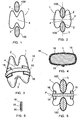
- Figures 1 and 2 show an existing flexible interspinous implant 1, capable of being inserted between the spinous processes 100 of two vertebrae so as to be able to cushion the posterior movement of these vertebrae during extension of the spinal column.
- the implant 1 is substantially in the shape of an "H," i.e., it includes an upper recess 2 and a lower recess 3 capable of receiving the spinous processes 100; it is formed from a block of flexible material, made of silicone in particular, possibly contained inside a casing made of a woven material, made of polyester in particular.
- the spinous processes 100 exert opposing pressures on the centre section 4 of the implant 1, which can be significant in patients who are strong or who have localised compensatory hyperlordosis. Such pressures produce a lateral creep of the implant 1 material, resulting in a thinning of the centre section 4 that does not enable a sufficient capability for cushioning the posterior movements of the vertebrae.
- the areas Z of the respective spinous processes 100 bearing against the implant 1 define a longitudinal axis L of the implant 1, and a plane P perpendicular to this longitudinal axis.
- Figures 3 to 6 show a device 10 for treating vertebrae, including an interspinous implant 1 such as the one cited above.
- the device further includes a restraining cerclage 15 and two lateral bearing distribution plates 16.
- the cerclage 15 is made of a stretchable material, in particular a synthetic or metallic material. It has a flattened cross-section forming a planar surface for bearing against the implant 1.
- this cerclage 15 is intended to be adjustably engaged around said centre section 4 of the implant 1, in a plane perpendicular to the longitudinal median plane of the implant, i.e., the plane of symmetry of the implant 1 passing through the bottoms of the recesses 2, 3.
- the cerclage 15 can consist of a continuous strip, as shown in figures 3 or 5 , and is put into place before inserting the implant 1 into the body of the patient, or can be put into place on the implant 1 after the latter has been placed on the spinal column of the patient.
- the cerclage 15 can, in particular, be made of a metallic material and, as shown in figure 4 , one of its ends can include a hole into which the other of its ends can be inserted, this other end then being folded over itself and crimped in order to ensure closure of the cerclage 15.
- Each plate 16 is made of a rigid and heavy-duty material, in particular a synthetic or metallic material. As shown more particularly in figure 4 , when seen from a profile view, it has a "C" shape capable of widely wrapping around a corresponding lateral area of the implant 1, i.e., of extending not only over this lateral area but also partially over the posterior and anterior faces of the implant 1.
- the two plates 16 are intended to be inserted between the implant 1 and the cerclage 15 and function to increase the contact surface between the cerclage 15 and the implant 1.
- Figure 6 shows that, on its outside face, at least one plate 16 can include a recess 20 for receiving the cerclage 15, making it possible to wedge the cerclage 15 in relation to the plate 16. This wedging ensures the positioning of the cerclages 15 and the plate 16 in relation to each other and prevents a risk of this cerclage 15 slipping over the course of time, in relation to the implant 1.
- the cerclage 15 makes it possible to restrain the lateral deformation of the implant 1 at the centre section 4. This restraint makes it possible to impede the lateral deformation that the implant 1 would otherwise experience, and to thus preserve a sufficient cushioning capability at the centre section 4, even in the case of strong compressive forces, such as can those that can exist in patients who are strong or who suffer from hyperlordosis.
- the plates 16 strengthen the restraining function of the cerclage 15 and make it possible to increase the contact surface between the cerclage 15 and the implant 1, in order to eliminate any sharing risk of the implant material.
- Their wrap-around shapes further the lateral restraint of the implant 1 and enable a certain degree of retention of these plates 16 on the implant 1, facilitating the installation of the device.
- the invention provides a device for treating vertebrae whose interspinous implant has a sufficient cushioning capability in every instance, in particular in the case of patients who are large or who have localized compensatory hyperlordosis.
Landscapes
- Health & Medical Sciences (AREA)
- Orthopedic Medicine & Surgery (AREA)
- Life Sciences & Earth Sciences (AREA)
- Neurology (AREA)
- Surgery (AREA)
- Heart & Thoracic Surgery (AREA)
- Engineering & Computer Science (AREA)
- Biomedical Technology (AREA)
- Nuclear Medicine, Radiotherapy & Molecular Imaging (AREA)
- Medical Informatics (AREA)
- Molecular Biology (AREA)
- Animal Behavior & Ethology (AREA)
- General Health & Medical Sciences (AREA)
- Public Health (AREA)
- Veterinary Medicine (AREA)
- Prostheses (AREA)
- Micro-Organisms Or Cultivation Processes Thereof (AREA)
- Steroid Compounds (AREA)
Claims (10)
- Vorrichtung (10) zur Behandlung von Wirbeln, mit einem Implantat (1), das eine flexible Struktur aufweist, wobei die Vorrichtung zwischen die Dornfortsätze (100) von zwei Wirbeln eingeführt werden kann, wobei die Flächen (Z) dieser entsprechenden Dornfortsätze (100) an dem Implantat (1) lagern und eine Längsachse (L) des Implantats definieren, dadurch gekennzeichnet, dass die Vorrichtung mindestens eine Cerclage (15) aufweist, die einen anpassbaren Eingriff um das Implantat (1) an einem Mittelabschnitt (4) des Implantats (1) in einer Ebene (P) herstellen kann, die senkrecht zu der genannten Längsachse (L) ist; wobei die Cerclage (15) aus einem Material besteht, das in die umfängliche Richtung der Cerclage (15) nicht ausdehnbar ist, so dass es möglich ist, eine Verformung des Implantats (1) an dem Mittelabschnitt (4) innerhalb der genannten Ebene (P) zu verhindern, während auf diesen Mittelabschnitt entgegengesetzt wirkende Kompressionskräfte wirken, die durch die Dornfortsätze der Wirbel während einer posterioren Bewebung der Wirbelsäule ausgeübt werden.
- Vorrichtung (10) nach Anspruch 1, dadurch gekennzeichnet, dass die Cerclage (15) einen abgeflachten Querschnitt aufweist, der eine planare Oberfläche zum Anliegen an dem Implantat bildet.
- Vorrichtung (10) nach Anspruch 2, dadurch gekennzeichnet, dass die Cerclage (15) abgerundete Kanten an der genannten planaren Oberfläche zum Anliegen aufweist.
- Vorrichtung (10) nach einem der Ansprüche 1 bis 3, dadurch gekennzeichnet, dass die Cerclage (15) nahe mindestens einem ihrer Teilstücke, der an die lateralen Bereiche des Implantats (1) geführt werden soll, eine erhöhte Breite aufweist.
- Vorrichtung (10) nach einem der Ansprüche 1 bis 3, dadurch gekennzeichnet, dass diese eine Lagerplatte (16) aufweist, die aus einem steifen und für hohe Anforderungen geeigneten Material besteht, wobei die Platte dazu dient, zwischen dem Implantat (1) und der Cerclage (15) eingeführt zu werden.
- Vorrichtung (10) nach Anspruch 4 oder Anspruch 5, dadurch gekennzeichnet, dass das genannte Teilstück der Cerclage (15) mit vergrößerter Breite oder die genannte Platte (16) eine Abmessung aufweisen kann, so dass das Teilstück oder die Platte sich großteils um einen entsprechenden lateralen Bereich des Implantats (1) wickeln kann, d.h. sich nicht nur über diesen lateralen Bereich erstrecken kann, sonder auch teilweise über die posterioren und anterioren Seiten des Implantats (1).
- Vorrichtung (10) nach Anspruch 5 oder Anspruch 6, dadurch gekennzeichnet, dass mindestens eine Platte (16) an ihrer Außenseite eine Aussparung zur Aufnahme der Cerclage (15) aufweist.
- Vorrichtung (10) nach einem der Ansprüche 5 bis 7, dadurch gekennzeichnet, dass die Platte (16) und/oder die Cerclage (15) Formen aufweisen, welche den Zusammenbau der Platte (16) und der Cerclage (15) ermöglichen, im Besonderen durch gegenseitiges Einschnappen oder kraftschlüssige Verbindung miteinander mit selbstverriegelnder Wirkung.
- Vorrichtung (10) nach einem der Ansprüche 1 bis 8, dadurch gekennzeichnet, dass die Cerclage (15) aus einem Endlosmaterialstreifen besteht, der über das Implantat (1) eingeführt wird.
- Vorrichtung (10) nach einem der Ansprüche 1 bis 8, dadurch gekennzeichnet, dass die Cerclage (15) aus einem Materialstreifen besteht, dessen Enden nach dem Einbau miteinander verbunden werden.
Applications Claiming Priority (3)
| Application Number | Priority Date | Filing Date | Title |
|---|---|---|---|
| FR0603266A FR2899788B1 (fr) | 2006-04-13 | 2006-04-13 | Materiel de traitement de vertebres, comprenant un implant interepineux |
| US79190606P | 2006-04-14 | 2006-04-14 | |
| PCT/IB2007/000982 WO2007119157A1 (en) | 2006-04-13 | 2007-04-03 | Device for treating vertebrae, including an interspinous implant |
Publications (3)
| Publication Number | Publication Date |
|---|---|
| EP2004073A1 EP2004073A1 (de) | 2008-12-24 |
| EP2004073B1 true EP2004073B1 (de) | 2010-03-17 |
| EP2004073B8 EP2004073B8 (de) | 2010-05-12 |
Family
ID=38236526
Family Applications (1)
| Application Number | Title | Priority Date | Filing Date |
|---|---|---|---|
| EP07734301A Active EP2004073B8 (de) | 2006-04-13 | 2007-04-03 | Vorrichtung zur behandlung von wirbeln, einschliesslich interspinöses implantat |
Country Status (8)
| Country | Link |
|---|---|
| US (1) | US20090275982A1 (de) |
| EP (1) | EP2004073B8 (de) |
| JP (1) | JP5075194B2 (de) |
| AT (1) | ATE460891T1 (de) |
| AU (2) | AU2007238347B2 (de) |
| DE (1) | DE602007005360D1 (de) |
| FR (1) | FR2899788B1 (de) |
| WO (1) | WO2007119157A1 (de) |
Families Citing this family (7)
| Publication number | Priority date | Publication date | Assignee | Title |
|---|---|---|---|---|
| US8241330B2 (en) | 2007-01-11 | 2012-08-14 | Lanx, Inc. | Spinous process implants and associated methods |
| US9055981B2 (en) | 2004-10-25 | 2015-06-16 | Lanx, Inc. | Spinal implants and methods |
| US8262698B2 (en) | 2006-03-16 | 2012-09-11 | Warsaw Orthopedic, Inc. | Expandable device for insertion between anatomical structures and a procedure utilizing same |
| US9265532B2 (en) | 2007-01-11 | 2016-02-23 | Lanx, Inc. | Interspinous implants and methods |
| EP2413825A4 (de) | 2009-03-31 | 2013-12-11 | Lanx Inc | Dornfortsatzimplantate und zugehörige verfahren |
| FR2977139B1 (fr) | 2011-06-30 | 2014-08-22 | Ldr Medical | Implant inter-epineux et instrument d’implantation |
| US11812923B2 (en) | 2011-10-07 | 2023-11-14 | Alan Villavicencio | Spinal fixation device |
Family Cites Families (101)
| Publication number | Priority date | Publication date | Assignee | Title |
|---|---|---|---|---|
| US2677369A (en) * | 1952-03-26 | 1954-05-04 | Fred L Knowles | Apparatus for treatment of the spinal column |
| US3648691A (en) * | 1970-02-24 | 1972-03-14 | Univ Colorado State Res Found | Method of applying vertebral appliance |
| US4011602A (en) * | 1975-10-06 | 1977-03-15 | Battelle Memorial Institute | Porous expandable device for attachment to bone tissue |
| PL114098B1 (en) * | 1978-04-14 | 1981-01-31 | Wyzsza Szkola Inzynierska | Apparatus for correcting spinal curvature |
| GB8333442D0 (en) * | 1983-12-15 | 1984-01-25 | Showell A W Sugicraft Ltd | Devices for spinal fixation |
| US4604995A (en) * | 1984-03-30 | 1986-08-12 | Stephens David C | Spinal stabilizer |
| US4643178A (en) * | 1984-04-23 | 1987-02-17 | Fabco Medical Products, Inc. | Surgical wire and method for the use thereof |
| US4573454A (en) * | 1984-05-17 | 1986-03-04 | Hoffman Gregory A | Spinal fixation apparatus |
| FR2575059B1 (fr) * | 1984-12-21 | 1988-11-10 | Daher Youssef | Dispositif d'etaiement utilisable dans une prothese vertebrale |
| SE458417B (sv) * | 1985-08-15 | 1989-04-03 | Sven Olerud | Fixationsinstrument avsett foer anvaendning vid ryggoperationer |
| WO1987007134A1 (en) * | 1986-05-30 | 1987-12-03 | John Bumpus | Distraction rods |
| FR2623085B1 (fr) * | 1987-11-16 | 1992-08-14 | Breard Francis | Implant chirurgical pour limiter le mouvement relatif des vertebres |
| US5609635A (en) * | 1988-06-28 | 1997-03-11 | Michelson; Gary K. | Lordotic interbody spinal fusion implants |
| US5201734A (en) * | 1988-12-21 | 1993-04-13 | Zimmer, Inc. | Spinal locking sleeve assembly |
| FR2642645B1 (fr) * | 1989-02-03 | 1992-08-14 | Breard Francis | Stabilisateur intervertebral souple ainsi que procede et appareillage pour le controle de sa tension avant mise en place sur le rachis |
| US5098433A (en) * | 1989-04-12 | 1992-03-24 | Yosef Freedland | Winged compression bolt orthopedic fastener |
| US5345927A (en) * | 1990-03-02 | 1994-09-13 | Bonutti Peter M | Arthroscopic retractors |
| US5390683A (en) * | 1991-02-22 | 1995-02-21 | Pisharodi; Madhavan | Spinal implantation methods utilizing a middle expandable implant |
| CH686610A5 (de) * | 1991-10-18 | 1996-05-15 | Pina Vertriebs Ag | Kompressionsimplantat. |
| FR2693364B1 (fr) * | 1992-07-07 | 1995-06-30 | Erpios Snc | Prothese intervertebrale permettant une stabilisation des contraintes rotatoires et de flexion-extension. |
| GB9217578D0 (en) * | 1992-08-19 | 1992-09-30 | Surgicarft Ltd | Surgical implants,etc |
| DE9213656U1 (de) * | 1992-10-09 | 1992-12-03 | Angiomed AG, 7500 Karlsruhe | Stent-Set |
| DE69330909T2 (de) * | 1992-11-12 | 2002-06-20 | Neville Alleyne | Einrichtung zum schutz des herzens |
| US5306275A (en) * | 1992-12-31 | 1994-04-26 | Bryan Donald W | Lumbar spine fixation apparatus and method |
| US5540703A (en) * | 1993-01-06 | 1996-07-30 | Smith & Nephew Richards Inc. | Knotted cable attachment apparatus formed of braided polymeric fibers |
| US5496318A (en) * | 1993-01-08 | 1996-03-05 | Advanced Spine Fixation Systems, Inc. | Interspinous segmental spine fixation device |
| US5415661A (en) * | 1993-03-24 | 1995-05-16 | University Of Miami | Implantable spinal assist device |
| FR2717675B1 (fr) * | 1994-03-24 | 1996-05-03 | Jean Taylor | Cale inter-épineuse. |
| FR2722980B1 (fr) * | 1994-07-26 | 1996-09-27 | Samani Jacques | Implant vertebral inter-epineux |
| FR2730156B1 (fr) * | 1995-02-03 | 1997-04-30 | Textile Hi Tec | Cale inter epineuse |
| US6102922A (en) * | 1995-09-22 | 2000-08-15 | Kirk Promotions Limited | Surgical method and device for reducing the food intake of patient |
| US5716416A (en) * | 1996-09-10 | 1998-02-10 | Lin; Chih-I | Artificial intervertebral disk and method for implanting the same |
| US6190414B1 (en) * | 1996-10-31 | 2001-02-20 | Surgical Dynamics Inc. | Apparatus for fusion of adjacent bone structures |
| US6068630A (en) * | 1997-01-02 | 2000-05-30 | St. Francis Medical Technologies, Inc. | Spine distraction implant |
| US7201751B2 (en) * | 1997-01-02 | 2007-04-10 | St. Francis Medical Technologies, Inc. | Supplemental spine fixation device |
| US5860977A (en) * | 1997-01-02 | 1999-01-19 | Saint Francis Medical Technologies, Llc | Spine distraction implant and method |
| US6695842B2 (en) * | 1997-10-27 | 2004-02-24 | St. Francis Medical Technologies, Inc. | Interspinous process distraction system and method with positionable wing and method |
| IL128261A0 (en) * | 1999-01-27 | 1999-11-30 | Disc O Tech Medical Tech Ltd | Expandable element |
| US6022376A (en) * | 1997-06-06 | 2000-02-08 | Raymedica, Inc. | Percutaneous prosthetic spinal disc nucleus and method of manufacture |
| CA2307888C (en) * | 1997-10-27 | 2007-09-18 | Saint Francis Medical Technologies, Inc. | Spine distraction implant |
| FR2774581B1 (fr) * | 1998-02-10 | 2000-08-11 | Dimso Sa | Stabilisateur interepineux a fixer a des apophyses epineuses de deux vertebres |
| FR2775183B1 (fr) * | 1998-02-20 | 2000-08-04 | Jean Taylor | Prothese inter-epineuse |
| US6352537B1 (en) * | 1998-09-17 | 2002-03-05 | Electro-Biology, Inc. | Method and apparatus for spinal fixation |
| US6554833B2 (en) * | 1998-10-26 | 2003-04-29 | Expanding Orthopedics, Inc. | Expandable orthopedic device |
| BR9805340B1 (pt) * | 1998-12-14 | 2009-01-13 | inserto de expansço variÁvel para estabilizaÇço de coluna vertebral. | |
| US6520991B2 (en) * | 1999-05-11 | 2003-02-18 | Donald R. Huene | Expandable implant for inter-vertebral stabilization, and a method of stabilizing vertebrae |
| US6214050B1 (en) * | 1999-05-11 | 2001-04-10 | Donald R. Huene | Expandable implant for inter-bone stabilization and adapted to extrude osteogenic material, and a method of stabilizing bones while extruding osteogenic material |
| US6419704B1 (en) * | 1999-10-08 | 2002-07-16 | Bret Ferree | Artificial intervertebral disc replacement methods and apparatus |
| FR2799640B1 (fr) * | 1999-10-15 | 2002-01-25 | Spine Next Sa | Implant intervetebral |
| WO2001034045A1 (en) * | 1999-11-11 | 2001-05-17 | Synthes Ag Chur | Radially expandable intramedullary nail |
| US6402750B1 (en) * | 2000-04-04 | 2002-06-11 | Spinlabs, Llc | Devices and methods for the treatment of spinal disorders |
| FR2811540B1 (fr) * | 2000-07-12 | 2003-04-25 | Spine Next Sa | Implant intervertebral amortissant |
| US6733531B1 (en) * | 2000-10-20 | 2004-05-11 | Sdgi Holdings, Inc. | Anchoring devices and implants for intervertebral disc augmentation |
| WO2002047587A2 (en) * | 2000-10-25 | 2002-06-20 | Sdgi Holdings, Inc. | Vertically expanding intervertebral body fusion device |
| US6582467B1 (en) * | 2000-10-31 | 2003-06-24 | Vertelink Corporation | Expandable fusion cage |
| US6666891B2 (en) * | 2000-11-13 | 2003-12-23 | Frank H. Boehm, Jr. | Device and method for lumbar interbody fusion |
| US6579319B2 (en) * | 2000-11-29 | 2003-06-17 | Medicinelodge, Inc. | Facet joint replacement |
| GB0102141D0 (en) * | 2001-01-27 | 2001-03-14 | Davies John B C | Improvements in or relating to expandable bone nails |
| US6364883B1 (en) * | 2001-02-23 | 2002-04-02 | Albert N. Santilli | Spinous process clamp for spinal fusion and method of operation |
| FR2822051B1 (fr) * | 2001-03-13 | 2004-02-27 | Spine Next Sa | Implant intervertebral a fixation auto-bloquante |
| US6582433B2 (en) * | 2001-04-09 | 2003-06-24 | St. Francis Medical Technologies, Inc. | Spine fixation device and method |
| US6375682B1 (en) * | 2001-08-06 | 2002-04-23 | Lewis W. Fleischmann | Collapsible, rotatable and expandable spinal hydraulic prosthetic device |
| US6736815B2 (en) * | 2001-09-06 | 2004-05-18 | Core Medical, Inc. | Apparatus and methods for treating spinal discs |
| FR2832917B1 (fr) * | 2001-11-30 | 2004-09-24 | Spine Next Sa | Implant intervertebral a cale elastiquement deformable |
| JP2005516648A (ja) * | 2001-12-13 | 2005-06-09 | エスディージーアイ・ホールディングス・インコーポレーテッド | インプラントを椎骨空間内に導入する器具及び方法 |
| US6733534B2 (en) * | 2002-01-29 | 2004-05-11 | Sdgi Holdings, Inc. | System and method for spine spacing |
| US6923830B2 (en) * | 2002-02-02 | 2005-08-02 | Gary K. Michelson | Spinal fusion implant having deployable bone engaging projections |
| JP3708883B2 (ja) * | 2002-02-08 | 2005-10-19 | 昭和医科工業株式会社 | 椎体間隔保持具 |
| EP1346708A1 (de) * | 2002-03-20 | 2003-09-24 | A-Spine Holding Group Corp. | Vorrichtung mit drei Haken zur Fixierung der Wirbelsäule |
| US7048736B2 (en) * | 2002-05-17 | 2006-05-23 | Sdgi Holdings, Inc. | Device for fixation of spinous processes |
| FR2844179B1 (fr) * | 2002-09-10 | 2004-12-03 | Jean Taylor | Ensemble de soutien vertebral posterieur |
| US7833246B2 (en) * | 2002-10-29 | 2010-11-16 | Kyphon SÀRL | Interspinous process and sacrum implant and method |
| US20060064165A1 (en) * | 2004-09-23 | 2006-03-23 | St. Francis Medical Technologies, Inc. | Interspinous process implant including a binder and method of implantation |
| US7549999B2 (en) * | 2003-05-22 | 2009-06-23 | Kyphon Sarl | Interspinous process distraction implant and method of implantation |
| US6723126B1 (en) * | 2002-11-01 | 2004-04-20 | Sdgi Holdings, Inc. | Laterally expandable cage |
| US6685742B1 (en) * | 2002-11-12 | 2004-02-03 | Roger P. Jackson | Articulated anterior expandable spinal fusion cage system |
| FR2851154B1 (fr) * | 2003-02-19 | 2006-07-07 | Sdgi Holding Inc | Dispositif inter-epineux pour freiner les mouvements de deux vertebres successives, et procede de fabrication d'un coussin lui etant destine |
| WO2005044152A1 (en) * | 2003-11-07 | 2005-05-19 | Impliant Ltd. | Spinal prostheses |
| US7217293B2 (en) * | 2003-11-21 | 2007-05-15 | Warsaw Orthopedic, Inc. | Expandable spinal implant |
| WO2005072301A2 (en) * | 2004-01-26 | 2005-08-11 | Reiley Mark A | Percutaneous spine distraction implant systems and methods |
| US7641664B2 (en) * | 2004-02-12 | 2010-01-05 | Warsaw Orthopedic, Inc. | Surgical instrumentation and method for treatment of a spinal structure |
| FR2871366A1 (fr) * | 2004-06-09 | 2005-12-16 | Ceravic Soc Par Actions Simpli | Implant expansible prothetique osseux |
| US7776091B2 (en) * | 2004-06-30 | 2010-08-17 | Depuy Spine, Inc. | Adjustable posterior spinal column positioner |
| US20060015181A1 (en) * | 2004-07-19 | 2006-01-19 | Biomet Merck France (50% Interest) | Interspinous vertebral implant |
| US7951153B2 (en) * | 2004-10-05 | 2011-05-31 | Samy Abdou | Devices and methods for inter-vertebral orthopedic device placement |
| US8167944B2 (en) * | 2004-10-20 | 2012-05-01 | The Board Of Trustees Of The Leland Stanford Junior University | Systems and methods for posterior dynamic stabilization of the spine |
| US9023084B2 (en) * | 2004-10-20 | 2015-05-05 | The Board Of Trustees Of The Leland Stanford Junior University | Systems and methods for stabilizing the motion or adjusting the position of the spine |
| US8123807B2 (en) * | 2004-10-20 | 2012-02-28 | Vertiflex, Inc. | Systems and methods for posterior dynamic stabilization of the spine |
| US8012207B2 (en) * | 2004-10-20 | 2011-09-06 | Vertiflex, Inc. | Systems and methods for posterior dynamic stabilization of the spine |
| US8162985B2 (en) * | 2004-10-20 | 2012-04-24 | The Board Of Trustees Of The Leland Stanford Junior University | Systems and methods for posterior dynamic stabilization of the spine |
| US8317864B2 (en) * | 2004-10-20 | 2012-11-27 | The Board Of Trustees Of The Leland Stanford Junior University | Systems and methods for posterior dynamic stabilization of the spine |
| US20060089719A1 (en) * | 2004-10-21 | 2006-04-27 | Trieu Hai H | In situ formation of intervertebral disc implants |
| EP1807012B1 (de) * | 2004-10-25 | 2016-07-06 | Lanx, LLC | Vorrichtungen zur interspinalen distraktion |
| US7918875B2 (en) * | 2004-10-25 | 2011-04-05 | Lanx, Inc. | Interspinous distraction devices and associated methods of insertion |
| US20060106381A1 (en) * | 2004-11-18 | 2006-05-18 | Ferree Bret A | Methods and apparatus for treating spinal stenosis |
| US8172855B2 (en) * | 2004-11-24 | 2012-05-08 | Abdou M S | Devices and methods for inter-vertebral orthopedic device placement |
| WO2006066228A2 (en) * | 2004-12-16 | 2006-06-22 | Innovative Spinal Technologies | Expandable implants for spinal disc replacement |
| US8038698B2 (en) * | 2005-02-17 | 2011-10-18 | Kphon Sarl | Percutaneous spinal implants and methods |
| US20060195102A1 (en) * | 2005-02-17 | 2006-08-31 | Malandain Hugues F | Apparatus and method for treatment of spinal conditions |
| US20060184248A1 (en) * | 2005-02-17 | 2006-08-17 | Edidin Avram A | Percutaneous spinal implants and methods |
| US7383639B2 (en) * | 2005-07-12 | 2008-06-10 | Medtronic Spine Llc | Measurement instrument for percutaneous surgery |
-
2006
- 2006-04-13 FR FR0603266A patent/FR2899788B1/fr not_active Expired - Fee Related
-
2007
- 2007-04-03 EP EP07734301A patent/EP2004073B8/de active Active
- 2007-04-03 AT AT07734301T patent/ATE460891T1/de not_active IP Right Cessation
- 2007-04-03 WO PCT/IB2007/000982 patent/WO2007119157A1/en not_active Ceased
- 2007-04-03 DE DE602007005360T patent/DE602007005360D1/de active Active
- 2007-04-03 JP JP2009504851A patent/JP5075194B2/ja not_active Expired - Fee Related
- 2007-04-03 US US12/296,958 patent/US20090275982A1/en not_active Abandoned
- 2007-04-03 AU AU2007238347A patent/AU2007238347B2/en not_active Ceased
-
2010
- 2010-03-29 AU AU2010201253A patent/AU2010201253A1/en not_active Abandoned
Also Published As
| Publication number | Publication date |
|---|---|
| EP2004073B8 (de) | 2010-05-12 |
| DE602007005360D1 (de) | 2010-04-29 |
| JP5075194B2 (ja) | 2012-11-14 |
| WO2007119157A1 (en) | 2007-10-25 |
| FR2899788B1 (fr) | 2008-07-04 |
| AU2010201253A1 (en) | 2010-04-22 |
| AU2007238347B2 (en) | 2010-02-11 |
| EP2004073A1 (de) | 2008-12-24 |
| ATE460891T1 (de) | 2010-04-15 |
| FR2899788A1 (fr) | 2007-10-19 |
| JP2009533123A (ja) | 2009-09-17 |
| US20090275982A1 (en) | 2009-11-05 |
| AU2007238347A1 (en) | 2007-10-25 |
Similar Documents
| Publication | Publication Date | Title |
|---|---|---|
| AU2007238347B2 (en) | Device for treating vertebrae, including an interspinous implant | |
| AU2004268404B2 (en) | Intervertebral implant for the lumbosacral articulation | |
| AU698093C (en) | A device to stabilise the lamina | |
| US6312431B1 (en) | Vertebrae linking system | |
| EP1761177B1 (de) | System zum schutz von neurovaskulären strukturen | |
| AU2002349962B2 (en) | Bone compression devices and systems and methods of contouring and using same | |
| US6635087B2 (en) | Laminoplasty implants and methods of use | |
| US6626944B1 (en) | Interspinous prosthesis | |
| US8475497B2 (en) | Spinous process plate and connector assembly and method | |
| EP1890616B1 (de) | Anteriore halswirbelplatte | |
| US20060015181A1 (en) | Interspinous vertebral implant | |
| US20080154312A1 (en) | Active settling plate with elastomeric members and method of use | |
| US20040064184A1 (en) | Laminoplasty cage | |
| JP2010042287A (ja) | 椎骨インプラント | |
| JP2008541996A (ja) | 脊椎安定化のためのインプラント及びその使用方法 | |
| JP2010538752A (ja) | 棘状突起間スペーサ | |
| WO2002024086A1 (en) | Cable-anchor system for spinal fixation | |
| KR20080035574A (ko) | 자체 태핑된 고정 돌출부를 갖는 추간 인공 보철물 | |
| WO2002064059A2 (en) | Orthopedic implant and method for orthopedic treatment | |
| CA2554638A1 (en) | Orthopedic distraction implants and techniques | |
| US20080215096A1 (en) | Devices to Stabilise the Lamina | |
| US20160008038A1 (en) | Methods and systems for constraint of multiple spine segments | |
| AU2012244234B2 (en) | A device for treating the spine |
Legal Events
| Date | Code | Title | Description |
|---|---|---|---|
| PUAI | Public reference made under article 153(3) epc to a published international application that has entered the european phase |
Free format text: ORIGINAL CODE: 0009012 |
|
| 17P | Request for examination filed |
Effective date: 20081020 |
|
| AK | Designated contracting states |
Kind code of ref document: A1 Designated state(s): AT BE BG CH CY CZ DE DK EE ES FI FR GB GR HU IE IS IT LI LT LU LV MC MT NL PL PT RO SE SI SK TR |
|
| GRAP | Despatch of communication of intention to grant a patent |
Free format text: ORIGINAL CODE: EPIDOSNIGR1 |
|
| GRAS | Grant fee paid |
Free format text: ORIGINAL CODE: EPIDOSNIGR3 |
|
| GRAA | (expected) grant |
Free format text: ORIGINAL CODE: 0009210 |
|
| AK | Designated contracting states |
Kind code of ref document: B1 Designated state(s): AT BE BG CH CY CZ DE DK EE ES FI FR GB GR HU IE IS IT LI LT LU LV MC MT NL PL PT RO SE SI SK TR |
|
| REG | Reference to a national code |
Ref country code: GB Ref legal event code: FG4D |
|
| RAP2 | Party data changed (patent owner data changed or rights of a patent transferred) |
Owner name: KYPHON SARL |
|
| RIN2 | Information on inventor provided after grant (corrected) |
Inventor name: KYPHON SARL |
|
| REG | Reference to a national code |
Ref country code: CH Ref legal event code: EP |
|
| REG | Reference to a national code |
Ref country code: IE Ref legal event code: FG4D |
|
| REF | Corresponds to: |
Ref document number: 602007005360 Country of ref document: DE Date of ref document: 20100429 Kind code of ref document: P |
|
| REG | Reference to a national code |
Ref country code: NL Ref legal event code: VDEP Effective date: 20100317 |
|
| PG25 | Lapsed in a contracting state [announced via postgrant information from national office to epo] |
Ref country code: LT Free format text: LAPSE BECAUSE OF FAILURE TO SUBMIT A TRANSLATION OF THE DESCRIPTION OR TO PAY THE FEE WITHIN THE PRESCRIBED TIME-LIMIT Effective date: 20100317 |
|
| LTIE | Lt: invalidation of european patent or patent extension |
Effective date: 20100317 |
|
| PG25 | Lapsed in a contracting state [announced via postgrant information from national office to epo] |
Ref country code: PL Free format text: LAPSE BECAUSE OF FAILURE TO SUBMIT A TRANSLATION OF THE DESCRIPTION OR TO PAY THE FEE WITHIN THE PRESCRIBED TIME-LIMIT Effective date: 20100317 Ref country code: LV Free format text: LAPSE BECAUSE OF FAILURE TO SUBMIT A TRANSLATION OF THE DESCRIPTION OR TO PAY THE FEE WITHIN THE PRESCRIBED TIME-LIMIT Effective date: 20100317 Ref country code: FI Free format text: LAPSE BECAUSE OF FAILURE TO SUBMIT A TRANSLATION OF THE DESCRIPTION OR TO PAY THE FEE WITHIN THE PRESCRIBED TIME-LIMIT Effective date: 20100317 Ref country code: SI Free format text: LAPSE BECAUSE OF FAILURE TO SUBMIT A TRANSLATION OF THE DESCRIPTION OR TO PAY THE FEE WITHIN THE PRESCRIBED TIME-LIMIT Effective date: 20100317 Ref country code: AT Free format text: LAPSE BECAUSE OF FAILURE TO SUBMIT A TRANSLATION OF THE DESCRIPTION OR TO PAY THE FEE WITHIN THE PRESCRIBED TIME-LIMIT Effective date: 20100317 |
|
| PG25 | Lapsed in a contracting state [announced via postgrant information from national office to epo] |
Ref country code: ES Free format text: LAPSE BECAUSE OF FAILURE TO SUBMIT A TRANSLATION OF THE DESCRIPTION OR TO PAY THE FEE WITHIN THE PRESCRIBED TIME-LIMIT Effective date: 20100628 Ref country code: NL Free format text: LAPSE BECAUSE OF FAILURE TO SUBMIT A TRANSLATION OF THE DESCRIPTION OR TO PAY THE FEE WITHIN THE PRESCRIBED TIME-LIMIT Effective date: 20100317 Ref country code: EE Free format text: LAPSE BECAUSE OF FAILURE TO SUBMIT A TRANSLATION OF THE DESCRIPTION OR TO PAY THE FEE WITHIN THE PRESCRIBED TIME-LIMIT Effective date: 20100317 Ref country code: BE Free format text: LAPSE BECAUSE OF FAILURE TO SUBMIT A TRANSLATION OF THE DESCRIPTION OR TO PAY THE FEE WITHIN THE PRESCRIBED TIME-LIMIT Effective date: 20100317 Ref country code: CY Free format text: LAPSE BECAUSE OF FAILURE TO SUBMIT A TRANSLATION OF THE DESCRIPTION OR TO PAY THE FEE WITHIN THE PRESCRIBED TIME-LIMIT Effective date: 20100317 Ref country code: GR Free format text: LAPSE BECAUSE OF FAILURE TO SUBMIT A TRANSLATION OF THE DESCRIPTION OR TO PAY THE FEE WITHIN THE PRESCRIBED TIME-LIMIT Effective date: 20100618 Ref country code: RO Free format text: LAPSE BECAUSE OF FAILURE TO SUBMIT A TRANSLATION OF THE DESCRIPTION OR TO PAY THE FEE WITHIN THE PRESCRIBED TIME-LIMIT Effective date: 20100317 Ref country code: SE Free format text: LAPSE BECAUSE OF FAILURE TO SUBMIT A TRANSLATION OF THE DESCRIPTION OR TO PAY THE FEE WITHIN THE PRESCRIBED TIME-LIMIT Effective date: 20100317 |
|
| PG25 | Lapsed in a contracting state [announced via postgrant information from national office to epo] |
Ref country code: CZ Free format text: LAPSE BECAUSE OF FAILURE TO SUBMIT A TRANSLATION OF THE DESCRIPTION OR TO PAY THE FEE WITHIN THE PRESCRIBED TIME-LIMIT Effective date: 20100317 Ref country code: BG Free format text: LAPSE BECAUSE OF FAILURE TO SUBMIT A TRANSLATION OF THE DESCRIPTION OR TO PAY THE FEE WITHIN THE PRESCRIBED TIME-LIMIT Effective date: 20100617 Ref country code: MC Free format text: LAPSE BECAUSE OF NON-PAYMENT OF DUE FEES Effective date: 20100430 Ref country code: IS Free format text: LAPSE BECAUSE OF FAILURE TO SUBMIT A TRANSLATION OF THE DESCRIPTION OR TO PAY THE FEE WITHIN THE PRESCRIBED TIME-LIMIT Effective date: 20100717 Ref country code: SK Free format text: LAPSE BECAUSE OF FAILURE TO SUBMIT A TRANSLATION OF THE DESCRIPTION OR TO PAY THE FEE WITHIN THE PRESCRIBED TIME-LIMIT Effective date: 20100317 |
|
| PLBE | No opposition filed within time limit |
Free format text: ORIGINAL CODE: 0009261 |
|
| STAA | Information on the status of an ep patent application or granted ep patent |
Free format text: STATUS: NO OPPOSITION FILED WITHIN TIME LIMIT |
|
| PG25 | Lapsed in a contracting state [announced via postgrant information from national office to epo] |
Ref country code: DK Free format text: LAPSE BECAUSE OF FAILURE TO SUBMIT A TRANSLATION OF THE DESCRIPTION OR TO PAY THE FEE WITHIN THE PRESCRIBED TIME-LIMIT Effective date: 20100317 Ref country code: PT Free format text: LAPSE BECAUSE OF FAILURE TO SUBMIT A TRANSLATION OF THE DESCRIPTION OR TO PAY THE FEE WITHIN THE PRESCRIBED TIME-LIMIT Effective date: 20100719 Ref country code: IE Free format text: LAPSE BECAUSE OF NON-PAYMENT OF DUE FEES Effective date: 20100403 |
|
| 26N | No opposition filed |
Effective date: 20101220 |
|
| PG25 | Lapsed in a contracting state [announced via postgrant information from national office to epo] |
Ref country code: IT Free format text: LAPSE BECAUSE OF NON-PAYMENT OF DUE FEES Effective date: 20100403 |
|
| PG25 | Lapsed in a contracting state [announced via postgrant information from national office to epo] |
Ref country code: MT Free format text: LAPSE BECAUSE OF FAILURE TO SUBMIT A TRANSLATION OF THE DESCRIPTION OR TO PAY THE FEE WITHIN THE PRESCRIBED TIME-LIMIT Effective date: 20100317 |
|
| PGFP | Annual fee paid to national office [announced via postgrant information from national office to epo] |
Ref country code: GB Payment date: 20110328 Year of fee payment: 5 |
|
| PGFP | Annual fee paid to national office [announced via postgrant information from national office to epo] |
Ref country code: IT Payment date: 20110423 Year of fee payment: 5 |
|
| REG | Reference to a national code |
Ref country code: CH Ref legal event code: PL |
|
| PG25 | Lapsed in a contracting state [announced via postgrant information from national office to epo] |
Ref country code: CH Free format text: LAPSE BECAUSE OF NON-PAYMENT OF DUE FEES Effective date: 20110430 Ref country code: LI Free format text: LAPSE BECAUSE OF NON-PAYMENT OF DUE FEES Effective date: 20110430 |
|
| PG25 | Lapsed in a contracting state [announced via postgrant information from national office to epo] |
Ref country code: HU Free format text: LAPSE BECAUSE OF FAILURE TO SUBMIT A TRANSLATION OF THE DESCRIPTION OR TO PAY THE FEE WITHIN THE PRESCRIBED TIME-LIMIT Effective date: 20100918 Ref country code: LU Free format text: LAPSE BECAUSE OF NON-PAYMENT OF DUE FEES Effective date: 20100403 |
|
| PG25 | Lapsed in a contracting state [announced via postgrant information from national office to epo] |
Ref country code: TR Free format text: LAPSE BECAUSE OF FAILURE TO SUBMIT A TRANSLATION OF THE DESCRIPTION OR TO PAY THE FEE WITHIN THE PRESCRIBED TIME-LIMIT Effective date: 20100317 |
|
| GBPC | Gb: european patent ceased through non-payment of renewal fee |
Effective date: 20120403 |
|
| PG25 | Lapsed in a contracting state [announced via postgrant information from national office to epo] |
Ref country code: GB Free format text: LAPSE BECAUSE OF NON-PAYMENT OF DUE FEES Effective date: 20120403 |
|
| PG25 | Lapsed in a contracting state [announced via postgrant information from national office to epo] |
Ref country code: IT Free format text: LAPSE BECAUSE OF NON-PAYMENT OF DUE FEES Effective date: 20120403 |
|
| REG | Reference to a national code |
Ref country code: FR Ref legal event code: PLFP Year of fee payment: 10 |
|
| REG | Reference to a national code |
Ref country code: FR Ref legal event code: PLFP Year of fee payment: 11 |
|
| REG | Reference to a national code |
Ref country code: FR Ref legal event code: PLFP Year of fee payment: 12 |
|
| REG | Reference to a national code |
Ref country code: DE Ref legal event code: R082 Ref document number: 602007005360 Country of ref document: DE Representative=s name: PLASSERAUD EXPANSION MUNICH SARL, DE Ref country code: DE Ref legal event code: R082 Ref document number: 602007005360 Country of ref document: DE Representative=s name: PLASSERAUD IP GMBH, DE Ref country code: DE Ref legal event code: R082 Ref document number: 602007005360 Country of ref document: DE Representative=s name: PLASSERAUD IP, DE Ref country code: DE Ref legal event code: R082 Ref document number: 602007005360 Country of ref document: DE |
|
| REG | Reference to a national code |
Ref country code: DE Ref legal event code: R082 Ref document number: 602007005360 Country of ref document: DE Representative=s name: PLASSERAUD EXPANSION MUNICH SARL, DE Ref country code: DE Ref legal event code: R082 Ref document number: 602007005360 Country of ref document: DE Representative=s name: PLASSERAUD IP GMBH, DE Ref country code: DE Ref legal event code: R082 Ref document number: 602007005360 Country of ref document: DE Representative=s name: PLASSERAUD IP, DE |
|
| REG | Reference to a national code |
Ref country code: DE Ref legal event code: R082 Ref document number: 602007005360 Country of ref document: DE Representative=s name: PLASSERAUD EXPANSION MUNICH SARL, DE Ref country code: DE Ref legal event code: R082 Ref document number: 602007005360 Country of ref document: DE Representative=s name: PLASSERAUD IP GMBH, DE |
|
| REG | Reference to a national code |
Ref country code: DE Ref legal event code: R082 Ref document number: 602007005360 Country of ref document: DE Representative=s name: PLASSERAUD IP GMBH, DE |
|
| PGFP | Annual fee paid to national office [announced via postgrant information from national office to epo] |
Ref country code: DE Payment date: 20250429 Year of fee payment: 19 |
|
| PGFP | Annual fee paid to national office [announced via postgrant information from national office to epo] |
Ref country code: FR Payment date: 20250425 Year of fee payment: 19 |