EP2004488B1 - Système de protection anti-glace - Google Patents
Système de protection anti-glace Download PDFInfo
- Publication number
- EP2004488B1 EP2004488B1 EP07732059A EP07732059A EP2004488B1 EP 2004488 B1 EP2004488 B1 EP 2004488B1 EP 07732059 A EP07732059 A EP 07732059A EP 07732059 A EP07732059 A EP 07732059A EP 2004488 B1 EP2004488 B1 EP 2004488B1
- Authority
- EP
- European Patent Office
- Prior art keywords
- temperature
- heater device
- heater
- ice protection
- temperature sensor
- Prior art date
- Legal status (The legal status is an assumption and is not a legal conclusion. Google has not performed a legal analysis and makes no representation as to the accuracy of the status listed.)
- Active
Links
Images




Classifications
-
- B—PERFORMING OPERATIONS; TRANSPORTING
- B64—AIRCRAFT; AVIATION; COSMONAUTICS
- B64D—EQUIPMENT FOR FITTING IN OR TO AIRCRAFT; FLIGHT SUITS; PARACHUTES; ARRANGEMENT OR MOUNTING OF POWER PLANTS OR PROPULSION TRANSMISSIONS IN AIRCRAFT
- B64D15/00—De-icing or preventing icing on exterior surfaces of aircraft
- B64D15/12—De-icing or preventing icing on exterior surfaces of aircraft by electric heating
-
- G—PHYSICS
- G05—CONTROLLING; REGULATING
- G05D—SYSTEMS FOR CONTROLLING OR REGULATING NON-ELECTRIC VARIABLES
- G05D23/00—Control of temperature
- G05D23/19—Control of temperature characterised by the use of electric means
-
- Y—GENERAL TAGGING OF NEW TECHNOLOGICAL DEVELOPMENTS; GENERAL TAGGING OF CROSS-SECTIONAL TECHNOLOGIES SPANNING OVER SEVERAL SECTIONS OF THE IPC; TECHNICAL SUBJECTS COVERED BY FORMER USPC CROSS-REFERENCE ART COLLECTIONS [XRACs] AND DIGESTS
- Y10—TECHNICAL SUBJECTS COVERED BY FORMER USPC
- Y10T—TECHNICAL SUBJECTS COVERED BY FORMER US CLASSIFICATION
- Y10T29/00—Metal working
- Y10T29/53—Means to assemble or disassemble
Definitions
- the present invention relates to an ice protection system, an ice protection control system and a method of protecting at least one surface of a structure from a range of icing conditions.
- Ice protection systems protect against the build-up of ice on structures.
- One common application of ice protection systems is on aircraft. During flight, the surfaces of an aircraft can be exposed to water vapour at low temperatures and, if no preventative action is taken, ice can quickly form on the wings, on control surfaces, and on other parts of the aircraft in such a way as to alter the aerodynamic performance of the aircraft (for example by altering the airflow around the aircraft and by adding additional weight to it) with potentially catastrophic consequences.
- Electrothermal ice protection systems comprise a large number of heater devices (such as heater mats), which can be used as anti-icing zones in which a sufficient temperature is maintained at the surface of the wing in order to prevent the formation of ice on and behind the protected zone. These heater devices can also be used as de-icing zones to shed ice that has been allowed to accrete on the protected region.
- the de-icing mats are cyclically energised in order to melt the interface between the wing and the accreted ice, causing the ice to be shed.
- Aircraft are normally subject to a range of different icing conditions during flight, such as different air temperatures, air velocities, relative humidity, and so on, which can depend for example on the location, altitude, orientation, air speed or pitch of the aircraft, the prevailing meteorological conditions, and so on.
- Different icing conditions can determine not only the temperatures and velocities (and so on) at which ice will form on different parts of the aircraft structure, but also the heat loss from the aircraft structure.
- One approach to avoiding the temperature overshoot problem is to provide a temperature sensor in the area of composite material between the heater mat and the erosion shield (the erosion-resistant outer layer), and to switch off the heater mat when the measured temperature exceeds a predetermined threshold temperature (which is smaller than the delamination temperature by a predetermined safety margin).
- the heater mat can be switched back on again when the temperature drops below a certain threshold, for example.
- temperature overshoots can be reduced, but the temperature of the surface of the aircraft can repeatedly fluctuate as the heater mat is periodically switched on and off.
- the temperature measurement can lag behind the heater mat output because of thermal capacity between the temperature sensor and heater mat. Moving the temperature sensor closer to the mat can reduce the thermal capacity (and hence lag) but may also move the sensor out of the region (the composite material) in which the temperature is desired to be controlled.
- one approach is to measure the outside air temperature (OAT) of the aircraft (because the amount of heat loss from the structure is highly related to the OAT), and to use a feedforward control scheme to vary the power applied to the heater mats in dependence on the measured OAT.
- OAT outside air temperature
- feedforward control scheme to vary the power applied to the heater mats in dependence on the measured OAT.
- LWC Liquid water content
- a first aspect of the invention provides an ice protection control system for use with a structure having at least one surface to be protected from a range of icing conditions, at least one heater device, arranged in thermal contact with said at least one surface, and at least one temperature sensor for outputting at least one temperature signal, said at least one sensor being in thermal contact with at least one said heater device, the ice protection control system comprising: a first interface for receiving said at least one temperature signal from said at least one temperature sensor, the temperature signal being indicative of a temperature of one or more heater devices; a second interface for outputting power control signals for controlling said at least one heater device; a controller configured to generate the power control signals to control the heat output of said at least one heater device; and a processing unit for outputting at least one estimate of the temperature at said
- Each heater device may have a respective substantially constant temperature (not all heater devices may have the same temperature, as mentioned below).
- the heater device temperature may be constant within 0.5°C, 1°C, 2°C, or 5°C, and/or may vary by less than 10%, 5%, 2%, 1% or 0.5%, but may of course vary more than this with transient effects arising from the control system and/or heater devices being switched on or off and being powered up and powered down.
- the control system may furthermore be operable to maintain the temperature of said at least one heater device at the substantially constant temperature throughout the range of icing conditions, and may do so throughout substantially all icing conditions to which said at least one surface is expected to be subjected during use.
- said at least one substantially constant temperature may be sufficient to prevent ice accumulation on said at least one surface during the most extreme icing conditions to which the aircraft is expected to be subjected.
- the control system may be operable to maintain the temperature of each heater device at a respective substantially constant temperature in order to enable different heater devices to operate at different temperatures.
- the control system may maintain a separate (not necessarily distinct) constant temperature for each heater device, or may control the temperature of groups of heater devices, for example.
- control system may be operable to control the heat output of said at least one heater device to maintain a temperature at said at least one surface at or above a minimum temperature.
- control system may be operable to maintain the temperature at said at least one surface at the desired level throughout the range of icing conditions (which may be substantially all icing conditions to which said at least one surface is expected to be subjected during use).
- control system may be operable to maintain the temperature at said at least one surface above a temperature at which ice will form on the surface.
- the control system may also be operable to maintain the temperature of said at least one heater device at the desired level substantially irrespective of the temperature at said at least one surface.
- the control system may further comprise at least one power controller operable to supply variable amounts (such as substantially continuously variable amounts, for example) of power to said at least one heater device in dependence on control signals received from the control system.
- variable amounts such as substantially continuously variable amounts, for example
- the control system may also be operable to receive a signal indicative of a demand heater device temperature, and to maintain the temperature of said at least one heater device in dependence on the demand heater device temperature.
- the demand temperature can vary over time. For example, the demand temperature may be selected in dependence on the prevailing icing conditions.
- the control system may be operable to determine a target heat output for each heater device, and to control said at least one heater device using the target heat output.
- the target output may be measured in terms of energy or power, for example.
- said at least one heater device includes at least one heater device having an associated temperature sensor and at least one heater device not having an associated temperature sensor; and the control system is operable to determine the target heat output for said at least one heater device not having an associated temperature sensor as a function of the target heat output of a heater device having an associated temperature sensor.
- Each function can be defined in terms of various parameters but may also be a constant. A different function can be provided for each heater device. This can allow certain heater devices to be 'slaved' to others, reducing the number of temperature sensors and control loops that are required.
- the control system may include at least one proportional feedback controller for controlling the heat output of each heater device using said at least one temperature signal.
- the proportional controller may use any appropriate combination of proportional, integral and derivative (PID) control, but in one embodiment only proportional and integral (PI) control is used. Other feedback control schemes are of course possible.
- the heat output may be controlled only in part by the feedback controller.
- the control system may also (or alternatively) include at least one feedforward controller for controlling the heat output of each heater device using at least one signal indicative of the icing conditions.
- the signal may be a measurement of OAT, LWC, and so on.
- an ice protection system for a structure having at least one surface to be protected from a range of icing conditions, the ice protection system comprising: at least one heater device, for arrangement in thermal contact with said at least one surface; at least one temperature sensor for outputting at least one temperature signal, said at least one sensor being in thermal contact with at least one said heater device; and an ice protection control system as aforesaid.
- a first thermal resistance between said at least one temperature sensor and said at least one heater device may be smaller than a second thermal resistance between said at least one temperature sensor and said at least one surface to be protected. The smaller the thermal resistance between the temperature sensor(s) and the heater device(s), the more accurate the temperature sensor will be as a measurement of the heater mat temperature.
- a first thermal capacity between said at least one temperature sensor and said at least one heater device may be smaller than a second thermal capacity between said at least one surface and said at least one heater device to be protected.
- the control loop can be relatively responsive if the thermal capacity between the temperature sensor(s) and the heater device(s) is small relative to the thermal capacity between the heater device(s) and the surface(s). Otherwise if the thermal loading on the surface is rapidly reduced, the heater device(s) can overheat before the control loop has a chance to adapt.
- said at least one heater device is arranged between said at least one temperature sensor and said at least one surface to be protected.
- said at least one heater device may be arranged to dissipate heat in one direction through said at least one surface and may be arranged to dissipate heat in another direction through at least one heat sink (such as the body of the structure), said at least one temperature sensor may be arranged between said at least one heater device and said at least one heat sink, and the ice protection system may be arranged such that a first thermal resistance between said at least one heater device and said at least one heat sink is smaller than a second thermal resistance between said at least one heater device and said at least one surface.
- the temperature sensor(s) By essentially placing the temperature sensor(s) behind the heater device(s), relative to the surface(s), more reliable control and easier sensor placement can be achieved, because the thermal gradient behind the heater device is normally much shallower than the thermal gradient in front of the heater device (because the heat losses from the external surface are much greater than the heat losses from the internal surface). If the sensor is placed in front of the heater device, however, a small misalignment or movement of the sensors depth can result in a large temperature variation due to the steep temperature gradient.
- At least one temperature sensor may be separated from said at least one heater device by a layer of thermal insulation (which may also act as a dielectric). This can reduce 'hot spot' effects, for example.
- Said at least one temperature sensor may be operable to provide an averaged temperature reading.
- said at least one temperature sensor may comprise at least one point temperature sensor and at least one high thermal conductivity strip (such as a copper strip, for example) to which said at least one point temperature sensor is attached.
- said at least one temperature sensor may comprise at least one distributed or long resistive temperature sensor.
- the at least one heater device may include at least one anti-icing strip.
- the anti-icing strip(s) may be continuously powered and controlled as mentioned above, preventing any ice formation on the zone.
- the at least one heater device may also include at least one ice breaker strip.
- the ice breaker strip may be intermittently 'cycled' or pulsed with power, in order to break off, but not entirely melt, any accumulated ice (for example).
- ice breaker strips may be placed behind anti-icing strips in order periodically to shed ice that forms as a result of 'run-back' water flowing from the anti-icing strips.
- the control system maybe operable to switch said at least one ice breaker strip on and off in accordance with a de-icing schedule.
- the control system may be operable to apply the constant temperature control scheme at times when the ice breaker strip is energised (but not otherwise).
- the invention also provides an aircraft including an ice protection system as aforesaid.
- a method of protecting at least one surface of a structure from a range of icing conditions the structure including at least one heater device in thermal contact with said at least one surface
- the method comprising: receiving at least one temperature signal from at least one temperature sensor in thermal contact with at least one said heater device; calculating at least one estimate of the temperature at said at least one surface using at least one estimate of the heat output by said at least one heater device, said at least one temperature signal, and at least one estimate of the thermal resistance between said at least one heater device and said at least one surface; and controlling the heat output of said at least one heater device using said at least one temperature signal and/or at least one estimate of the temperature at said at least one surface, wherein the step of controlling the heat output of said at least one heater device includes controlling the heat output of said at least one heater device in order to maintain the temperature of the or each heater device at a substantially constant temperature.
- a method of installing an ice protection control system comprising: connecting a first interface of the control system to said at least one temperature sensor, the first interface being operable to receive temperature signals from said at least one temperature sensor; connecting a second interface of the control system, said second interface being operable to output power control signals for controlling said at least one heater device; and installing a processing unit for outputting at least one estimate of the temperature at said at least one surface, the processing unit calculating said at least one estimate of the temperature using at least one estimate of the heat output by said at least one heater device, said at least one temperature signal, and at least one estimate of the thermal resistance between said at least one heater device and said at least one surface; and installing a controller that is operable to generate the power control signal to control the heater devices using said at least one temperature signal and/or at least one estimate of the temperature at said at least one surface, and wherein the controller is configured to generate the power control signals to control the heat output of said at least one heater device using said at least one temperature signal
- a method of installing an ice protection system comprising: arranging at least one heater device in thermal contact with said at least one surface; arranging at least one temperature sensor in thermal contact with at least one said heater device, said at least one temperature sensor being operable to output at least one temperature signal; and installing a control system for controlling the heat output of said at least one heater device, the control system comprising a controller configured to generate power control signals to control the heat output of said at least one heater device and a processing unit for outputting at least one estimate of the temperature at said at least one surface wherein the processing unit is configured to calculate said at least one estimate of the temperature using at least one estimate of the heat output by said at least one heater device, said at least one temperature signal, and at least one estimate of the thermal resistance between said at least one heater device and said at least one surface, wherein the controller is operable to generate the power control signal to control the heater devices using said at least one temperature signal and/or at least one estimate of the temperature at said at least one
- a structure exposable to icing conditions comprising: at least one member having at least one surface to be protected from a range of icing conditions; and an ice protection system as aforesaid.
- Said at least one heater device may be arranged in a position in said member away from said at least one surface. Also, if said at least one member includes at least one leading edge, said at least one heater device may be arranged away from but in thermal contact with said at least one leading edge.
- the structure may include laminate material.
- the present invention can be implemented in any convenient form, for example using dedicated hardware, or a mixture of dedicated hardware and software.
- the invention may further comprise a data network (for example to enable communications between the control system and other parts of the structure), which can include any local area network or other appropriate network.
- Aspects of the present invention encompass computer software implementable on a programmable device.
- the computer software can be provided to the programmable device using any conventional carrier medium.
- the carrier medium can comprise a transient carrier medium such as an electrical, optical, microwave, acoustic or radio frequency signal carrying the computer code.
- An example of such a transient medium is a TCP/IP signal carrying computer code over an IP network, such as the Internet.
- the carrier medium can also comprise a storage medium for storing processor readable code such as a floppy disk, hard disk, CD ROM, magnetic tape device or solid-state memory device.
- FIG. 1 is an illustration of a portion of an aircraft, showing the placement of heater mats and heater zones of an ice protection system of an aircraft.
- the aircraft 100 includes a fuselage portion 102 and a wing portion 104. On the leading edge 106 of the wing 104 are provided a plurality of heating mats 108, 110, 112 and others (not shown).
- Each heater mat is divided into a number of heater zones.
- the number and size of the heater zones are chosen to suit a particular safety model, for example such that up to two heater zones can fail without causing a hazardous or catastrophic failure of the aircraft.
- safety requirements require each heater mat 110 to be divided into six separate heater zones 114, 116, 118, 120, 122, 124.
- FIG. 2 shows the structure of a heater zone.
- the heater zone 200 comprises an upper de-icing element 202, a central anti-icing element 204, and a lower de-icing element 206.
- the elements take the form of resistance heater material arranged in a serpentine configuration and embedded within the heater mat.
- the elements are provided with contacts 208 to allow power to be applied to the element.
- the de-icing system maintains the anti-icing element 204 at a temperature sufficient to prevent ice forming above the element, and intermittently cycles power to the de-icing elements 202, 206 to shed any ice formed above them by run-back water from the anti-icing zone, for example.
- Figure 3 is a cross-section 300 of the structure of an aircraft wing section.
- the figure shows the leading edge 302 of the wing in cross-section and an approximation of the airflow 304 over the wing whilst in flight.
- the wing includes an erosion shield 306, typically a stiff, erosion-resistant aluminium shield, a dielectric (insulator) 308, a heater mat 310, another dielectric 312, and a temperature probe 314.
- the layers 306, 308, 310, 312 are much thinner than as shown, forming a thin sandwich at the edge of the wing section.
- the main wing section 302 is formed from any appropriate material, such as composite materials that comprise a plurality of layers of stiff material bound together with glue.
- Composite materials have a good ratio of strength to weight, but are susceptible to failure by delamination (when the glue melts) at a relatively low temperature. Therefore care needs to be taken to avoid 'overshoot' (overheating) of the heater mat.
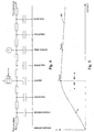
- Figure 4 is an illustration of thermal resistances and thermal capacitances of the wing section of Figure 3 .
- thermal resistances degree of thermal insulation
- thermal capacitances heat capacity
- heat flow corresponding to electrical current and temperatures corresponding to voltages.
- the heat generated by the heater mat is represented by a current source Q HEAT INPUT and the temperature sensor 314 of Figure 3 is represented as a voltage measurement.
- Each of the layers has an associated thermal capacity (which may be negligible) and the thermal resistance of each layer is also shown.
- the heat loss at the breeze surface (the interface with the air impinging on the wing), Q HEAT LOSS (BREEZE)
- Q HEAT LOSS INTERIOR
- the heat loss Q HEAT LOSS (INTERIOR) into the interior of the structure is considerably less than the heat loss Q HEAT LOSS (BREEZE) through the erosion shield (by design).
- Figure 5 is a graph illustrating the variation of temperature over distance within the wing section of Figure 3 .
- the temperature 502 is plotted from the left hand side 504, where large amounts of heat flow through the erosion shield, to the right hand side 506, where heat is slowly lost into the wing structure.
- the gradient of the curve 502 is equivalent to the thermal gradient (although not drawn to scale).
- the heater temperature T HEATER , the temperature sensor temperature T SENSOR and the erosion shield temperature T ES are indicated on the temperature curve 502.
- the temperature sensor temperature T SENSOR is approximately equal to the heater mat temperature T HEATER because of the shallow thermal gradient flowing into the structure 506.
- the erosion shield temperature T ES is quite different, however, because of the steep temperature gradient flowing out of the wing 504.
- the temperature T is substitutable for a voltage, and a corresponding current can be derived from the gradient of the curve 502.
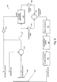
- Figure 6 is a schematic of a temperature control system for use with the ice protection system of Figure 1 .
- the control system 600 provides a heater output to a heater mat 602, and receives an input from the temperature probe 604, arranged proximate the heater mat as described above.
- the heater mat 602 is driven by a power control unit 606, which includes the appropriate power amplifiers and so on.
- the power control unit 606 is fed via a change rate limiter 608 and a magnitude limiter 610 that condition the power demand in order to avoid placing undue strain on the generator of the aircraft (or other structure, as applicable).
- the temperature of the surface to be protected can be calculated from knowledge of the heather mat thermal resistance and the thermal flux from the heater element (which can be derived from the power supplied to the heater element).
- the mat temperature is controlled through control of the power supplied to the mat.
- the power may either be controlled on the basis of the temperature sensor 604, directly, or through the derived surface temperature.
- the derived surface temperature is dependent on power, in addition to the temperature sensor value, it may be less stable in control. For this reason in the present embodiment it is chosen to control power on the basis of the output of the temperature sensor 604 at the rear of the mat.
- the switch 612 closes to form the control loop.
- the temperature probe input is subtracted from the input demand temperature by the processing unit 614 to determine an error signal.
- the error signal is then fed into a bounded integrator 616 and a proportional gain unit k 618.
- the output of the bounded integrator is fed through an integral gain k i 620.
- the proportional output and the integral output are summed by the processing unit 622, and fed into the power output chain via the magnitude limiter 610.
- the bounded integrator 616 is reset by the inverter 624 whenever the ice protection control system is switched off.
- Appropriate values of the parameters k and k i are selected in accordance with the principles of control theory in order to provide a control system that is stable and relatively responsive but which does not overshoot significantly.
- the control system 600 also includes other components such as analogue to digital converters, digital to analogue converters, power amplifiers, calibration filters, and so on which have been omitted for clarity.
- the control loop processing (in particular the PI controller element) is carried out by a digital signal processor (DSP), with the necessary transducers, power amplifiers and switching circuitry provided in hardware.
- DSP digital signal processor
- a derivative controller may also be provided (optionally in place of the proportional and/or integral elements), which can improve the responsiveness of the system to external disturbances. However it may be preferred to omit the derivative controller in order to minimise sensitivity to noise.
- the proportional and/or integral gains can be implemented using adaptive filters, to allow the system to be tuned to provide optimal responsiveness without significant overshoot.
- Figure 7 is a schematic of an alternative temperature control system for use with the ice protection system of Figure 1 .
- control system 700 provides a heater output to a heater mat 702, and receives an input from the temperature probe 704.
- the heater mat 702 is driven by a power control unit 706, which is fed via a change rate limiter 708 and a magnitude limiter 710.
- the switch 712 When the ice protection system is switched on (via the 'ice protection on' input), the switch 712 again closes to form the control loop, and the temperature probe input is subtracted from the input demand temperature by the processing unit 714 to determine an error signal.
- the error signal is then fed into a bounded integrator 716 and a proportional gain unit 718.
- the output of the bounded integrator is fed through an integral gain 720.
- the proportional output and the integral output are summed by the processing unit 722, and fed into the power output chain via the magnitude limiter 710.
- the ice protection enable signal is inverted by the inverter 724 to produce a first reset signal.
- the demand temperature and the measured temperature are compared by the processing unit 726 to determine whether or not the measured temperature exceeds the demand temperature by more than five degrees centigrade (or any other threshold that is desired to be set). If so, a second reset signal is generated.
- the two reset signals are fed into the OR gate 728, which has an output connected to the bounded integrator 716. If either reset signal is activated, the bounded integrator is reset. This can reduce the incidence of overshoot errors.
- Figure 8 is a graph illustrating the dependence of various temperature measurements on liquid water content (LWC).
- the LWC is one measure of the icing conditions that determines how much ice forms and therefore how much power is required to be supplied to remove the ice.
- the slat structure maximum temperature (approximately 140 °C) is shown on the graph, indicating the point beyond which delamination (structural failure) may be expected to occur.
- the requirement for ice protection is shown, indicating the erosion shield temperature that is required in order to avoid the formation of ice.
- a higher temperature is required in order to prevent ice formation.
- a minimum temperature for ice protection is indicated on the graph, corresponding to the temperature of the erosion shield that is necessary to prevent the formation of ice under the most extreme icing conditions (the highest LWC).
- the control system described above ensures that the average heater mat temperature is approximately constant, regardless of the icing conditions.
- the average heater mat temperature is chosen so that there is a suitably large margin of safety between the average heater mat temperature and the slat structure maximum temperature, but also so that the erosion shield temperature (also indicated on the graph) exceeds the minimum temperature required for ice protection by another appropriate safety margin. It can be seen (and is to be expected) that for a constant heater mat temperature, the erosion shield temperature drops with increasing LWC (because of the increasing thermal load on the system).
- the appropriate average heater mat temperature (the temperature demand of Figures 6 and 7 ) can be found by experiment and by consideration of the icing conditions likely to be faced for a particular aircraft.
- control system described above can supply more energy to the heater mats than may be required for a particular set of icing conditions, but it will also be appreciated that the control system is relatively simple and relatively stable, since it does not depend on any temperature measured at the erosion shield or otherwise distant from the heater mat (which can lead to instability because of the lag caused by thermal capacity between the heater mat and the temperature sensor). Additionally, the control system described above can lead to a relatively constant power demand from the ice protection system, which is in many cases preferable to a rapidly varying and relatively unpredictable power demand.
- Figure 9 is a graph illustrating a typical variation in heater mat temperature over distance. The temperature measured by the temperature sensor is plotted against a distance moved along the wing surface either above or below the stagnation zone of the wing (corresponding to the temperature measured by the sensor 314 of Figure 3 as it is moved up and down around the wing in the same plane as the cross-section of Figure 3 ).
- a heating mat on the leading edge of an aircraft wing is subject to both variable water impingement and variable flow rates over the surface. This means that the effective cooling coefficient is also variable. The cooling coefficient will tend to be lowest in the region of the flow stagnation zone. Normally the stagnation zone is heated with the highest power density. These two factors mean that the stagnation zone is usually always the hottest.
- An averaging temperature sensor can be constructed by using a point temperature sensor attached to a high thermal conductivity strip (such as a 2 inch length of copper, for example) in a low conductivity 'wrapper'.
- a point temperature sensor attached to a high thermal conductivity strip (such as a 2 inch length of copper, for example) in a low conductivity 'wrapper'.
- An alternative is to use a distributed or long resistive sensor. Currently the latter is preferred.
- the ice protection system of a large aircraft can be constructed from over 100 separate heater mats, and it can be cumbersome and expensive to provide a temperature sensor and a control system for each heater mat.
- the present embodiment addresses this issue by driving multiple heater mats from a single temperature sensor and control system, as will now be described with reference to Figures 10 to 13 .
- Figure 10 is a front-on view of the wing section of Figure 3 showing the placement of individual heater mats and a temperature sensor.
- the wing structure 1000 includes a first de-icing strip 1002, an anti-icing parting strip 1004 arranged approximately around the stagnation zone of the wing, and a second de-icing strip 1006.
- the de-icing strips 1002, 1006 are arranged so as to cover the areas of the wing where water run-back from the parting strip 1004 is likely to refreeze.
- the first de-icing strip 1002 comprises individual heater mats 1008, 1010, 1012, 1014, 1016.
- the parting strip 1004 comprises individual heater mats 1018, 1020, 1022, 1024, 1026.
- the second de-icing strip 1006 comprises individual heater mats 1028, 1030, 1032, 1034, 1036.
- a temperature sensor 1038 is provided behind the central mat 1022.
- all of the individual heater mats are driven from the single temperature sensor 1038.
- this can simplify construction and reduce cost.
- the thermal loading on the wing (and thus on each heater mat) not only varies with icing conditions but also with the position on the wing and the current flying conditions (angle of attack, wind speed, and so on).
- angle of attack, wind speed, and so on There are in fact many factors influencing the thermal load which cannot all effectively be measured and accounted for.
- another approach can be taken to address the varying thermal load, as will now be described.
- Figure 11 is an illustration of the nominal power of different anti-icing heater zones (with reference to the parting strip 1004 of Figure 10 ).
- the parting strip 1100 contains five separate heater mats.
- the nominal power of each of the heater zones that is required for effective anti-icing performance is determined during testing under a typical icing conditions (in a wind tunnel, for example). Some typical values of nominal power are illustrated in the figure.
- Figure 12 is an illustration of the ratios of the nominal powers of Figure 11 .
- the parting strip 1200 is again shown, and the relative power ratios of the anti-icing zones (relative to the central zone in which the temperature sensor is located) are shown.
- the power ratio can be defined as a more complicated function, for example varying in dependence on a measured property of the icing conditions, in order to more accurately model the relative power requirements under different conditions.
- Figure 13 is a schematic of a temperature control system for use with the heater zones of Figure 10 .
- the first heater mat 1302 is of the type shown in Figures 6 and 7 with an associated temperature probe 1308.
- the other heater mats 1304, 1306 are slave devices as discussed above (such as the heater mats 1020, 1024 of Figure 10 ).
- a master power control circuit 1310 is provided, of the type shown in Figures 6 or 7 (but excluding the power control 606, 706).
- the master control circuit 1310 takes the temperature probe 604 input, a demand temperature, and an ice protection enable signal as an input, and generates a power demand using proportional/integral (PI) control as described above.
- PI proportional/integral
- the heater mats are driven using a power control unit 1312, 1314, 1316 as before.
- the power demand of the slave mats 1304, 1306 are filtered through power demand multipliers 1318, 1320, which effectively multiply the power demand by the appropriate power ratio discussed above in relation to Figure 12 .
- control system can be scaled up as necessary and refinements to the control scheme can be made as discussed above.
- heater mats and associated temperature probes can also be embedded into the wing (or other) structure, or attached to the interior of a (hollow) wing structure. Normally external or embedded heater mats may be more suitable for composite material wing structures.
- the design can also be applied to metal structures, in which case external or interior heater mats may be more suitable.
- the design can of course be implemented for other structural materials and designs.
- ice protection system has been described above with particular reference to preventing ice build-up on the aerodynamic surfaces of an aircraft.
- the ice protection can find application in many other fields, including both mobile structures (including vehicles of various kinds) and static structures.
- the ice protection system could be use on land- or water-based vehicles (such as cars, buses, boats, and various military vehicles) as well as other air-based vehicles such as helicopters, spacecraft and the like.
- the system can also be used on buildings and other miscellaneous constructions including antennae and cabling, which may be particularly sensitive to a build-up of ice.
- ice formation may occur due to prevailing environmental conditions (cold climate and/or high winds) and/or because of the movement of a vehicle (creating high effective wind chill, for example).
- the ice protection system described above can also (where applicable) be adapted for use in any environment or application in which a surface or other part of a structure or the environment is required to be kept above a particular temperature (including situations in which no ice is present, for example to avoid condensation rather than ice formation).
- the system is suitable in particular in situations where a range of conditions prevail that cause a variable amount of heat loss in the structure or environment.
Landscapes
- Engineering & Computer Science (AREA)
- Aviation & Aerospace Engineering (AREA)
- Physics & Mathematics (AREA)
- General Physics & Mathematics (AREA)
- Automation & Control Theory (AREA)
- Control Of Resistance Heating (AREA)
- Gloves (AREA)
Claims (29)
- Système de commande de protection anti-glace (600, 700) pour une utilisation avec une structure comportant au moins une surface à protéger d'une plage de conditions de formation de glace, au moins un dispositif de chauffage, agencé en contact thermique avec ladite au moins une surface, et au moins un capteur de température pour délivrer au moins un signal de température, ledit au moins un capteur étant en contact thermique avec au moins un dit dispositif de chauffage, le système de commande de protection anti-glace comprenant :une première interface pour recevoir ledit au moins un signal de température dudit au moins un capteur de température (604, 704), le signal de température étant indicatif d'une température d'un ou de plusieurs dispositifs de chauffage (602, 702) ;une deuxième interface pour délivrer des signaux de commande de puissance pour commander ledit au moins un dispositif de chauffage (602, 702) ;un contrôleur (606, 706) configuré pour générer les signaux de commande de puissance pour commander la sortie de chaleur dudit au moins un dispositif de chauffage (602, 702) ; etune unité de traitement pour délivrer au moins une estimation de la température au niveau de ladite au moins une surface, l'unité de traitement calculant ladite au moins une estimation de la température en utilisant au moins une estimation de la chaleur délivrée par ledit au moins un dispositif de chauffage (602, 702), ledit au moins un signal de température, et au moins une estimation de la résistance thermique entre ledit au moins un dispositif de chauffage et ladite au moins une surface,dans lequel le contrôleur (606, 706) peut être utilisé pour générer les signaux de commande de puissance pour commander ledit au moins un dispositif de chauffage en utilisant ledit au moins un signal de température et/ou ladite au moins une estimation de la température au niveau de ladite au moins une surface, etdans lequel ledit contrôleur (606, 706) est configuré pour générer les signaux de commande de puissance pour commander la sortie de chaleur desdits un ou plusieurs dispositifs de chauffage (602, 702) en utilisant ledit au moins un signal de température pour maintenir la température du ou de chaque dispositif de chauffage à une température sensiblement constante.
- Système de commande de protection anti-glace (600, 700) selon la revendication 1, dans lequel ladite au moins une température sensiblement constante est suffisante pour éviter une accumulation de glace sur ladite au moins une surface dans les conditions de formation de glace les plus extrêmes auxquelles on s'attend à ce que l'avion soit exposé.
- Système de commande de protection anti-glace (600, 700) selon la revendication 1 ou 2, pouvant être utilisé pour maintenir la température de chaque dispositif de chauffage (602, 702) à une température sensiblement constante respective afin de permettre à différents dispositifs de chauffage de fonctionner à différentes températures.
- Système de commande de protection anti-glace (600, 700) selon l'une quelconque des revendications 1 à 3, pouvant être utilisé pour commander la sortie de chaleur dudit au moins un dispositif de chauffage (602, 702) pour maintenir une température au niveau de ladite au moins une surface à une température minimum ou plus.
- Système de commande de protection anti-glace (600, 700) selon l'une quelconque des revendications 1 à 4 pour une utilisation avec une structure dans laquelle ledit au moins un dispositif de chauffage (602, 702) comprend au moins une bande de rupture de glace, et dans lequel le contrôleur (606, 706) peut être utilisé pour mettre en marche et arrêter ladite au moins une bande de rupture de glace selon une planification de dégivrage.
- Système de commande de protection anti-glace (600, 700) selon l'une quelconque des revendications 1 à 5, comprenant en outre au moins un contrôleur de puissance (606, 706) pouvant être utilisé pour délivrer des quantités variables de puissance audit au moins un dispositif de chauffage (602, 702) conformément aux signaux de commande de puissance.
- Système de commande de protection anti-glace (600, 700) selon l'une quelconque des revendications 1 à 6, pouvant être utilisé pour recevoir un signal indicatif d'une température de dispositif de chauffage de demande, et pour maintenir la température dudit au moins un dispositif de chauffage (602, 702) conformément à la température de dispositif de chauffage de demande.
- Système de commande de protection anti-glace (600, 700) selon l'une quelconque des revendications 1 à 7, pouvant être utilisé pour déterminer une sortie de chaleur cible pour chaque dispositif de chauffage (602, 702), et pour commander ledit au moins un dispositif de chauffage en utilisant la sortie de chaleur cible.
- Système de commande de protection anti-glace (600, 700) selon la revendication 8 pour une utilisation avec une structure dans laquelle au moins un dit dispositif de chauffage (602, 702) a un capteur de température (604, 704) associé et au moins un dit dispositif de chauffage n'a pas de capteur de température associé, dans lequel le système de commande peut être utilisé pour déterminer la sortie de chaleur cible pour ledit au moins un dispositif de chauffage n'ayant pas de capteur de température associé en fonction de la sortie de chaleur cible d'un dispositif de chauffage ayant un capteur de température associé.
- Système de commande de protection anti-glace (600, 700) selon l'une quelconque des revendications 1 à 9, comprenant en outre au moins un contrôleur à rétroaction proportionnelle pour commander la sortie de chaleur de chaque dispositif de chauffage (602, 702) en utilisant ledit au moins un signal de température.
- Système de commande de protection anti-glace (600, 700) selon l'une quelconque des revendications 1 à 10, comprenant en outre au moins un contrôleur à anticipation pour commander la sortie de chaleur de chaque dispositif de chauffage (602, 702) en utilisant au moins un signal indicatif des conditions de formation de glace.
- Système de protection anti-glace pour une structure comportant au moins une surface à protéger d'une plage de conditions de formation de glace, le système de protection anti-glace comprenant :au moins un dispositif de chauffage (602, 702), pour un agencement en contact thermique avec ladite au moins une surface ;au moins un capteur de température (604, 704) pour délivrer au moins un signal de température, ledit au moins un capteur étant en contact thermique avec au moins un dit dispositif de chauffage (602, 702) ; etun système de commande de protection anti-glace (600, 700) selon l'une quelconque des revendications 1 à 11.
- Système de protection anti-glace selon la revendication 12, comportant une première résistance thermique entre ledit au moins un capteur de température (604, 704) et ledit au moins un dispositif de chauffage (602, 702) et une deuxième résistance thermique entre ledit au moins un capteur de température et au moins une surface à protéger, et dans lequel la première résistance thermique est inférieure à la deuxième résistance thermique.
- Système de protection anti-glace selon la revendication 12 ou 13, comportant une première capacité thermique entre ledit au moins un capteur de température (604, 704) et ledit au moins un dispositif de chauffage (602, 702) et une deuxième capacité thermique entre au moins une surface et ledit au moins un dispositif de chauffage à protéger, et dans lequel la première capacité thermique est inférieure à la deuxième capacité thermique.
- Système de protection anti-glace selon la revendication 12, 13 ou 14, dans lequel ledit au moins un dispositif de chauffage (602, 702) est agencé entre ledit au moins un capteur de température et au moins une surface à protéger.
- Système de protection anti-glace selon la revendication 15, ledit au moins un dispositif de chauffage (602, 702) étant agencé pour dissiper la chaleur dans une direction à travers au moins une surface à protéger et étant agencé pour dissiper la chaleur dans une autre direction à travers au moins un dissipateur de chaleur, ledit au moins un capteur de température (604, 704) étant agencé entre ledit au moins un dispositif de chauffage et ledit au moins un dissipateur de chaleur, et le système de protection anti-glace étant agencé de sorte qu'une première résistance thermique entre ledit au moins un dispositif de chauffage (602, 702) et ledit au moins un dissipateur de chaleur soit inférieure à une deuxième résistance thermique entre ledit au moins un dispositif de chauffage et ladite au moins une surface.
- Système de protection anti-glace selon la revendication 15 ou 16, dans lequel ledit au moins un capteur de température (604, 704) est séparé dudit au moins un dispositif de chauffage (602, 702) par une couche d'isolant thermique.
- Système de protection anti-glace selon l'une quelconque des revendications 12 à 17, dans lequel ledit au moins un capteur de température (604, 704) peut être utilisé pour fournir une lecture de température moyennée.
- Système de protection anti-glace selon la revendication 18, dans lequel ledit au moins un capteur de température (604, 704) comprend au moins un capteur de température ponctuel et au moins une bande de haute conductivité thermique à laquelle ledit au moins un capteur de température ponctuel est attaché.
- Système de protection anti-glace selon la revendication 18 ou 19, dans lequel ledit au moins un capteur de température (604, 704) comprend au moins un capteur de température résistif long ou réparti.
- Système de protection anti-glace selon l'une quelconque des revendications 12 à 20, dans lequel ledit au moins un dispositif de chauffage (602, 702) comprend au moins une bande anti-givrage.
- Avion comprenant un système de protection anti-glace selon l'une quelconque des revendications 12 à 21.
- Procédé de protection d'au moins une surface d'une structure d'une plage de conditions de formation de glace, la structure comprenant au moins un dispositif de chauffage (602, 702) en contact thermique avec ladite au moins une surface, et le procédé consistant à :recevoir au moins un signal de température d'au moins un capteur de température (604, 704) en contact thermique avec au moins un dit dispositif de chauffage (602, 702) ;calculer au moins une estimation de la température au niveau de ladite au moins une surface en utilisant au moins une estimation de la chaleur délivrée par ledit au moins un dispositif de chauffage (602, 702), ledit au moins un signal de température, et au moins une estimation de la résistance thermique entre ledit au moins un dispositif de chauffage et ladite au moins une surface ; etcommander la sortie de chaleur dudit au moins un dispositif de chauffage (602, 702) en utilisant ledit au moins un signal de température et/ou au moins une estimation de la température au niveau de ladite au moins une surface,dans lequel l'étape pour commander la sortie de chaleur dudit au moins un dispositif de chauffage consiste à commander la sortie de chaleur dudit au moins un dispositif de chauffage afin de maintenir la température du dispositif de chauffage ou de chaque dispositif de chauffage à une température sensiblement constante.
- Procédé d'installation d'un système de commande de protection anti-glace selon la revendication 1, consistant à :connecter une première interface du système de commande au dit au moins un capteur de température (604, 704), la première interface pouvant être utilisée pour recevoir des signaux de température dudit au moins un capteur de température,connecter une deuxième interface du système de commande, ladite deuxième interface pouvant être utilisée pour délivrer des signaux de commande de puissance pour commander ledit au moins un dispositif de chauffage (602, 702) ; etinstaller une unité de traitement pour délivrer au moins une estimation de la température au niveau de ladite au moins une surface, l'unité de traitement calculant ladite au moins une estimation de la température en utilisant au moins une estimation de la chaleur délivrée par ledit au moins un dispositif de chauffage (602, 702), ledit au moins un signal de température, et au moins une estimation de la résistance thermique entre ledit au moins un dispositif de chauffage et ladite au moins une surface ; etinstaller un contrôleur qui peut être utilisé pour générer le signal de commande de puissance pour commander les dispositifs de chauffage en utilisant ledit au moins un signal de température et/ou au moins une estimation de la température au niveau de ladite au moins une surface, et dans lequel le contrôleur est configuré pour générer les signaux de commande de puissance pour commander la sortie de chaleur dudit au moins un dispositif de chauffage en utilisant ledit au moins un signal de température et/ou au moins une estimation de la température au niveau de ladite au moins une surface, et dans lequel le contrôleur est configuré pour générer les signaux de commande de puissance pour commander la sortie de chaleur desdits un ou plusieurs dispositifs de chauffage (602, 702) pour maintenir la température du dispositif de chauffage ou de chaque dispositif de chauffage à une température sensiblement constante.
- Procédé d'installation d'un système de protection anti-glace selon la revendication 12, consistant à :agencer au moins un dispositif de chauffage (602, 702) en contact thermique avec ladite au moins une surface ;agencer au moins un capteur de température (604, 704) en contact thermique avec au moins un dit dispositif de chauffage (602, 702), ledit au moins un capteur de température pouvant être utilisé pour délivrer au moins un signal de température ; etinstaller un système de commande pour commander la sortie de chaleur dudit au moins un dispositif de chauffage, le système de commande comprenant un contrôleur (606, 706) configuré pour générer des signaux de commande de puissance pour commander la sortie de chaleur dudit au moins un dispositif de chauffage (602, 702) et une unité de traitement pour délivrer au moins une estimation de la température au niveau de ladite au moins une surface,dans lequel l'unité de traitement est configurée pour calculer ladite au moins une estimation de la température en utilisant au moins une estimation de la chaleur délivrée par ledit au moins un dispositif de chauffage (602, 702), ledit au moins un signal de température, et au moins une estimation de la résistance thermique entre ledit au moins un dispositif de chauffage et ladite au moins une surface, dans lequel le contrôleur (606, 706) peut être utilisé pour générer le signal de commande de puissance pour commander les dispositifs de chauffage en utilisant ledit au moins un signal de température et/ou au moins une estimation de la température au niveau de ladite au moins une surface, et dans lequel ledit contrôleur (606, 706) est configuré pour générer les signaux de commande de puissance pour commander la sortie de chaleur dudit au moins un dispositif de chauffage afin de maintenir la température dudit au moins un dispositif de chauffage à une température sensiblement constante.
- Structure pouvant être exposée à des conditions de formation de glace, comprenant :au moins un élément comportant au moins une surface à protéger d'une plage de conditions de formation de glace ; etun système de protection anti-glace selon l'une quelconque des revendications 12 à 21.
- Structure selon la revendication 26, dans laquelle ledit au moins un dispositif de chauffage est agencé à une position dans ledit élément éloignée de ladite au moins une surface.
- Structure selon la revendication 27 pour une utilisation en tant que structure d'avion, ledit au moins un élément comprenant au moins un bord d'attaque, et dans lequel ledit au moins un dispositif de chauffage est agencé éloigné dudit au moins un bord d'attaque, mais en contact thermique avec celui-ci.
- Structure selon l'une quelconque des revendications 26 à 28, dans laquelle la structure comprend un matériau stratifié.
Applications Claiming Priority (2)
| Application Number | Priority Date | Filing Date | Title |
|---|---|---|---|
| US78407906P | 2006-03-17 | 2006-03-17 | |
| PCT/GB2007/000966 WO2007107732A1 (fr) | 2006-03-17 | 2007-03-19 | Système de protection anti-glace |
Publications (2)
| Publication Number | Publication Date |
|---|---|
| EP2004488A1 EP2004488A1 (fr) | 2008-12-24 |
| EP2004488B1 true EP2004488B1 (fr) | 2012-04-25 |
Family
ID=38255305
Family Applications (1)
| Application Number | Title | Priority Date | Filing Date |
|---|---|---|---|
| EP07732059A Active EP2004488B1 (fr) | 2006-03-17 | 2007-03-19 | Système de protection anti-glace |
Country Status (5)
| Country | Link |
|---|---|
| US (1) | US8602359B2 (fr) |
| EP (1) | EP2004488B1 (fr) |
| AT (1) | ATE555016T1 (fr) |
| GB (1) | GB2450653B (fr) |
| WO (1) | WO2007107732A1 (fr) |
Families Citing this family (43)
| Publication number | Priority date | Publication date | Assignee | Title |
|---|---|---|---|---|
| US9581033B2 (en) * | 2007-02-06 | 2017-02-28 | United Technologies Corp0Ration | Surface mounted flexible heater for gas turbine engine application |
| US8049147B2 (en) | 2008-03-28 | 2011-11-01 | United Technologies Corporation | Engine inlet ice protection system with power control by zone |
| US7938368B2 (en) | 2008-04-07 | 2011-05-10 | United Technologies Corporation | Nosecone ice protection system for a gas turbine engine |
| US9656757B2 (en) | 2008-09-16 | 2017-05-23 | Hamilton Sundstrand Corporation | Propeller deicing system |
| DE102008051553A1 (de) * | 2008-10-14 | 2010-04-15 | Airbus Deutschland Gmbh | Heizsystem mit zumindest einer elektrothermischen Heizschicht, Strukturbauteil und Verfahren zum kontrollierten Beheizen des Heizsystems |
| BRPI0920243A2 (pt) | 2008-10-14 | 2019-09-24 | Airbus Operations Gmbh | sistema aquecedor com ao menos uma camada aquecedora eletrotérmica, componente estrutural com esta camada aquecedora, processo de aquecimento, bem como processo para produzir um produto semiacabado ou componente com um dispositivo aquecedor |
| US8037750B2 (en) * | 2009-10-29 | 2011-10-18 | Rosemount Aerospace, Inc. | Impending icing probe with thermal isolation pedestal |
| GB2479943B (en) | 2010-04-30 | 2015-03-11 | Ultra Electronics Ltd | Method of calibrating a heater system |
| US8560203B2 (en) * | 2010-07-30 | 2013-10-15 | Pratt & Whitney Canada Corp. | Aircraft engine control during icing of temperature probe |
| JP5582927B2 (ja) * | 2010-08-30 | 2014-09-03 | 三菱重工業株式会社 | 航空機の防除氷システム及びこれを備える航空機 |
| US8517601B2 (en) | 2010-09-10 | 2013-08-27 | Ultra Electronics Limited | Ice detection system and method |
| CN102455716B (zh) * | 2010-10-20 | 2013-12-18 | 技鼎股份有限公司 | 快速升降温装置及其温度控制方法 |
| US8727607B2 (en) | 2011-04-25 | 2014-05-20 | Ultra Electronics Limited | Method of calibrating a heater system |
| DE102011102804A1 (de) | 2011-05-30 | 2012-12-06 | Airbus Operations Gmbh | Bordgestütztes Enteisungssystem für Luftfahrzeuge sowie Enteisungsverfahren |
| US9221544B2 (en) | 2011-09-20 | 2015-12-29 | The Boeing Company | Integrated surface thermal management system |
| DE102012002132A1 (de) | 2012-02-03 | 2013-08-08 | Airbus Operations Gmbh | Vereisungsschutzsystem für ein Flugzeug und Verfahren zum Betreiben eines Vereisungsschutzsystems |
| US9359081B2 (en) * | 2012-06-12 | 2016-06-07 | The Boeing Company | Icing condition detection system |
| GB2509729B (en) * | 2013-01-11 | 2014-12-17 | Ultra Electronics Ltd | Apparatus and method for detecting water or ice |
| US10179652B2 (en) | 2013-07-29 | 2019-01-15 | Surewx Inc. | Active frost forecasting, detection and warning system and method |
| FR3013289B1 (fr) * | 2013-11-21 | 2015-12-25 | Valeo Systemes Dessuyage | Element chauffant pour balai d'essuie-glace d'un vehicule |
| US10167550B2 (en) | 2014-06-03 | 2019-01-01 | Aurora Flight Sciences Corporation | Multi-functional composite structures |
| US10368401B2 (en) * | 2014-06-03 | 2019-07-30 | Aurora Flight Sciences Corporation | Multi-functional composite structures |
| US10285219B2 (en) | 2014-09-25 | 2019-05-07 | Aurora Flight Sciences Corporation | Electrical curing of composite structures |
| EP3031726B1 (fr) | 2014-12-08 | 2016-11-02 | Zodiac Aerotechnics | Elément de voilure pour aéronef |
| US10543926B2 (en) * | 2015-12-21 | 2020-01-28 | Sikorsky Aircraft Corporation | Ice protection systems |
| US10189572B2 (en) * | 2016-05-02 | 2019-01-29 | The Boeing Company | Systems and methods for preventing ice formation on portions of an aircraft |
| US11168583B2 (en) | 2016-07-22 | 2021-11-09 | General Electric Company | Systems and methods for cooling components within a gas turbine engine |
| WO2019016601A2 (fr) | 2017-07-19 | 2019-01-24 | Nvent Services Gmbh | Élément de régulation de température pour antigivrage qui correspond aux caractéristiques de perte de chaleur d'un article en cours de régulation |
| US10256638B2 (en) | 2017-08-24 | 2019-04-09 | Ge Aviation Systems Llc | Method and system for operating a set of generators |
| GB2565842B (en) | 2017-08-25 | 2020-04-01 | Ge Aviat Systems Ltd | Method and apparatus for predicting conditions favorable for icing |
| RU2664972C1 (ru) * | 2017-09-25 | 2018-08-24 | Акционерное общество "Институт прикладной астрономии" (АО "ИПА") | Способ дистанционного определения условий обледенения воздушных судов на основе радиометрии реального времени |
| EP3704022B1 (fr) | 2017-10-30 | 2024-08-21 | Battelle Memorial Institute | Système de protection contre le givre et contrôleur |
| CN107560822B (zh) * | 2017-10-31 | 2020-05-05 | 中国商用飞机有限责任公司 | 发动机进气道前缘防冰冰风洞试验设备及其试验方法 |
| US11242152B2 (en) | 2017-11-17 | 2022-02-08 | Ge Aviation Systems Llc | Method and apparatus for detecting ice accretion |
| US10579080B2 (en) | 2018-04-06 | 2020-03-03 | Simmonds Precision Products, Inc. | Intelligent ice protection network |
| EP3738883A1 (fr) * | 2019-05-16 | 2020-11-18 | Airbus Operations, S.L.U. | Composant chauffé résistif d'aéronef et procédé de fabrication dudit composant d'aéronef |
| US11539316B2 (en) | 2019-07-30 | 2022-12-27 | General Electric Company | Active stability control of compression systems utilizing electric machines |
| GB2589368B (en) | 2019-11-29 | 2022-06-01 | Ultra Electronics Ltd | Apparatus and method for detecting water or ice |
| GB2594915B (en) | 2020-03-16 | 2022-10-26 | Ultra Electronics Ltd | Detecting delamination in a laminated structure |
| US11999493B2 (en) * | 2021-03-31 | 2024-06-04 | Goodrich Corporation | Method and system for ice shed |
| US12202610B2 (en) * | 2021-12-27 | 2025-01-21 | The Boeing Company | Ice protection system for an aircraft |
| CN114459149A (zh) * | 2021-12-28 | 2022-05-10 | 中国航天空气动力技术研究院 | 一种蓄热式风洞电预热加热器系统及控制方法 |
| GB2642825A (en) | 2024-07-19 | 2026-01-28 | Ultra Pcs Ltd | Structure comprising a heater layer and an erosion shield layer |
Family Cites Families (23)
| Publication number | Priority date | Publication date | Assignee | Title |
|---|---|---|---|---|
| US3440521A (en) * | 1967-01-23 | 1969-04-22 | Westinghouse Electric Corp | Temperature control means |
| DE2443224C3 (de) | 1974-09-10 | 1979-02-22 | Licentia Patent-Verwaltungs-Gmbh, 6000 Frankfurt | Verfahren zum Enteisen von Triebwerks-, Flügel- und Leitwerksystemen an Flugkörpern |
| US5206806A (en) * | 1989-01-10 | 1993-04-27 | Gerardi Joseph J | Smart skin ice detection and de-icing system |
| CA2074487C (fr) * | 1990-01-24 | 1995-06-27 | Otis H. Hastings | Stratifie conducteur utilise pour reguler la temperature de surfaces |
| EP0680878B1 (fr) | 1994-04-13 | 1999-12-22 | The B.F. Goodrich Company | Système électrothermique de dégivrage |
| US5657951A (en) | 1995-06-23 | 1997-08-19 | The B.F. Goodrich Company | Electrothermal de-icing system |
| US5921502A (en) * | 1996-06-19 | 1999-07-13 | Cox & Company, Inc. | Hybrid ice-protection system for use on roughness-sensitive airfoils |
| CA2227526A1 (fr) * | 1997-01-21 | 1998-07-21 | Michael J. Giamati | Systeme de degivrage hybride avec commande sequentielle d'element |
| US6145787A (en) | 1997-05-20 | 2000-11-14 | Thermion Systems International | Device and method for heating and deicing wind energy turbine blades |
| US6279856B1 (en) | 1997-09-22 | 2001-08-28 | Northcoast Technologies | Aircraft de-icing system |
| US6283411B1 (en) | 1998-01-21 | 2001-09-04 | The B.F. Goodrich Company | Hybrid deicer with element sequence control |
| US6027078A (en) * | 1998-02-27 | 2000-02-22 | The Boeing Company | Method and apparatus using localized heating for laminar flow |
| FR2779314B1 (fr) | 1998-05-27 | 2000-08-04 | Eurocopter France | Dispositif de chauffage a elements resistifs d'un profil aerodynamique |
| US6370450B1 (en) * | 1999-12-10 | 2002-04-09 | Rosemount Aerospace Inc. | Integrated total temperature probe system |
| US20030039298A1 (en) | 2001-08-22 | 2003-02-27 | Lear Corporation | System and method of vehicle climate control |
| US6753513B2 (en) | 2002-03-19 | 2004-06-22 | Hamilton Sundstrand | Propeller de-icing system |
| US6906537B2 (en) * | 2002-08-19 | 2005-06-14 | Hamilton Sundstrand | System for controlling the temperature of an aircraft airfoil component |
| US6913571B2 (en) | 2003-10-14 | 2005-07-05 | Datex-Ohmeda, Inc. | Direct heater control for infant care apparatus |
| FR2863586B1 (fr) * | 2003-12-12 | 2007-01-19 | Eurocopter France | Dispositif de degivrage/antigivrage modulaire d'une surface aerodynamique. |
| US7246773B2 (en) * | 2004-05-06 | 2007-07-24 | Goodrich Coporation | Low power, pulsed, electro-thermal ice protection system |
| US7784739B2 (en) * | 2004-05-26 | 2010-08-31 | The Boeing Company | Detection system and method for ice and other debris |
| CN101411243B (zh) * | 2004-06-10 | 2012-03-28 | 贝尔直升机泰克斯特龙公司 | 用于雷达屏蔽器的除冰系统 |
| DE102004042423A1 (de) * | 2004-09-02 | 2006-03-09 | Deutsches Zentrum für Luft- und Raumfahrt e.V. | Aerodynamisches Bauteil mit einer Flächenheizung und Verfahren zu seiner Herstellung |
-
2007
- 2007-03-19 EP EP07732059A patent/EP2004488B1/fr active Active
- 2007-03-19 WO PCT/GB2007/000966 patent/WO2007107732A1/fr not_active Ceased
- 2007-03-19 AT AT07732059T patent/ATE555016T1/de active
- 2007-03-19 GB GB0818912A patent/GB2450653B/en active Active
- 2007-03-19 US US12/293,405 patent/US8602359B2/en active Active
Also Published As
| Publication number | Publication date |
|---|---|
| GB2450653A (en) | 2008-12-31 |
| WO2007107732A1 (fr) | 2007-09-27 |
| US20090149997A1 (en) | 2009-06-11 |
| US8602359B2 (en) | 2013-12-10 |
| GB2450653B (en) | 2011-02-23 |
| EP2004488A1 (fr) | 2008-12-24 |
| ATE555016T1 (de) | 2012-05-15 |
| GB0818912D0 (en) | 2008-11-19 |
Similar Documents
| Publication | Publication Date | Title |
|---|---|---|
| EP2004488B1 (fr) | Système de protection anti-glace | |
| EP2428447B1 (fr) | Système et procédé de détection de glace | |
| EP2163475B1 (fr) | Système de dégivrage d'hélice | |
| EP3704022B1 (fr) | Système de protection contre le givre et contrôleur | |
| EP1968854B1 (fr) | Systeme de protection electro-thermique contre le givre a faible consommation d'energie | |
| US5496989A (en) | Windshield temperature control system | |
| GB2509729A (en) | Ice detection on an aircraft | |
| EP2383186A2 (fr) | Procédé d'étalonnage d'un système de chauffage | |
| EP4065470B1 (fr) | Appareil et procédé de détection d'eau ou de glace | |
| US8727607B2 (en) | Method of calibrating a heater system | |
| WO2001008973A1 (fr) | Procede et dispositif de degivrage par zones concu pour un avion | |
| CN101411243B (zh) | 用于雷达屏蔽器的除冰系统 | |
| US20240217664A1 (en) | Adjustable ice protection system parting strip | |
| EP3883337B1 (fr) | Configuration de dispositif chauffant à film mince pour sonde de données d'air | |
| EP3836747A1 (fr) | Éléments chauffants conformes à film mince pour capteurs d'angle d'attaque | |
| US20260116547A1 (en) | De-icing system control | |
| HK40042013A (en) | Apparatus and method for detecting water or ice |
Legal Events
| Date | Code | Title | Description |
|---|---|---|---|
| PUAI | Public reference made under article 153(3) epc to a published international application that has entered the european phase |
Free format text: ORIGINAL CODE: 0009012 |
|
| 17P | Request for examination filed |
Effective date: 20081016 |
|
| AK | Designated contracting states |
Kind code of ref document: A1 Designated state(s): AT BE BG CH CY CZ DE DK EE ES FI FR GB GR HU IE IS IT LI LT LU LV MC MT NL PL PT RO SE SI SK TR |
|
| 17Q | First examination report despatched |
Effective date: 20090710 |
|
| GRAP | Despatch of communication of intention to grant a patent |
Free format text: ORIGINAL CODE: EPIDOSNIGR1 |
|
| DAX | Request for extension of the european patent (deleted) | ||
| RBV | Designated contracting states (corrected) |
Designated state(s): AT BE BG CH CY CZ DE DK EE ES FI FR GR HU IE IS IT LI LT LU LV MC MT NL PL PT RO SE SI SK TR |
|
| GRAS | Grant fee paid |
Free format text: ORIGINAL CODE: EPIDOSNIGR3 |
|
| GRAA | (expected) grant |
Free format text: ORIGINAL CODE: 0009210 |
|
| AK | Designated contracting states |
Kind code of ref document: B1 Designated state(s): AT BE BG CH CY CZ DE DK EE ES FI FR GR HU IE IS IT LI LT LU LV MC MT NL PL PT RO SE SI SK TR |
|
| REG | Reference to a national code |
Ref country code: CH Ref legal event code: EP |
|
| REG | Reference to a national code |
Ref country code: AT Ref legal event code: REF Ref document number: 555016 Country of ref document: AT Kind code of ref document: T Effective date: 20120515 |
|
| REG | Reference to a national code |
Ref country code: IE Ref legal event code: FG4D |
|
| REG | Reference to a national code |
Ref country code: DE Ref legal event code: R096 Ref document number: 602007022247 Country of ref document: DE Effective date: 20120628 |
|
| REG | Reference to a national code |
Ref country code: NL Ref legal event code: VDEP Effective date: 20120425 |
|
| REG | Reference to a national code |
Ref country code: AT Ref legal event code: MK05 Ref document number: 555016 Country of ref document: AT Kind code of ref document: T Effective date: 20120425 |
|
| LTIE | Lt: invalidation of european patent or patent extension |
Effective date: 20120425 |
|
| PG25 | Lapsed in a contracting state [announced via postgrant information from national office to epo] |
Ref country code: LT Free format text: LAPSE BECAUSE OF FAILURE TO SUBMIT A TRANSLATION OF THE DESCRIPTION OR TO PAY THE FEE WITHIN THE PRESCRIBED TIME-LIMIT Effective date: 20120425 Ref country code: FI Free format text: LAPSE BECAUSE OF FAILURE TO SUBMIT A TRANSLATION OF THE DESCRIPTION OR TO PAY THE FEE WITHIN THE PRESCRIBED TIME-LIMIT Effective date: 20120425 Ref country code: CY Free format text: LAPSE BECAUSE OF FAILURE TO SUBMIT A TRANSLATION OF THE DESCRIPTION OR TO PAY THE FEE WITHIN THE PRESCRIBED TIME-LIMIT Effective date: 20120425 Ref country code: SE Free format text: LAPSE BECAUSE OF FAILURE TO SUBMIT A TRANSLATION OF THE DESCRIPTION OR TO PAY THE FEE WITHIN THE PRESCRIBED TIME-LIMIT Effective date: 20120425 Ref country code: PL Free format text: LAPSE BECAUSE OF FAILURE TO SUBMIT A TRANSLATION OF THE DESCRIPTION OR TO PAY THE FEE WITHIN THE PRESCRIBED TIME-LIMIT Effective date: 20120425 Ref country code: IS Free format text: LAPSE BECAUSE OF FAILURE TO SUBMIT A TRANSLATION OF THE DESCRIPTION OR TO PAY THE FEE WITHIN THE PRESCRIBED TIME-LIMIT Effective date: 20120825 |
|
| PG25 | Lapsed in a contracting state [announced via postgrant information from national office to epo] |
Ref country code: LV Free format text: LAPSE BECAUSE OF FAILURE TO SUBMIT A TRANSLATION OF THE DESCRIPTION OR TO PAY THE FEE WITHIN THE PRESCRIBED TIME-LIMIT Effective date: 20120425 Ref country code: SI Free format text: LAPSE BECAUSE OF FAILURE TO SUBMIT A TRANSLATION OF THE DESCRIPTION OR TO PAY THE FEE WITHIN THE PRESCRIBED TIME-LIMIT Effective date: 20120425 Ref country code: GR Free format text: LAPSE BECAUSE OF FAILURE TO SUBMIT A TRANSLATION OF THE DESCRIPTION OR TO PAY THE FEE WITHIN THE PRESCRIBED TIME-LIMIT Effective date: 20120726 Ref country code: PT Free format text: LAPSE BECAUSE OF FAILURE TO SUBMIT A TRANSLATION OF THE DESCRIPTION OR TO PAY THE FEE WITHIN THE PRESCRIBED TIME-LIMIT Effective date: 20120827 |
|
| PG25 | Lapsed in a contracting state [announced via postgrant information from national office to epo] |
Ref country code: BE Free format text: LAPSE BECAUSE OF FAILURE TO SUBMIT A TRANSLATION OF THE DESCRIPTION OR TO PAY THE FEE WITHIN THE PRESCRIBED TIME-LIMIT Effective date: 20120425 |
|
| PG25 | Lapsed in a contracting state [announced via postgrant information from national office to epo] |
Ref country code: EE Free format text: LAPSE BECAUSE OF FAILURE TO SUBMIT A TRANSLATION OF THE DESCRIPTION OR TO PAY THE FEE WITHIN THE PRESCRIBED TIME-LIMIT Effective date: 20120425 Ref country code: RO Free format text: LAPSE BECAUSE OF FAILURE TO SUBMIT A TRANSLATION OF THE DESCRIPTION OR TO PAY THE FEE WITHIN THE PRESCRIBED TIME-LIMIT Effective date: 20120425 Ref country code: SK Free format text: LAPSE BECAUSE OF FAILURE TO SUBMIT A TRANSLATION OF THE DESCRIPTION OR TO PAY THE FEE WITHIN THE PRESCRIBED TIME-LIMIT Effective date: 20120425 Ref country code: DK Free format text: LAPSE BECAUSE OF FAILURE TO SUBMIT A TRANSLATION OF THE DESCRIPTION OR TO PAY THE FEE WITHIN THE PRESCRIBED TIME-LIMIT Effective date: 20120425 Ref country code: CZ Free format text: LAPSE BECAUSE OF FAILURE TO SUBMIT A TRANSLATION OF THE DESCRIPTION OR TO PAY THE FEE WITHIN THE PRESCRIBED TIME-LIMIT Effective date: 20120425 Ref country code: NL Free format text: LAPSE BECAUSE OF FAILURE TO SUBMIT A TRANSLATION OF THE DESCRIPTION OR TO PAY THE FEE WITHIN THE PRESCRIBED TIME-LIMIT Effective date: 20120425 Ref country code: AT Free format text: LAPSE BECAUSE OF FAILURE TO SUBMIT A TRANSLATION OF THE DESCRIPTION OR TO PAY THE FEE WITHIN THE PRESCRIBED TIME-LIMIT Effective date: 20120425 |
|
| PG25 | Lapsed in a contracting state [announced via postgrant information from national office to epo] |
Ref country code: IT Free format text: LAPSE BECAUSE OF FAILURE TO SUBMIT A TRANSLATION OF THE DESCRIPTION OR TO PAY THE FEE WITHIN THE PRESCRIBED TIME-LIMIT Effective date: 20120425 |
|
| PLBE | No opposition filed within time limit |
Free format text: ORIGINAL CODE: 0009261 |
|
| STAA | Information on the status of an ep patent application or granted ep patent |
Free format text: STATUS: NO OPPOSITION FILED WITHIN TIME LIMIT |
|
| 26N | No opposition filed |
Effective date: 20130128 |
|
| PG25 | Lapsed in a contracting state [announced via postgrant information from national office to epo] |
Ref country code: ES Free format text: LAPSE BECAUSE OF FAILURE TO SUBMIT A TRANSLATION OF THE DESCRIPTION OR TO PAY THE FEE WITHIN THE PRESCRIBED TIME-LIMIT Effective date: 20120805 |
|
| REG | Reference to a national code |
Ref country code: DE Ref legal event code: R097 Ref document number: 602007022247 Country of ref document: DE Effective date: 20130128 |
|
| PG25 | Lapsed in a contracting state [announced via postgrant information from national office to epo] |
Ref country code: BG Free format text: LAPSE BECAUSE OF FAILURE TO SUBMIT A TRANSLATION OF THE DESCRIPTION OR TO PAY THE FEE WITHIN THE PRESCRIBED TIME-LIMIT Effective date: 20120725 |
|
| PG25 | Lapsed in a contracting state [announced via postgrant information from national office to epo] |
Ref country code: MC Free format text: LAPSE BECAUSE OF NON-PAYMENT OF DUE FEES Effective date: 20130331 |
|
| REG | Reference to a national code |
Ref country code: CH Ref legal event code: PL |
|
| REG | Reference to a national code |
Ref country code: IE Ref legal event code: MM4A |
|
| PG25 | Lapsed in a contracting state [announced via postgrant information from national office to epo] |
Ref country code: CH Free format text: LAPSE BECAUSE OF NON-PAYMENT OF DUE FEES Effective date: 20130331 Ref country code: LI Free format text: LAPSE BECAUSE OF NON-PAYMENT OF DUE FEES Effective date: 20130331 Ref country code: IE Free format text: LAPSE BECAUSE OF NON-PAYMENT OF DUE FEES Effective date: 20130319 |
|
| PG25 | Lapsed in a contracting state [announced via postgrant information from national office to epo] |
Ref country code: MT Free format text: LAPSE BECAUSE OF FAILURE TO SUBMIT A TRANSLATION OF THE DESCRIPTION OR TO PAY THE FEE WITHIN THE PRESCRIBED TIME-LIMIT Effective date: 20120425 |
|
| PG25 | Lapsed in a contracting state [announced via postgrant information from national office to epo] |
Ref country code: TR Free format text: LAPSE BECAUSE OF FAILURE TO SUBMIT A TRANSLATION OF THE DESCRIPTION OR TO PAY THE FEE WITHIN THE PRESCRIBED TIME-LIMIT Effective date: 20120425 |
|
| PG25 | Lapsed in a contracting state [announced via postgrant information from national office to epo] |
Ref country code: LU Free format text: LAPSE BECAUSE OF NON-PAYMENT OF DUE FEES Effective date: 20130319 Ref country code: HU Free format text: LAPSE BECAUSE OF FAILURE TO SUBMIT A TRANSLATION OF THE DESCRIPTION OR TO PAY THE FEE WITHIN THE PRESCRIBED TIME-LIMIT; INVALID AB INITIO Effective date: 20070319 |
|
| REG | Reference to a national code |
Ref country code: FR Ref legal event code: PLFP Year of fee payment: 10 |
|
| REG | Reference to a national code |
Ref country code: FR Ref legal event code: PLFP Year of fee payment: 11 |
|
| REG | Reference to a national code |
Ref country code: FR Ref legal event code: PLFP Year of fee payment: 12 |
|
| REG | Reference to a national code |
Ref country code: DE Ref legal event code: R081 Ref document number: 602007022247 Country of ref document: DE Owner name: ULTRA PCS LTD., CHELTENHAM, GB Free format text: FORMER OWNER: ULTRA ELECTRONICS LTD., GREENFORD, GB |
|
| PGFP | Annual fee paid to national office [announced via postgrant information from national office to epo] |
Ref country code: FR Payment date: 20251231 Year of fee payment: 20 |
|
| PGFP | Annual fee paid to national office [announced via postgrant information from national office to epo] |
Ref country code: DE Payment date: 20260102 Year of fee payment: 20 |