EP2004560B1 - Verfahren und vorrichtung zur herstellung eines verbundstrangs - Google Patents
Verfahren und vorrichtung zur herstellung eines verbundstrangs Download PDFInfo
- Publication number
- EP2004560B1 EP2004560B1 EP07731804A EP07731804A EP2004560B1 EP 2004560 B1 EP2004560 B1 EP 2004560B1 EP 07731804 A EP07731804 A EP 07731804A EP 07731804 A EP07731804 A EP 07731804A EP 2004560 B1 EP2004560 B1 EP 2004560B1
- Authority
- EP
- European Patent Office
- Prior art keywords
- filaments
- thermoplastic
- glass
- drum
- speed
- Prior art date
- Legal status (The legal status is an assumption and is not a legal conclusion. Google has not performed a legal analysis and makes no representation as to the accuracy of the status listed.)
- Not-in-force
Links
- 239000002131 composite material Substances 0.000 title claims abstract description 56
- 238000000034 method Methods 0.000 title claims abstract description 17
- 238000004519 manufacturing process Methods 0.000 title claims description 14
- 229920001169 thermoplastic Polymers 0.000 claims abstract description 99
- 239000004416 thermosoftening plastic Substances 0.000 claims abstract description 99
- 239000011521 glass Substances 0.000 claims abstract description 78
- 238000002156 mixing Methods 0.000 claims abstract description 18
- 238000009987 spinning Methods 0.000 claims abstract description 18
- 238000010438 heat treatment Methods 0.000 claims abstract description 10
- 239000011248 coating agent Substances 0.000 claims abstract description 9
- 238000000576 coating method Methods 0.000 claims abstract description 9
- 230000035515 penetration Effects 0.000 claims abstract 3
- 239000011368 organic material Substances 0.000 claims description 8
- 239000005416 organic matter Substances 0.000 abstract 2
- 238000009434 installation Methods 0.000 description 9
- 239000012815 thermoplastic material Substances 0.000 description 8
- 238000004804 winding Methods 0.000 description 6
- 239000004952 Polyamide Substances 0.000 description 5
- 238000001816 cooling Methods 0.000 description 5
- 239000006060 molten glass Substances 0.000 description 5
- 229920002647 polyamide Polymers 0.000 description 5
- 229920000139 polyethylene terephthalate Polymers 0.000 description 5
- 239000005020 polyethylene terephthalate Substances 0.000 description 5
- XLYOFNOQVPJJNP-UHFFFAOYSA-N water Substances O XLYOFNOQVPJJNP-UHFFFAOYSA-N 0.000 description 5
- 241001639412 Verres Species 0.000 description 4
- -1 polyethylene terephthalate Polymers 0.000 description 4
- 238000009826 distribution Methods 0.000 description 3
- 238000001035 drying Methods 0.000 description 3
- 230000000694 effects Effects 0.000 description 3
- 239000012530 fluid Substances 0.000 description 3
- 238000012423 maintenance Methods 0.000 description 3
- 239000000243 solution Substances 0.000 description 3
- 241001417494 Sciaenidae Species 0.000 description 2
- 150000001875 compounds Chemical class 0.000 description 2
- 230000003750 conditioning effect Effects 0.000 description 2
- 238000002788 crimping Methods 0.000 description 2
- 229920001707 polybutylene terephthalate Polymers 0.000 description 2
- 239000007921 spray Substances 0.000 description 2
- 238000005507 spraying Methods 0.000 description 2
- 238000011144 upstream manufacturing Methods 0.000 description 2
- OKTJSMMVPCPJKN-UHFFFAOYSA-N Carbon Chemical compound [C] OKTJSMMVPCPJKN-UHFFFAOYSA-N 0.000 description 1
- 229920000571 Nylon 11 Polymers 0.000 description 1
- 229920000299 Nylon 12 Polymers 0.000 description 1
- 229920002292 Nylon 6 Polymers 0.000 description 1
- 229920002302 Nylon 6,6 Polymers 0.000 description 1
- 229910000629 Rh alloy Inorganic materials 0.000 description 1
- 238000005299 abrasion Methods 0.000 description 1
- 230000001133 acceleration Effects 0.000 description 1
- 229910052799 carbon Inorganic materials 0.000 description 1
- 230000002301 combined effect Effects 0.000 description 1
- 238000000151 deposition Methods 0.000 description 1
- 230000003292 diminished effect Effects 0.000 description 1
- 238000001125 extrusion Methods 0.000 description 1
- 239000004744 fabric Substances 0.000 description 1
- 239000007789 gas Substances 0.000 description 1
- 239000008187 granular material Substances 0.000 description 1
- 229910002804 graphite Inorganic materials 0.000 description 1
- 239000010439 graphite Substances 0.000 description 1
- 230000005484 gravity Effects 0.000 description 1
- 238000010348 incorporation Methods 0.000 description 1
- 238000002347 injection Methods 0.000 description 1
- 239000007924 injection Substances 0.000 description 1
- 238000005304 joining Methods 0.000 description 1
- 239000007788 liquid Substances 0.000 description 1
- 239000000203 mixture Substances 0.000 description 1
- 238000012986 modification Methods 0.000 description 1
- 230000004048 modification Effects 0.000 description 1
- PXXKQOPKNFECSZ-UHFFFAOYSA-N platinum rhodium Chemical compound [Rh].[Pt] PXXKQOPKNFECSZ-UHFFFAOYSA-N 0.000 description 1
- 229920000728 polyester Polymers 0.000 description 1
- 229920000642 polymer Polymers 0.000 description 1
- 229920002635 polyurethane Polymers 0.000 description 1
- 239000004814 polyurethane Substances 0.000 description 1
- 230000002787 reinforcement Effects 0.000 description 1
- 239000012779 reinforcing material Substances 0.000 description 1
- 238000000926 separation method Methods 0.000 description 1
- 238000004513 sizing Methods 0.000 description 1
- 239000007787 solid Substances 0.000 description 1
- 229920002994 synthetic fiber Polymers 0.000 description 1
- 239000012209 synthetic fiber Substances 0.000 description 1
Images

Classifications
-
- C—CHEMISTRY; METALLURGY
- C03—GLASS; MINERAL OR SLAG WOOL
- C03B—MANUFACTURE, SHAPING, OR SUPPLEMENTARY PROCESSES
- C03B37/00—Manufacture or treatment of flakes, fibres, or filaments from softened glass, minerals, or slags
-
- D—TEXTILES; PAPER
- D01—NATURAL OR MAN-MADE THREADS OR FIBRES; SPINNING
- D01D—MECHANICAL METHODS OR APPARATUS IN THE MANUFACTURE OF ARTIFICIAL FILAMENTS, THREADS, FIBRES, BRISTLES OR RIBBONS
- D01D5/00—Formation of filaments, threads, or the like
- D01D5/08—Melt spinning methods
-
- D—TEXTILES; PAPER
- D01—NATURAL OR MAN-MADE THREADS OR FIBRES; SPINNING
- D01D—MECHANICAL METHODS OR APPARATUS IN THE MANUFACTURE OF ARTIFICIAL FILAMENTS, THREADS, FIBRES, BRISTLES OR RIBBONS
- D01D10/00—Physical treatment of artificial filaments or the like during manufacture, i.e. during a continuous production process before the filaments have been collected
- D01D10/02—Heat treatment
Definitions
- the invention relates to a method and a device for manufacturing a composite yarn formed by the combination of a multiplicity of continuous filaments of glass and continuous filaments of high shrinkage thermoplastic organic material.
- EP-A-0 367 661 which describes a method using a first installation comprising a die containing molten glass from which continuous glass filaments are drawn, and a second installation comprising a spinning head, fed under pressure by an organic material thermoplastic which delivers continuous filaments.
- the two types of filaments are assembled into at least one composite yarn and during assembly the filaments can be in the form of webs, or web and son.
- the filaments or the glass yarn are surrounded by thermoplastic filaments which protect the glass from friction on the solid surfaces with which the yarn is in contact.
- thermoplastic filaments make it possible to improve the resistance of the yarn to abrasion, it also introduces tensions in the yarn due to a phenomenon of shrinkage of said filaments, which causes a ripple of the glass filaments.
- the presence of corrugation is particularly visible when the composite wire is wound in the form of a coil because it is deformed over its entire periphery.
- the phenomenon of shrinkage has several disadvantages: it requires the use of thick cuffs for the realization of the coils so that they can withstand the hooping exerted by the composite yarn and disrupts the unwinding of the wire from the coil because it it does not have the ideal geometric characteristics that are required for the intended application. Moreover, such a yarn is not advantageous for producing a fabric that can be used as reinforcing material for large flat parts because, because of the corrugations, the filaments are not perfectly aligned in the final composite. The reinforcement capacity of the yarns in a given direction is thereby diminished.
- EP-A-0 505 275 a process for producing a composite yarn similar to that previously described in EP-A-0 367 661 which provides for forming the thermoplastic filaments by means of a spinning head usually used in the field of the synthetic fiber industry. In this way, it is possible to obtain a composite yarn formed of one or more glass yarns surrounded by organic filaments, which is independent of the configuration of the spinning head used for the extrusion of the organic filaments.
- thermoplastic filaments with the glass filaments with a co-mixing speed which is greater than the drawing speed of the glass filaments.
- the speed difference is determined so that the shrinkage phenomenon compensates for the excess initial length of the thermoplastic filaments with respect to the glass filaments.
- thermoplastic filaments pass over a variable speed, drum-type stretch stretcher that accentuates the excess length, resulting in a composite yarn having linear glass filaments and thermoplastic filaments. are wavy.
- thermoplastic composite yarn which comprises mixing a web of thermoplastic filaments with a bundle or a ply of glass filaments, the thermoplastic filaments being heated upstream of the convergence point at a temperature above their relaxation temperature, stretched and then cooled.
- the composite yarn obtained is ripple-free and stable over time.
- the direct manufacture of rovings (“rovings" in English), without passing through an intermediate step of unwinding the cake and winding the wire, is operated continuously by drawing the composite wire under the die at a speed compatible with the stretching of the glass filaments. At this already important speed (of the order of a few meters to ten meters per second) is associated a drawing speed of the thermoplastic filaments upstream of the point of convergence which is even higher.
- thermoplastics which undergo a limited shrinkage.
- shrinkage As the shrinkage is greater, the stretcher becomes inoperative because its speed can no longer be increased so as to sufficiently increase the length of the thermoplastic filaments so that the composite yarn does not show any waviness.
- the object of the present invention is to provide a process for the manufacture of a composite yarn comprising continuous filaments of high shrinkage thermoplastic material and co-mixed continuous glass filaments which exhibit no undulation during its manufacture and which remains stable. in time.
- thermoplastic filaments derived from a spinning head, said thermoplastic filaments being mixed in the form of a sheet with a bundle or a sheet of the glass filaments, in which, before being co-mixed with the glass filaments, the thermoplastic filaments are stretched , heated and then projected on a moving support with a speed during their projection on the support which is greater than the speed of travel of said support.
- the combined effect of the stretching and spraying of the heated thermoplastic filaments provides them with a high level of crimp which subsequently makes it possible to compensate for the shrinkage of the thermoplastic material in the composite yarn.
- thermoplastic filaments are carried out simultaneously.
- thermoplastic filaments are guided in the form of a sheet to the glass filaments, also in the form of a sheet, and are associated with them at identical speeds between the coating roll and the collection point of all the filaments into a composite yarn.
- thermoplastic filaments are projected onto the glass filaments deposited on the moving support, in the running direction of said support. A ply formed by the entanglement of the crimped thermoplastic filaments with the linear glass filaments is thus obtained, this ply being subsequently gathered together to form the composite yarn.
- the method according to the invention makes it possible to obtain a composite yarn without any undulation: the glass filaments which enter into the constitution of the composite yarn are linear immediately after their gathering with the thermoplastic filaments, and they retain their linearity after the collection in form winding. Finally, the thermoplastic filaments in the composite yarn can be linear or corrugated according to the level of crimp that was initially conferred on them.
- the invention it is possible to form coils under the usual conditions for producing glass yarns, in particular by using cuffs of ordinary thickness given the absence of hooping of the composite yarn, these cuffs being removable for obtain balls and reused if necessary.
- This has the advantage of being able to extract the composite yarn according to the principle of unwinding (from the outside) or scrolling (from the inside).
- the method according to the invention ensures a homogeneous distribution and a high co-blending of the filaments within the composite yarn.
- the invention also proposes a device according to claim 6 allowing the implementation of this method.
- this device comprises on the one hand an installation comprising at least one die fed with molten glass, whose lower face comprises a multitude of orifices, this die being associated with a coating device, and secondly an installation comprising at least one spinning head fed with molten thermoplastic organic material, the lower face of which is provided with a multiplicity of orifices, this spinning head being associated with drum-type stretcher, thermoplastic filament spraying device with heating means, drum-type moving support, and means for mixing thermoplastic filaments with glass filaments, and common means the two installations for assembling and winding the composite wire.
- the drum stretcher has at least two rollers operating at varying speeds, preferably providing an increasing linear velocity of the thermoplastic filaments.
- the stretcher may be provided with heating means, for example electrical or infra-red, preferably placed in the first drum encountered by the thermoplastic filaments in order to preheat them and thus promote their stretching.
- the means for projecting the thermoplastic filaments onto the moving support is a device implementing the properties of the fluids which may be liquids or gases such as air, pulsed or compressed.
- the fluids which may be liquids or gases such as air, pulsed or compressed.
- it is a Venturi system whose role is only to project the thermoplastic filaments by giving them an orientation and an adequate spatial distribution, without giving them additional speed.
- the heating means in particular electrical means, are associated with the device for projecting the thermoplastic filaments.
- the heating of the thermoplastic filaments to a temperature close to their softening temperature is performed in a homogeneous and rapid manner, which makes it possible to obtain a satisfactory crimp state during the projection on the moving support.
- the moving support may consist of a drum whose surface has perforations, comprising a separating member of the internal volume into at least two compartments, one connected to means for maintaining it in depression, the other associated means for putting it in overpressure.
- the size and arrangement of the compartments are chosen so as to keep the thermoplastic filaments in their initial state of crimp, in the form of a sheet at the drum surface located above the first compartment, and to obtain the separation of the sheet when it passes over the second compartment.
- the means for mixing the two types of filaments can be constituted by a Venturi system as described above which makes it possible to project the thermoplastic filaments into a sheet or bundle of glass filaments.
- this system projects the thermoplastic filaments at a speed identical to the drawing speed of the glass filaments.
- the means ensuring the co-mingling of the filaments may also be constituted by the drum-type moving support.
- the drum serves as a support for the sheet of glass filaments, which wraps around it, and the crimped thermoplastic filaments in the form of a sheet mingle with the glass filaments on a generatrix of the drum.
- the devices described above allow the production of composite yarns, from pre-curled high-shrink thermoplastic filaments and glass filaments, which exhibit no further deformation, that is to say which remain stable over time.
- Such devices are applicable to any type of known glass, for example glass E, R, S, AR or C, glass E being preferred.
- thermoplastic material which may exhibit a high shrinkage
- a polymer belonging to the group of polyurethanes polyesters such as polyethylene terephthalate (PET) and polybutylene terephthalate (PBT), and polyamides.
- PET polyethylene terephthalate
- PBT polybutylene terephthalate
- polyamides such as polyamide-6, polyamide-6,6, polyamide-11 and polyamide-12.
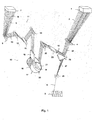
- FIG 1 On the figure 1 is shown a schematic view of a complete installation according to the invention. It comprises a die 1 supplied with molten glass or a hopper containing cold glass, for example in the form of balls that fall by simple gravity, or from the front of a furnace which directly conveys the glass to its summit ,.
- a die 1 supplied with molten glass or a hopper containing cold glass, for example in the form of balls that fall by simple gravity, or from the front of a furnace which directly conveys the glass to its summit ,.
- the die 1 is usually made of platinum-rhodium alloy and is heated by Joule effect so as to remelt the glass or maintain it at a high temperature. From die 1 flows a multitude of molten glass threads which are drawn in the form of a bundle 2 of filaments by a device, not shown, also forming the coil 3. On the beam path 2 is arranged a coating roll 4, for example made of graphite, which deposits on the glass filaments a size intended to prevent or limit the friction of the filaments on the members with which they come into contact. The size may be aqueous or anhydrous (i.e., less than 5% by weight water) and contain compounds - or derivatives thereof - which form part of the thermoplastic filaments 5 associate with the glass filaments to form the composite yarn 6.
- FIG. 1 On the figure 1 is also shown schematically a spinning head 7 from which are extruded the thermoplastic filaments 5.
- the spinning head 7 is fed with a molten thermoplastic material, high shrinkage, for example from an extruder, not shown, fed by granules, which flows under pressure through multiple orifices under the spinning head 7, to form the filaments 5 by stretching and cooling.
- the cooling of the filaments is carried out by forced convection, by means of a conditioning device 8 of shape adapted to the spinning head 7 and which generates a flow of laminar air perpendicular to the filaments.
- the cooling air has a flow rate, a temperature and a hygrometry that are kept constant.
- the filaments 5 then pass over a roller 9 which allows them to be gathered in the form of a web 10, on the one hand, and to deviate their trajectory, on the other hand.
- thermoplastic filaments After passing on the roll 9, the ply 10 of thermoplastic filaments passes over a stretcher 11 formed for example rollers 12, 13 which can rotate at the same speed or have different speeds from so that the acceleration is in the direction of scrolling thermoplastic filaments.
- the drawstring 11 has the function of stretching the filaments 5 and conferring a determined speed on the web 10. It is possible to vary the rotational speed of the rollers 12 and 13 so as to precisely adjust the projection speed of the filaments thermoplastics on the drum 17.
- a heating system for example electric, which ensures a fast and homogeneous preheating of the thermoplastic filaments by contact with the surface of the rollers .
- the stretcher 11 may be formed of a larger number of rollers, preferably operating in pairs, for example four or six rolls.
- the sheet 10 of thermoplastic filaments, possibly preheated, is then directed towards the deflection roller 14, which can be heated and possibly be motor, then it passes into a crimping device 15 formed for example of a Venturi system 16 and a drum 17.
- the Venturi system 16 makes it possible to maintain the individualized thermoplastic filaments and to project them into a regular ply of appropriate size on the drum 17.
- the Venturi system 16 operates with a supply of compressed air and does not communicate additional speed to the ply 10.
- This system is associated with a heating device (not shown), for example by means of a fluid such as hot air or steam, and has the role of bringing the thermoplastic filaments to a temperature close to the temperature softening the thermoplastic material to improve their curability.
- the ply 10 of thermoplastic filaments is projected onto the drum 17.
- the rotation speed of the drum 17 is less than the speed of the ply 10 during its projection so that the filaments curl as soon as they come into contact with the surface of said drum.
- the drum 17 is provided with a central groove 18, slightly smaller than the width of the drum, which is pierced with multiple orifices (not shown). It also comprises an element 19, coaxial, non-movable relative to the drum, which serves to separate the interior of the drum into two compartments 20, 21.
- the compartment 20 is connected to a device, not shown, which allows to put it in depression, for example a pump suction, and the compartment 21 is connected to a device, not shown, for putting it in overpressure, for example an air injection device.
- the ply 10 of crimped filaments is held in the groove 18 at the depression chamber 20 and is cooled, by simple contact with the perforated surface or via a fluid, by example of water or a primer composition sprayed on the filaments. Then, the web 10 separates from the surface of the drum 17 at the compartment 21 under the effect of pressurized air passing through the perforations.
- the web 10 then passes over a deflection roller 22, then into a Venturi device 23 which holds the crimped thermoplastic filaments in individualized form until they are mixed with the glass filaments of the web 24.
- thermoplastic filaments arrive with a speed equal to that of the glass filaments.
- a deflector 26 provided with a notch ensures the maintenance, in particular on the edges, of all the filaments and makes it possible to attenuate the perturbation experienced by the sheet 24 of glass filaments at the time of the projection of the sheet 10 of curly thermoplastic filaments.
- the sheet 27 of crimped thermoplastic filaments and intertwined glass filaments then passes over the device 25 which allows the filaments to be assembled into a composite yarn 6, which is immediately wound in the form of a reel 3 by means of a device of FIG. stretching, not shown, which operates at a given linear velocity kept constant to ensure the desired linear density.
- This linear speed which allows the drawing of the glass filaments is generally equal to that which the drum 17 communicates to the ply 10 of crimped thermoplastic filaments. Nevertheless, it is possible to mix the thermoplastic filaments with the glass filaments with a speed during their projection which can be lower in order to confer additional tension thermoplastic filaments to improve their maintenance in sheet until the point of co-blending with the glass filaments. In these circumstances, the difference between the speed of projection of the thermoplastic filaments and the drawing speed of the glass filaments does not exceed 10%.
- the figure 2 represents an installation according to a second embodiment of the invention.
- the devices and means in common bear the same numbers as on the figure 1 .
- the bundle 2 of glass filaments flowing from the die is drawn by a device (not shown) which forms the coil 3.
- the bundle 2 passes over the coating roll 4 which deposits a size on the glass filaments and the sheet 24 formed is wound on the drum 17.
- thermoplastic filaments 5 extruded from the spinning head 7, cooled by the conditioning device 8, are gathered in a web 10 at the roller 9.
- the web 10 then passes over the roller stretcher 11, 12, 13 and is stretched under the same conditions as at the figure 1 .
- the sheet 10 is directed towards the roll 14, possibly heated and / or motor, and in the crimping device 15 formed by the Venturi system 16 and the drum 17.
- thermoplastic filaments of the web 10 are maintained in the individualized state and are heated to a temperature close to the softening temperature to help achieve a high crimp level.
- the heated web 10 is projected onto the drum 17 which rotates at a speed lower than the projection speed of the filaments which makes them curl.
- the junction of the ply 10 of crimped thermoplastic filaments and the ply 24 of glass filaments is on a generatrix of the drum 17.
- the projection of the ply 10 takes place while the filaments of the ply 24 are contained in the groove 18 drum 17; this way of proceeding avoids disturbing the sheet of glass filaments and thus reduces the risk of breakage of said filaments.
- thermoplastic filaments and glass filaments wound on the drum 17 arrives at the compartment 21, it detaches from the surface when it arrives at the compartment 21 under the action of pressurized air under the effect of the air pressure coming from the interior of said compartment.
- the web 27 passes over the roll 22 and the filament collecting device 25 into a composite yarn 6 which is wound into the form of the reel 3.
- a second device 25 may be disposed between the exit of the drum 17 and the roll 22 to contribute to a better gathering of the composite yarn.
- the coils obtained using the process according to the invention consist of a composite yarn whose glass filaments are linear and the thermoplastic filaments are curled (or corrugated) permanently and stable over time.
- the level of crimp or corrugation of the thermoplastic filaments in the composite yarn depends on the amount of crimp that has been given to them during the projection on the moving support.
- the distribution of glass filaments and thermoplastic filaments within the composite yarn is homogeneous, reflecting good co-mingling of the filaments.
- the coating device comprises separate rollers, each of them depositing on the glass filaments one of the sizing solutions. It is also possible to provide a drying device for removing the water from the glass filaments, or at least to significantly reduce the content, before winding.
- the coil 3 is dried in an oven at 118 ° C for 32 hours.
- the shrinkage of the thermoplastic filaments is about 6%.
- the geometry of the bobbin is not changed after drying.
- the coil 3 is dried in an oven at 118 ° C for 32 hours.
- the shrinkage of the thermoplastic filaments is about 7%.
- the geometry of the bobbin is not changed after drying.
Landscapes
- Engineering & Computer Science (AREA)
- Mechanical Engineering (AREA)
- Textile Engineering (AREA)
- Thermal Sciences (AREA)
- Physics & Mathematics (AREA)
- Chemical & Material Sciences (AREA)
- Materials Engineering (AREA)
- Geochemistry & Mineralogy (AREA)
- Manufacturing & Machinery (AREA)
- General Life Sciences & Earth Sciences (AREA)
- Life Sciences & Earth Sciences (AREA)
- Organic Chemistry (AREA)
- Yarns And Mechanical Finishing Of Yarns Or Ropes (AREA)
- Spinning Methods And Devices For Manufacturing Artificial Fibers (AREA)
- Nonwoven Fabrics (AREA)
- Laminated Bodies (AREA)
- Reinforced Plastic Materials (AREA)
- Electrical Discharge Machining, Electrochemical Machining, And Combined Machining (AREA)
- Wire Processing (AREA)
- Ropes Or Cables (AREA)
Claims (8)
- Verfahren zur Herstellung eines Verbundfadens (6) der dadurch gebildet wird, daß aus einer Spinndüse (1) kommende endlose Glasfilamente (2, 24) und aus einem Spinnkopf (7) kommende endlose Filamente aus thermoplastischem organischem Material (5, 10) miteinander vermengt werden, wobei die thermoplastischen Filamente (5) in Form eines Flächengebildes (10) mit einem Strang (2) oder einem Flächengebilde (24) aus Glasfilamenten vermengt werden, dadurch gekennzeichnet, daß die thermoplastischen Filamente (10) vor ihrem Eindringen in den Strang (2) oder das Flächengebilde (24) aus Glasfilamenten gestreckt, erhitzt und auf einen in Bewegung befindlichen Träger (17) geschleudert werden und daß die Geschwindigkeit der thermoplastischen Filamente bei ihrem Aufschleudern auf den Träger (17) höher ist als die Laufgeschwindigkeit des Trägers (17), wobei der Träger eine Trommel ist, die eine mittlere Auskehlung (18) aufweist, deren Breite geringfügig kleiner als die der Trommel ist und die von zahlreichen Öffnungen durchbohrt ist, wobei die Trommel ferner einen in zwei Abteile (20, 21) getrennten Innenraum aufweist, wobei das erste Abteil (20) unter Unterdruck und das zweite Abteil (21) unter Überdruck gesetzt ist.
- Verfahren nach Anspruch 1, dadurch gekennzeichnet, daß das Vermengen durch Schleudern der thermoplastischen Filamente (5, 10) in die Glasfilamente (2, 24) zwischen einer Auftragwalze (4) und einer Vorrichtung (25) zum Zusammenführen der Filamente zu einem Verbundfaden (6) vollzogen wird.
- Verfahren nach Anspruch 2, dadurch gekennzeichnet, daß die Geschwindigkeit der thermoplastischen Filamente (5, 10) bei ihrem Schleudern gleich der Streckgeschwindigkeit der Glasfilamente (2, 24) ist.
- Verfahren nach Anspruch 1, dadurch gekennzeichnet, daß die thermoplastischen Filamente (5, 10) auf dem in Bewegung befindlichen Träger (17) mit den Glasfilamenten (2, 24) vermengt werden.
- Verfahren nach Anspruch 4, dadurch gekennzeichnet, daß das Vermengen der Filamente auf einer Mantellinie der Trommel erfolgt.
- Vorrichtung für die Herstellung eines Verbundfadens durch Vermengen von endlosen Glasfilamenten (2, 24) und endlosen Filamenten aus thermoplastischem organischem Material (5, 10), umfassend einerseits wenigstens eine Spinndüse (1), der Glas zugeführt wird und deren Unterseite eine Vielzahl von Öffnungen aufweist, wobei diese Spinndüse einer Auftragvorrichtung (4) zugeordnet ist, und andererseits wenigstens einen Spinnkopf (7), dem geschmolzenes thermoplastisches organisches Material zugeführt wird und dessen Unterseite mit einer Vielzahl von Öffnungen versehen ist, sowie Mittel (3, 25), die der Spinndüse (1) und dem Spinnkopf (7) gemein sind und die das Verbinden und das Strecken des Verbundfadens (6) ermöglichen, dadurch gekennzeichnet, daß der Spinnkopf (7) einer Streckvorrichtung (11) von der Art mit Rollen (12, 13), einer Vorrichtung (16) zum Schleudern der thermoplastischen Filamente, die mit Heizmitteln ausgestattet ist, einem Träger vom Typ Trommel (17), welcher geeignet ist, in Bewegung versetzt zu werden, wobei der Träger eine Trommel ist, die eine mittlere Auskehlung (18) aufweist, deren Breite geringfügig kleiner als die der Trommel ist und die von zahlreichen Öffnungen durchbohrt ist, wobei die Trommel ferner einen in zwei Abteile (20, 21) getrennten Innenraum aufweist, wobei das erste Abteil (20) unter Unterdruck und das zweite Abteil (21) unter Überdruck gesetzt ist, sowie einem Mittel (17, 23), das ermöglicht, die thermoplastischen Filamente (5, 10) mit den Glasfilamenten (2, 24) zu vermengen, zugeordnet ist.
- Vorrichtung nach Anspruch 6, dadurch gekennzeichnet, daß die Streckvorrichtung (11) wenigstens zwei Rollen (12, 13) aufweist, die eine zunehmende Geschwindigkeit der thermoplastischen Filamente (5, 10) gewährleisten.
- Vorrichtung nach Anspruch 6, dadurch gekennzeichnet, daß die Vorrichtung zum Schleudern (16) der thermoplastischen Filamente (5, 10) ein Venturi-System ist.
Applications Claiming Priority (2)
| Application Number | Priority Date | Filing Date | Title |
|---|---|---|---|
| FR0651115A FR2899243B1 (fr) | 2006-03-30 | 2006-03-30 | Procede et dispositif de fabrication d'un fil composite |
| PCT/FR2007/050991 WO2007113431A1 (fr) | 2006-03-30 | 2007-03-23 | Procede et dispositif de fabrication d'un fil composite forme par l'association de filaments continus de verre et de filaments continus thermoplastiques |
Publications (2)
| Publication Number | Publication Date |
|---|---|
| EP2004560A1 EP2004560A1 (de) | 2008-12-24 |
| EP2004560B1 true EP2004560B1 (de) | 2011-06-15 |
Family
ID=37487404
Family Applications (1)
| Application Number | Title | Priority Date | Filing Date |
|---|---|---|---|
| EP07731804A Not-in-force EP2004560B1 (de) | 2006-03-30 | 2007-03-23 | Verfahren und vorrichtung zur herstellung eines verbundstrangs |
Country Status (11)
| Country | Link |
|---|---|
| US (1) | US8470218B2 (de) |
| EP (1) | EP2004560B1 (de) |
| JP (1) | JP2009542922A (de) |
| KR (1) | KR101332893B1 (de) |
| CN (1) | CN101421197B (de) |
| AT (1) | ATE512936T1 (de) |
| BR (1) | BRPI0710047A2 (de) |
| FR (1) | FR2899243B1 (de) |
| RU (1) | RU2454376C2 (de) |
| TW (1) | TWI427201B (de) |
| WO (1) | WO2007113431A1 (de) |
Families Citing this family (11)
| Publication number | Priority date | Publication date | Assignee | Title |
|---|---|---|---|---|
| FR2815046B1 (fr) * | 2000-10-11 | 2003-01-10 | Vetrotex France Sa | Procede et dispositif de production d'un fil composite |
| FR2899243B1 (fr) | 2006-03-30 | 2008-05-16 | Saint Gobain Vetrotex | Procede et dispositif de fabrication d'un fil composite |
| FR2899571B1 (fr) | 2006-04-10 | 2009-02-06 | Saint Gobain Vetrotex | Procede de fabrication d'un enroulement a fils separes |
| FR2956410B1 (fr) * | 2010-02-16 | 2012-01-27 | Snecma | Dispositif pour l'obtention de fibres ceramiques enduites par voie liquide d'une gaine metallique epaisse |
| CN102094273A (zh) * | 2010-12-13 | 2011-06-15 | 巨石集团有限公司 | 含有连续玻璃纤维的复合纤维制造方法及其设备 |
| JP5928895B2 (ja) * | 2012-09-28 | 2016-06-01 | Tmtマシナリー株式会社 | 延伸糸の製造方法、及び、延伸糸の製造装置 |
| CN104278379B (zh) * | 2014-04-22 | 2017-06-13 | 浙江昊能科技有限公司 | 一种玻璃纤维增强涤纶复合长丝及其制备方法 |
| US10232562B1 (en) | 2015-05-21 | 2019-03-19 | Richard F. Langner | Methods and apparatus for making a fabric that includes a thermoplastic |
| CN108221419A (zh) * | 2018-01-25 | 2018-06-29 | 河南四达石墨新材料有限公司 | 一种用于石墨玻纤复合带的立式制股机 |
| CH715759A1 (de) | 2019-01-18 | 2020-07-31 | Ssm Schaerer Schweiter Mettler Ag | Hybrid-Garn sowie Vorrichtung und Verfahren zur Herstellung eines Hybridgarns. |
| CN111534898A (zh) * | 2020-04-30 | 2020-08-14 | 浙江联洋新材料股份有限公司 | 一种束内混杂纤维的操作方法 |
Family Cites Families (76)
| Publication number | Priority date | Publication date | Assignee | Title |
|---|---|---|---|---|
| US2930102A (en) | 1954-01-22 | 1960-03-29 | British Celanese | Tension control |
| US3091018A (en) | 1956-12-27 | 1963-05-28 | Johns Manville Fiber Glass Inc | Process for combining glass fibers with synthetic resin fibers and product thereof |
| US3032813A (en) | 1957-07-09 | 1962-05-08 | Owens Corning Fiberglass Corp | Apparatus for forming and processing continuous filaments |
| US3072518A (en) | 1958-03-03 | 1963-01-08 | Johns Manville Fiber Glass Inc | Method of forming multiple strands from a single bushing |
| US3134704A (en) | 1960-05-13 | 1964-05-26 | Reichhold Chemicals Inc | Method of and apparatus for multiple forming and winding of glass and resin filaments |
| US3269818A (en) | 1960-08-23 | 1966-08-30 | Owens Corning Fiberglass Corp | Devitrifying a glass about glass fibers on a conductor |
| FR1303213A (fr) | 1961-08-17 | 1962-09-07 | Gerresheimer Glas Ag | Procédé et dispositif de division de fils en cours de filage |
| NL300660A (de) | 1962-11-20 | |||
| US3292871A (en) | 1963-11-18 | 1966-12-20 | Owens Corning Fiberglass Corp | Apparatus for forming and collecting filaments |
| US3772870A (en) | 1971-06-07 | 1973-11-20 | Owens Corning Fiberglass Corp | Sizing composition and glass fibers sized therewith |
| US3844497A (en) | 1973-01-02 | 1974-10-29 | Ppg Industries Inc | Strand sensor for automatic knock-off device |
| DE2328499A1 (de) | 1973-06-05 | 1975-01-02 | Bayer Ag | Spinnstrecken und spinnstrecktexturierung von multifilgarnen |
| US3955952A (en) * | 1974-03-18 | 1976-05-11 | Ppg Industries, Inc. | Method of making a slubby strand |
| JPS5516852A (en) | 1978-07-21 | 1980-02-05 | Asahi Fiber Glass Co Ltd | Method of winding glass fiber strand |
| US4230284A (en) | 1979-07-11 | 1980-10-28 | Owens-Corning Fiberglas Corporation | Method and apparatus for collecting strands |
| US4342579A (en) | 1981-01-29 | 1982-08-03 | Owens-Corning Fiberglas Corporation | Method and apparatus for collecting strand |
| JPS5831111A (ja) | 1981-08-12 | 1983-02-23 | Kanebo Ltd | 導電性複合繊維を含有する混繊糸 |
| JPS5841910A (ja) | 1981-08-31 | 1983-03-11 | Kanebo Ltd | 導電性混繊糸 |
| JPS5860032A (ja) | 1982-08-25 | 1983-04-09 | 東レ株式会社 | 嵩高糸の製造方法 |
| US4509702A (en) | 1983-01-27 | 1985-04-09 | Ppg Industries, Inc. | Apparatus for packaging a plurality of fibers or strands |
| US4492662A (en) | 1983-04-28 | 1985-01-08 | Pirelli General Plc | Manufacture of insulated electric cables |
| IT1184759B (it) | 1985-04-22 | 1987-10-28 | Roy Electrotex Spa | Porgitrama per telai di tessitura |
| FR2585375B1 (fr) | 1985-07-25 | 1988-04-08 | Saint Gobain Vetrotex | Dispositif et procede pour bobiner simultanement plusieurs fils separes sur un support en rotation |
| DE3617248C2 (de) | 1985-08-30 | 1995-05-24 | Barmag Barmer Maschf | Verfahren zum Herstellen eines Kompositfadens aus Chemiefasern |
| US4762750A (en) | 1986-05-22 | 1988-08-09 | Ppg Industries, Inc. | Flexible, chemically treated bundles of fibers and process |
| JPS6424047A (en) | 1987-07-17 | 1989-01-26 | Nitto Glass Fiber Mfg | Production of glass yarn |
| US5156347A (en) | 1988-03-30 | 1992-10-20 | Gay Ii Francis V | Automatic continuous fiber winder |
| JPH0830359B2 (ja) | 1988-09-06 | 1996-03-27 | 住吉重工業株式会社 | 下水道管内清掃方法 |
| FR2638467B1 (de) | 1988-10-28 | 1991-11-08 | Saint Gobain Vetrotex | |
| JPH02243469A (ja) | 1989-03-17 | 1990-09-27 | Nitto Boseki Co Ltd | ガラス繊維ストランドの分割巻取方法及び装置 |
| JPH03270612A (ja) | 1990-03-15 | 1991-12-02 | Toshiba Eng & Constr Co Ltd | ケーブル延線機用撓み検出装置 |
| US5110517A (en) | 1990-06-01 | 1992-05-05 | E. I. Dupont De Nemours And Company | Method for deregistering crimped multifilament tow |
| JPH04222246A (ja) | 1990-12-18 | 1992-08-12 | Unitika Ltd | 複合交絡糸の製造方法 |
| FR2674260B1 (fr) | 1991-03-19 | 1994-01-14 | Vetrotex France | Dispositif de fabrication d'un fil composite forme de fibres de renforcement et de matiere organique thermoplastique. |
| FR2674261B1 (fr) | 1991-03-19 | 1993-06-11 | Vetrotex France Sa | Procede et dispositif de fabrication d'un fil composite. |
| US5262236A (en) | 1991-09-19 | 1993-11-16 | Owens-Corning Fiberglas Technology Inc. | Glass size compositions and glass fibers coated therewith |
| JP2998391B2 (ja) | 1992-01-23 | 2000-01-11 | 三菱電機株式会社 | ケーブル自動送り出し装置 |
| JP2692513B2 (ja) | 1992-11-10 | 1997-12-17 | 東レ株式会社 | ポリエステル繊維の製造方法および装置 |
| FR2698038B1 (fr) | 1992-11-19 | 1995-01-27 | Vetrotex France Sa | Procédé et dispositif de formation d'un fil composite. |
| JPH073358A (ja) | 1993-01-11 | 1995-01-06 | Sanso:Kk | 繊維強化金属複合材料及びその製造方法 |
| US5442689A (en) | 1993-01-29 | 1995-08-15 | At&T Corp. | Apparatus and method for providing services prior to call completion in a telecommuncation system |
| FR2701119B1 (fr) | 1993-02-03 | 1995-03-17 | Superba Sa | Capteur pour la mesure sans contact des caractéristiques d'un produit linéaire de très grande longueur par rapport à ses autres dimensions, sur une machine de production ou autre. |
| FR2702778B1 (fr) | 1993-03-18 | 1995-05-05 | Vetrotex France Sa | Procédé et dispositif de formation d'un fil composite. |
| TW295607B (de) | 1993-05-24 | 1997-01-11 | Courtaulds Fibres Holdings Ltd | |
| JPH0796248A (ja) | 1993-09-28 | 1995-04-11 | Kobe Steel Ltd | 鋼帯のカテナリー制御方法 |
| JP3059038B2 (ja) | 1994-01-14 | 2000-07-04 | キヤノン株式会社 | 積層圧電素子、振動波駆動装置および振動波駆動装置を備えた装置 |
| TW288052B (de) * | 1994-06-30 | 1996-10-11 | Du Pont | |
| US5626643A (en) | 1994-09-26 | 1997-05-06 | Owens-Corning Fiberglas Technology Inc. | Contact drying of fibers to form composite strands |
| TW371680B (en) | 1995-06-07 | 1999-10-11 | Owens Corning Fiberglass Corp | Method and apparatus for the in-line pre-impregnation of glass or synthetic fibers with a non-aqueous chemical treatment |
| DE19523512A1 (de) | 1995-06-28 | 1997-01-02 | Bayer Ag | Schlichtezusammensetzung, beschlichtete Glasfasern sowie deren Verwendung |
| TW357200B (en) | 1995-09-13 | 1999-05-01 | Owens Corning Fiberglas Tech | Unidirectional fabric and method and apparatuses for forming the same |
| US5914080A (en) * | 1995-10-10 | 1999-06-22 | Owens-Corning Fiberglas Technology, Inc. | Method and apparatus for the in-line production and conversion of composite strand material into a composite product |
| FR2750979B1 (fr) | 1996-07-10 | 1998-10-02 | Vetrotex France Sa | Dispositif pour la fabrication d'un fil composite |
| FR2755127B1 (fr) | 1996-10-29 | 1998-11-27 | Vetrotex France Sa | Fils de verre ensimes destines au renforcement de matieres polymeres |
| US6025073A (en) | 1997-06-04 | 2000-02-15 | N.V. Owens-Corning S.A. | High solubility size composition for fibers |
| US6027680A (en) | 1997-06-10 | 2000-02-22 | Owens Corning Fiberglas Technology, Inc. | Method and apparatus for the in-line impregnation of fibers with a non-aqueous chemical treatment |
| US6074590A (en) | 1997-07-28 | 2000-06-13 | Fina Technology, Inc. | Process of making a bicomponent fiber |
| FR2772369B1 (fr) | 1997-12-17 | 2000-02-04 | Vetrotex France Sa | Composition d'ensimage pour fils de verre, procede utilisant cette composition et produits resultants |
| US5913268A (en) * | 1998-02-17 | 1999-06-22 | Xerox Corporation | Pneumatic rollers and paper handling arrangements |
| CN1143908C (zh) | 1998-03-11 | 2004-03-31 | 陶氏化学公司 | 由α-烯烃/乙烯基或亚乙烯基芳族单体和/或位阻环脂族或脂族乙烯基或亚乙烯基共聚体制成的纤维 |
| US6228281B1 (en) | 1998-10-30 | 2001-05-08 | Owens Corning Fiberglas Technology | Sizing for glass fibers having low nonionic and cationic lubricant content |
| US6551707B1 (en) | 1998-10-30 | 2003-04-22 | Owens Corning Fiberglas Technology, Inc. | Mixed lubricant sizing |
| DE19915955C2 (de) | 1999-04-09 | 2001-09-13 | Schuller Gmbh | Vorrichtung und Verfahren zum Herstellen eines strangartigen Faserverbundes aus Glasfasern |
| FR2795634A1 (fr) | 1999-06-30 | 2001-01-05 | Oreal | Mascara comprenant des polymeres filmogenes |
| US6270897B1 (en) | 1999-07-29 | 2001-08-07 | Owens Corning Fiberglas Technology, Inc. | Coupling-agent system for composite fibers |
| CA2382142C (fr) | 2000-07-12 | 2005-08-23 | L'oreal | Dispositif de conditionnement et/ou d'application contenant des fibres comportant au moins un corps aimante ou aimantable |
| FR2815046B1 (fr) | 2000-10-11 | 2003-01-10 | Vetrotex France Sa | Procede et dispositif de production d'un fil composite |
| JP4644926B2 (ja) | 2000-10-13 | 2011-03-09 | ソニー株式会社 | 半導体製造装置および半導体装置の製造方法 |
| FR2819801B1 (fr) | 2001-01-24 | 2004-10-01 | Saint Gobain Vetrotex | Fils de verre ensimes, composition d'ensimage et composites comprenant lesdits fils |
| FR2839320B1 (fr) | 2002-05-02 | 2004-09-17 | Saint Gobain Vetrotex | Bobine de fil en fibres de verre |
| FR2848492B1 (fr) | 2002-12-13 | 2006-12-29 | Saint Gobain Vetrotex | Procede et dispositif de fabrication d'une plaque composite |
| JP4222246B2 (ja) | 2004-04-06 | 2009-02-12 | セイコーエプソン株式会社 | 部品配置装置 |
| FR2877941B1 (fr) | 2004-11-17 | 2007-06-08 | Saint Gobain Vetrotex | Procede et dispositif de production d'un fil composite. |
| US20070143147A1 (en) | 2005-12-03 | 2007-06-21 | General Electric Company | Systems, methods and apparatus of an image network adapted to process and display image data from a mobile digital imaging system |
| FR2899243B1 (fr) | 2006-03-30 | 2008-05-16 | Saint Gobain Vetrotex | Procede et dispositif de fabrication d'un fil composite |
| FR2899571B1 (fr) | 2006-04-10 | 2009-02-06 | Saint Gobain Vetrotex | Procede de fabrication d'un enroulement a fils separes |
-
2006
- 2006-03-30 FR FR0651115A patent/FR2899243B1/fr not_active Expired - Lifetime
-
2007
- 2007-03-14 TW TW096108785A patent/TWI427201B/zh not_active IP Right Cessation
- 2007-03-23 WO PCT/FR2007/050991 patent/WO2007113431A1/fr not_active Ceased
- 2007-03-23 US US12/294,965 patent/US8470218B2/en not_active Expired - Fee Related
- 2007-03-23 RU RU2008138756/03A patent/RU2454376C2/ru not_active IP Right Cessation
- 2007-03-23 KR KR1020087026586A patent/KR101332893B1/ko not_active Expired - Fee Related
- 2007-03-23 CN CN2007800115982A patent/CN101421197B/zh not_active Expired - Fee Related
- 2007-03-23 JP JP2009502165A patent/JP2009542922A/ja active Pending
- 2007-03-23 EP EP07731804A patent/EP2004560B1/de not_active Not-in-force
- 2007-03-23 AT AT07731804T patent/ATE512936T1/de not_active IP Right Cessation
- 2007-03-23 BR BRPI0710047-7A patent/BRPI0710047A2/pt active Search and Examination
Also Published As
| Publication number | Publication date |
|---|---|
| CN101421197A (zh) | 2009-04-29 |
| CN101421197B (zh) | 2011-11-16 |
| JP2009542922A (ja) | 2009-12-03 |
| TWI427201B (zh) | 2014-02-21 |
| FR2899243A1 (fr) | 2007-10-05 |
| KR101332893B1 (ko) | 2013-11-26 |
| ATE512936T1 (de) | 2011-07-15 |
| FR2899243B1 (fr) | 2008-05-16 |
| EP2004560A1 (de) | 2008-12-24 |
| WO2007113431A1 (fr) | 2007-10-11 |
| RU2454376C2 (ru) | 2012-06-27 |
| US20100230851A1 (en) | 2010-09-16 |
| TW200806852A (en) | 2008-02-01 |
| KR20080113272A (ko) | 2008-12-29 |
| RU2008138756A (ru) | 2010-05-10 |
| BRPI0710047A2 (pt) | 2011-08-02 |
| US8470218B2 (en) | 2013-06-25 |
Similar Documents
| Publication | Publication Date | Title |
|---|---|---|
| EP2004560B1 (de) | Verfahren und vorrichtung zur herstellung eines verbundstrangs | |
| EP0599695B1 (de) | Verfahren und Vorrichtung zur Herstellung eines Verbundgarn | |
| EP0616055B1 (de) | Verfahren und Vorrichtung zur Herstellung eines Verbundgarnes | |
| EP3656549B1 (de) | Zwischenmaterial von konstanter breite für die herstellung von verbundwerkstücken über direktverfahren | |
| EP0367661B1 (de) | Verfahren und Vorrichtung zur Herstellung eines aus Verstärkungsfasern und einem organischen thermoplastischen Material geformten Fadens oder Bandes | |
| US9428848B2 (en) | Method for melt spinning, stretching, and winding a multifilament thread as well as a device for performing the method | |
| EP0505274B1 (de) | Vorrichtung zur Herstellung eines aus Verstärkungsfasern und einem organischen, thermoplastischen Material bestehenden Verbundgarnes | |
| EP1325180B1 (de) | Vorrichtung und verfahren zur herstellung eines verbundfadens | |
| US8834148B2 (en) | Apparatus for the production of a turf yarn | |
| FR2505811A1 (fr) | Perfectionnements apportes a la fabrication des fibres de verre | |
| EP1812627B1 (de) | Verfahren und vorrichtung zur herstellung eines verbundgarns | |
| FR2703671A1 (fr) | Procédé de fabrication de bobines tronconiques de fil et bobines en résultant. | |
| EP0939153B1 (de) | Vorrichtung zum Falschdrall-Spinnen | |
| WO2014108511A2 (fr) | Procédé de préparation d'un matériau allongé muni de nanostructures de carbone greffées, appareil et produit associés | |
| FR2754278A1 (fr) | Non tisse d'insertion renforce par du fil multifilament et son procede de fabrication |
Legal Events
| Date | Code | Title | Description |
|---|---|---|---|
| PUAI | Public reference made under article 153(3) epc to a published international application that has entered the european phase |
Free format text: ORIGINAL CODE: 0009012 |
|
| 17P | Request for examination filed |
Effective date: 20081013 |
|
| AK | Designated contracting states |
Kind code of ref document: A1 Designated state(s): AT BE BG CH CY CZ DE DK EE ES FI FR GB GR HU IE IS IT LI LT LU LV MC MT NL PL PT RO SE SI SK TR |
|
| 17Q | First examination report despatched |
Effective date: 20090219 |
|
| GRAP | Despatch of communication of intention to grant a patent |
Free format text: ORIGINAL CODE: EPIDOSNIGR1 |
|
| DAX | Request for extension of the european patent (deleted) | ||
| GRAS | Grant fee paid |
Free format text: ORIGINAL CODE: EPIDOSNIGR3 |
|
| GRAA | (expected) grant |
Free format text: ORIGINAL CODE: 0009210 |
|
| AK | Designated contracting states |
Kind code of ref document: B1 Designated state(s): AT BE BG CH CY CZ DE DK EE ES FI FR GB GR HU IE IS IT LI LT LU LV MC MT NL PL PT RO SE SI SK TR |
|
| REG | Reference to a national code |
Ref country code: GB Ref legal event code: FG4D Free format text: NOT ENGLISH Ref country code: CH Ref legal event code: EP |
|
| REG | Reference to a national code |
Ref country code: IE Ref legal event code: FG4D Free format text: LANGUAGE OF EP DOCUMENT: FRENCH |
|
| REG | Reference to a national code |
Ref country code: DE Ref legal event code: R096 Ref document number: 602007015232 Country of ref document: DE Effective date: 20110721 |
|
| REG | Reference to a national code |
Ref country code: NL Ref legal event code: VDEP Effective date: 20110615 |
|
| PG25 | Lapsed in a contracting state [announced via postgrant information from national office to epo] |
Ref country code: LT Free format text: LAPSE BECAUSE OF FAILURE TO SUBMIT A TRANSLATION OF THE DESCRIPTION OR TO PAY THE FEE WITHIN THE PRESCRIBED TIME-LIMIT Effective date: 20110615 Ref country code: SE Free format text: LAPSE BECAUSE OF FAILURE TO SUBMIT A TRANSLATION OF THE DESCRIPTION OR TO PAY THE FEE WITHIN THE PRESCRIBED TIME-LIMIT Effective date: 20110615 |
|
| PG25 | Lapsed in a contracting state [announced via postgrant information from national office to epo] |
Ref country code: CY Free format text: LAPSE BECAUSE OF FAILURE TO SUBMIT A TRANSLATION OF THE DESCRIPTION OR TO PAY THE FEE WITHIN THE PRESCRIBED TIME-LIMIT Effective date: 20110615 Ref country code: FI Free format text: LAPSE BECAUSE OF FAILURE TO SUBMIT A TRANSLATION OF THE DESCRIPTION OR TO PAY THE FEE WITHIN THE PRESCRIBED TIME-LIMIT Effective date: 20110615 Ref country code: AT Free format text: LAPSE BECAUSE OF FAILURE TO SUBMIT A TRANSLATION OF THE DESCRIPTION OR TO PAY THE FEE WITHIN THE PRESCRIBED TIME-LIMIT Effective date: 20110615 Ref country code: GR Free format text: LAPSE BECAUSE OF FAILURE TO SUBMIT A TRANSLATION OF THE DESCRIPTION OR TO PAY THE FEE WITHIN THE PRESCRIBED TIME-LIMIT Effective date: 20110916 Ref country code: LV Free format text: LAPSE BECAUSE OF FAILURE TO SUBMIT A TRANSLATION OF THE DESCRIPTION OR TO PAY THE FEE WITHIN THE PRESCRIBED TIME-LIMIT Effective date: 20110615 Ref country code: SI Free format text: LAPSE BECAUSE OF FAILURE TO SUBMIT A TRANSLATION OF THE DESCRIPTION OR TO PAY THE FEE WITHIN THE PRESCRIBED TIME-LIMIT Effective date: 20110615 |
|
| PG25 | Lapsed in a contracting state [announced via postgrant information from national office to epo] |
Ref country code: NL Free format text: LAPSE BECAUSE OF FAILURE TO SUBMIT A TRANSLATION OF THE DESCRIPTION OR TO PAY THE FEE WITHIN THE PRESCRIBED TIME-LIMIT Effective date: 20110615 |
|
| REG | Reference to a national code |
Ref country code: IE Ref legal event code: FD4D |
|
| PG25 | Lapsed in a contracting state [announced via postgrant information from national office to epo] |
Ref country code: CZ Free format text: LAPSE BECAUSE OF FAILURE TO SUBMIT A TRANSLATION OF THE DESCRIPTION OR TO PAY THE FEE WITHIN THE PRESCRIBED TIME-LIMIT Effective date: 20110615 Ref country code: PT Free format text: LAPSE BECAUSE OF FAILURE TO SUBMIT A TRANSLATION OF THE DESCRIPTION OR TO PAY THE FEE WITHIN THE PRESCRIBED TIME-LIMIT Effective date: 20111017 Ref country code: IS Free format text: LAPSE BECAUSE OF FAILURE TO SUBMIT A TRANSLATION OF THE DESCRIPTION OR TO PAY THE FEE WITHIN THE PRESCRIBED TIME-LIMIT Effective date: 20111015 Ref country code: EE Free format text: LAPSE BECAUSE OF FAILURE TO SUBMIT A TRANSLATION OF THE DESCRIPTION OR TO PAY THE FEE WITHIN THE PRESCRIBED TIME-LIMIT Effective date: 20110615 Ref country code: IE Free format text: LAPSE BECAUSE OF FAILURE TO SUBMIT A TRANSLATION OF THE DESCRIPTION OR TO PAY THE FEE WITHIN THE PRESCRIBED TIME-LIMIT Effective date: 20110615 |
|
| PG25 | Lapsed in a contracting state [announced via postgrant information from national office to epo] |
Ref country code: PL Free format text: LAPSE BECAUSE OF FAILURE TO SUBMIT A TRANSLATION OF THE DESCRIPTION OR TO PAY THE FEE WITHIN THE PRESCRIBED TIME-LIMIT Effective date: 20110615 Ref country code: RO Free format text: LAPSE BECAUSE OF FAILURE TO SUBMIT A TRANSLATION OF THE DESCRIPTION OR TO PAY THE FEE WITHIN THE PRESCRIBED TIME-LIMIT Effective date: 20110615 Ref country code: SK Free format text: LAPSE BECAUSE OF FAILURE TO SUBMIT A TRANSLATION OF THE DESCRIPTION OR TO PAY THE FEE WITHIN THE PRESCRIBED TIME-LIMIT Effective date: 20110615 |
|
| PLBE | No opposition filed within time limit |
Free format text: ORIGINAL CODE: 0009261 |
|
| STAA | Information on the status of an ep patent application or granted ep patent |
Free format text: STATUS: NO OPPOSITION FILED WITHIN TIME LIMIT |
|
| 26N | No opposition filed |
Effective date: 20120316 |
|
| PG25 | Lapsed in a contracting state [announced via postgrant information from national office to epo] |
Ref country code: DK Free format text: LAPSE BECAUSE OF FAILURE TO SUBMIT A TRANSLATION OF THE DESCRIPTION OR TO PAY THE FEE WITHIN THE PRESCRIBED TIME-LIMIT Effective date: 20110615 |
|
| PGFP | Annual fee paid to national office [announced via postgrant information from national office to epo] |
Ref country code: GB Payment date: 20120326 Year of fee payment: 6 Ref country code: IT Payment date: 20120323 Year of fee payment: 6 |
|
| REG | Reference to a national code |
Ref country code: DE Ref legal event code: R097 Ref document number: 602007015232 Country of ref document: DE Effective date: 20120316 |
|
| BERE | Be: lapsed |
Owner name: OCV INTELLECTUAL CAPITAL, LLC Effective date: 20120331 |
|
| PG25 | Lapsed in a contracting state [announced via postgrant information from national office to epo] |
Ref country code: MC Free format text: LAPSE BECAUSE OF NON-PAYMENT OF DUE FEES Effective date: 20120331 |
|
| REG | Reference to a national code |
Ref country code: CH Ref legal event code: PL |
|
| PG25 | Lapsed in a contracting state [announced via postgrant information from national office to epo] |
Ref country code: LI Free format text: LAPSE BECAUSE OF NON-PAYMENT OF DUE FEES Effective date: 20120331 Ref country code: BE Free format text: LAPSE BECAUSE OF NON-PAYMENT OF DUE FEES Effective date: 20120331 Ref country code: CH Free format text: LAPSE BECAUSE OF NON-PAYMENT OF DUE FEES Effective date: 20120331 |
|
| PG25 | Lapsed in a contracting state [announced via postgrant information from national office to epo] |
Ref country code: ES Free format text: LAPSE BECAUSE OF FAILURE TO SUBMIT A TRANSLATION OF THE DESCRIPTION OR TO PAY THE FEE WITHIN THE PRESCRIBED TIME-LIMIT Effective date: 20110926 |
|
| PG25 | Lapsed in a contracting state [announced via postgrant information from national office to epo] |
Ref country code: BG Free format text: LAPSE BECAUSE OF FAILURE TO SUBMIT A TRANSLATION OF THE DESCRIPTION OR TO PAY THE FEE WITHIN THE PRESCRIBED TIME-LIMIT Effective date: 20110915 |
|
| PG25 | Lapsed in a contracting state [announced via postgrant information from national office to epo] |
Ref country code: MT Free format text: LAPSE BECAUSE OF FAILURE TO SUBMIT A TRANSLATION OF THE DESCRIPTION OR TO PAY THE FEE WITHIN THE PRESCRIBED TIME-LIMIT Effective date: 20110615 |
|
| GBPC | Gb: european patent ceased through non-payment of renewal fee |
Effective date: 20130323 |
|
| PG25 | Lapsed in a contracting state [announced via postgrant information from national office to epo] |
Ref country code: GB Free format text: LAPSE BECAUSE OF NON-PAYMENT OF DUE FEES Effective date: 20130323 |
|
| PG25 | Lapsed in a contracting state [announced via postgrant information from national office to epo] |
Ref country code: TR Free format text: LAPSE BECAUSE OF FAILURE TO SUBMIT A TRANSLATION OF THE DESCRIPTION OR TO PAY THE FEE WITHIN THE PRESCRIBED TIME-LIMIT Effective date: 20110615 |
|
| PG25 | Lapsed in a contracting state [announced via postgrant information from national office to epo] |
Ref country code: LU Free format text: LAPSE BECAUSE OF NON-PAYMENT OF DUE FEES Effective date: 20120323 |
|
| PG25 | Lapsed in a contracting state [announced via postgrant information from national office to epo] |
Ref country code: HU Free format text: LAPSE BECAUSE OF FAILURE TO SUBMIT A TRANSLATION OF THE DESCRIPTION OR TO PAY THE FEE WITHIN THE PRESCRIBED TIME-LIMIT Effective date: 20070323 |
|
| PG25 | Lapsed in a contracting state [announced via postgrant information from national office to epo] |
Ref country code: IT Free format text: LAPSE BECAUSE OF NON-PAYMENT OF DUE FEES Effective date: 20140323 |
|
| REG | Reference to a national code |
Ref country code: FR Ref legal event code: PLFP Year of fee payment: 10 |
|
| REG | Reference to a national code |
Ref country code: FR Ref legal event code: PLFP Year of fee payment: 11 |
|
| PGFP | Annual fee paid to national office [announced via postgrant information from national office to epo] |
Ref country code: FR Payment date: 20170327 Year of fee payment: 11 |
|
| PGFP | Annual fee paid to national office [announced via postgrant information from national office to epo] |
Ref country code: DE Payment date: 20170329 Year of fee payment: 11 |
|
| REG | Reference to a national code |
Ref country code: DE Ref legal event code: R119 Ref document number: 602007015232 Country of ref document: DE |
|
| PG25 | Lapsed in a contracting state [announced via postgrant information from national office to epo] |
Ref country code: DE Free format text: LAPSE BECAUSE OF NON-PAYMENT OF DUE FEES Effective date: 20181002 |
|
| PG25 | Lapsed in a contracting state [announced via postgrant information from national office to epo] |
Ref country code: FR Free format text: LAPSE BECAUSE OF NON-PAYMENT OF DUE FEES Effective date: 20180331 |