EP2004941B1 - Industrietor - Google Patents
Industrietor Download PDFInfo
- Publication number
- EP2004941B1 EP2004941B1 EP07713109A EP07713109A EP2004941B1 EP 2004941 B1 EP2004941 B1 EP 2004941B1 EP 07713109 A EP07713109 A EP 07713109A EP 07713109 A EP07713109 A EP 07713109A EP 2004941 B1 EP2004941 B1 EP 2004941B1
- Authority
- EP
- European Patent Office
- Prior art keywords
- carriage
- motor
- industrial door
- leaf
- guide
- Prior art date
- Legal status (The legal status is an assumption and is not a legal conclusion. Google has not performed a legal analysis and makes no representation as to the accuracy of the status listed.)
- Not-in-force
Links
- 230000008878 coupling Effects 0.000 claims description 8
- 238000010168 coupling process Methods 0.000 claims description 8
- 238000005859 coupling reaction Methods 0.000 claims description 8
- 238000006073 displacement reaction Methods 0.000 claims description 6
- 230000003213 activating effect Effects 0.000 description 2
- 230000005540 biological transmission Effects 0.000 description 2
- 239000004020 conductor Substances 0.000 description 2
- 238000009434 installation Methods 0.000 description 2
- 238000012423 maintenance Methods 0.000 description 1
Images


Classifications
-
- E—FIXED CONSTRUCTIONS
- E06—DOORS, WINDOWS, SHUTTERS, OR ROLLER BLINDS IN GENERAL; LADDERS
- E06B—FIXED OR MOVABLE CLOSURES FOR OPENINGS IN BUILDINGS, VEHICLES, FENCES OR LIKE ENCLOSURES IN GENERAL, e.g. DOORS, WINDOWS, BLINDS, GATES
- E06B3/00—Window sashes, door leaves, or like elements for closing wall or like openings; Layout of fixed or moving closures, e.g. windows in wall or like openings; Features of rigidly-mounted outer frames relating to the mounting of wing frames
- E06B3/32—Arrangements of wings characterised by the manner of movement; Arrangements of movable wings in openings; Features of wings or frames relating solely to the manner of movement of the wing
- E06B3/48—Wings connected at their edges, e.g. foldable wings
- E06B3/481—Wings foldable in a zig-zag manner or bi-fold wings
-
- E—FIXED CONSTRUCTIONS
- E05—LOCKS; KEYS; WINDOW OR DOOR FITTINGS; SAFES
- E05F—DEVICES FOR MOVING WINGS INTO OPEN OR CLOSED POSITION; CHECKS FOR WINGS; WING FITTINGS NOT OTHERWISE PROVIDED FOR, CONCERNED WITH THE FUNCTIONING OF THE WING
- E05F15/00—Power-operated mechanisms for wings
- E05F15/60—Power-operated mechanisms for wings using electrical actuators
- E05F15/603—Power-operated mechanisms for wings using electrical actuators using rotary electromotors
- E05F15/605—Power-operated mechanisms for wings using electrical actuators using rotary electromotors for folding wings
-
- E—FIXED CONSTRUCTIONS
- E05—LOCKS; KEYS; WINDOW OR DOOR FITTINGS; SAFES
- E05F—DEVICES FOR MOVING WINGS INTO OPEN OR CLOSED POSITION; CHECKS FOR WINGS; WING FITTINGS NOT OTHERWISE PROVIDED FOR, CONCERNED WITH THE FUNCTIONING OF THE WING
- E05F15/00—Power-operated mechanisms for wings
- E05F15/60—Power-operated mechanisms for wings using electrical actuators
- E05F15/603—Power-operated mechanisms for wings using electrical actuators using rotary electromotors
- E05F15/632—Power-operated mechanisms for wings using electrical actuators using rotary electromotors for horizontally-sliding wings
- E05F15/635—Power-operated mechanisms for wings using electrical actuators using rotary electromotors for horizontally-sliding wings operated by push-pull mechanisms, e.g. flexible or rigid rack-and-pinion arrangements
- E05F15/641—Power-operated mechanisms for wings using electrical actuators using rotary electromotors for horizontally-sliding wings operated by push-pull mechanisms, e.g. flexible or rigid rack-and-pinion arrangements operated by friction wheels
-
- E—FIXED CONSTRUCTIONS
- E05—LOCKS; KEYS; WINDOW OR DOOR FITTINGS; SAFES
- E05F—DEVICES FOR MOVING WINGS INTO OPEN OR CLOSED POSITION; CHECKS FOR WINGS; WING FITTINGS NOT OTHERWISE PROVIDED FOR, CONCERNED WITH THE FUNCTIONING OF THE WING
- E05F15/00—Power-operated mechanisms for wings
- E05F15/60—Power-operated mechanisms for wings using electrical actuators
- E05F15/603—Power-operated mechanisms for wings using electrical actuators using rotary electromotors
- E05F15/632—Power-operated mechanisms for wings using electrical actuators using rotary electromotors for horizontally-sliding wings
- E05F15/635—Power-operated mechanisms for wings using electrical actuators using rotary electromotors for horizontally-sliding wings operated by push-pull mechanisms, e.g. flexible or rigid rack-and-pinion arrangements
-
- E—FIXED CONSTRUCTIONS
- E05—LOCKS; KEYS; WINDOW OR DOOR FITTINGS; SAFES
- E05Y—INDEXING SCHEME ASSOCIATED WITH SUBCLASSES E05D AND E05F, RELATING TO CONSTRUCTION ELEMENTS, ELECTRIC CONTROL, POWER SUPPLY, POWER SIGNAL OR TRANSMISSION, USER INTERFACES, MOUNTING OR COUPLING, DETAILS, ACCESSORIES, AUXILIARY OPERATIONS NOT OTHERWISE PROVIDED FOR, APPLICATION THEREOF
- E05Y2201/00—Constructional elements; Accessories therefor
- E05Y2201/20—Brakes; Disengaging means; Holders; Stops; Valves; Accessories therefor
- E05Y2201/214—Disengaging means
- E05Y2201/216—Clutches
-
- E—FIXED CONSTRUCTIONS
- E05—LOCKS; KEYS; WINDOW OR DOOR FITTINGS; SAFES
- E05Y—INDEXING SCHEME ASSOCIATED WITH SUBCLASSES E05D AND E05F, RELATING TO CONSTRUCTION ELEMENTS, ELECTRIC CONTROL, POWER SUPPLY, POWER SIGNAL OR TRANSMISSION, USER INTERFACES, MOUNTING OR COUPLING, DETAILS, ACCESSORIES, AUXILIARY OPERATIONS NOT OTHERWISE PROVIDED FOR, APPLICATION THEREOF
- E05Y2201/00—Constructional elements; Accessories therefor
- E05Y2201/20—Brakes; Disengaging means; Holders; Stops; Valves; Accessories therefor
- E05Y2201/23—Actuation thereof
- E05Y2201/246—Actuation thereof by auxiliary motors, magnets, springs or weights
-
- E—FIXED CONSTRUCTIONS
- E05—LOCKS; KEYS; WINDOW OR DOOR FITTINGS; SAFES
- E05Y—INDEXING SCHEME ASSOCIATED WITH SUBCLASSES E05D AND E05F, RELATING TO CONSTRUCTION ELEMENTS, ELECTRIC CONTROL, POWER SUPPLY, POWER SIGNAL OR TRANSMISSION, USER INTERFACES, MOUNTING OR COUPLING, DETAILS, ACCESSORIES, AUXILIARY OPERATIONS NOT OTHERWISE PROVIDED FOR, APPLICATION THEREOF
- E05Y2201/00—Constructional elements; Accessories therefor
- E05Y2201/40—Motors; Magnets; Springs; Weights; Accessories therefor
- E05Y2201/43—Motors
- E05Y2201/434—Electromotors; Details thereof
-
- E—FIXED CONSTRUCTIONS
- E05—LOCKS; KEYS; WINDOW OR DOOR FITTINGS; SAFES
- E05Y—INDEXING SCHEME ASSOCIATED WITH SUBCLASSES E05D AND E05F, RELATING TO CONSTRUCTION ELEMENTS, ELECTRIC CONTROL, POWER SUPPLY, POWER SIGNAL OR TRANSMISSION, USER INTERFACES, MOUNTING OR COUPLING, DETAILS, ACCESSORIES, AUXILIARY OPERATIONS NOT OTHERWISE PROVIDED FOR, APPLICATION THEREOF
- E05Y2201/00—Constructional elements; Accessories therefor
- E05Y2201/40—Motors; Magnets; Springs; Weights; Accessories therefor
- E05Y2201/46—Magnets
- E05Y2201/462—Electromagnets
-
- E—FIXED CONSTRUCTIONS
- E05—LOCKS; KEYS; WINDOW OR DOOR FITTINGS; SAFES
- E05Y—INDEXING SCHEME ASSOCIATED WITH SUBCLASSES E05D AND E05F, RELATING TO CONSTRUCTION ELEMENTS, ELECTRIC CONTROL, POWER SUPPLY, POWER SIGNAL OR TRANSMISSION, USER INTERFACES, MOUNTING OR COUPLING, DETAILS, ACCESSORIES, AUXILIARY OPERATIONS NOT OTHERWISE PROVIDED FOR, APPLICATION THEREOF
- E05Y2201/00—Constructional elements; Accessories therefor
- E05Y2201/60—Suspension or transmission members; Accessories therefor
- E05Y2201/622—Suspension or transmission members elements
- E05Y2201/674—Friction wheels
-
- E—FIXED CONSTRUCTIONS
- E05—LOCKS; KEYS; WINDOW OR DOOR FITTINGS; SAFES
- E05Y—INDEXING SCHEME ASSOCIATED WITH SUBCLASSES E05D AND E05F, RELATING TO CONSTRUCTION ELEMENTS, ELECTRIC CONTROL, POWER SUPPLY, POWER SIGNAL OR TRANSMISSION, USER INTERFACES, MOUNTING OR COUPLING, DETAILS, ACCESSORIES, AUXILIARY OPERATIONS NOT OTHERWISE PROVIDED FOR, APPLICATION THEREOF
- E05Y2400/00—Electronic control; Electrical power; Power supply; Power or signal transmission; User interfaces
- E05Y2400/65—Power or signal transmission
- E05Y2400/656—Power or signal transmission by travelling contacts
- E05Y2400/658—Power or signal transmission by travelling contacts with current rails
-
- E—FIXED CONSTRUCTIONS
- E05—LOCKS; KEYS; WINDOW OR DOOR FITTINGS; SAFES
- E05Y—INDEXING SCHEME ASSOCIATED WITH SUBCLASSES E05D AND E05F, RELATING TO CONSTRUCTION ELEMENTS, ELECTRIC CONTROL, POWER SUPPLY, POWER SIGNAL OR TRANSMISSION, USER INTERFACES, MOUNTING OR COUPLING, DETAILS, ACCESSORIES, AUXILIARY OPERATIONS NOT OTHERWISE PROVIDED FOR, APPLICATION THEREOF
- E05Y2600/00—Mounting or coupling arrangements for elements provided for in this subclass
- E05Y2600/40—Mounting location; Visibility of the elements
- E05Y2600/46—Mounting location; Visibility of the elements in or on the wing
-
- E—FIXED CONSTRUCTIONS
- E05—LOCKS; KEYS; WINDOW OR DOOR FITTINGS; SAFES
- E05Y—INDEXING SCHEME ASSOCIATED WITH SUBCLASSES E05D AND E05F, RELATING TO CONSTRUCTION ELEMENTS, ELECTRIC CONTROL, POWER SUPPLY, POWER SIGNAL OR TRANSMISSION, USER INTERFACES, MOUNTING OR COUPLING, DETAILS, ACCESSORIES, AUXILIARY OPERATIONS NOT OTHERWISE PROVIDED FOR, APPLICATION THEREOF
- E05Y2800/00—Details, accessories and auxiliary operations not otherwise provided for
- E05Y2800/20—Combinations of elements
- E05Y2800/22—Combinations of elements of not identical elements of the same category, e.g. combinations of not identical springs
-
- E—FIXED CONSTRUCTIONS
- E05—LOCKS; KEYS; WINDOW OR DOOR FITTINGS; SAFES
- E05Y—INDEXING SCHEME ASSOCIATED WITH SUBCLASSES E05D AND E05F, RELATING TO CONSTRUCTION ELEMENTS, ELECTRIC CONTROL, POWER SUPPLY, POWER SIGNAL OR TRANSMISSION, USER INTERFACES, MOUNTING OR COUPLING, DETAILS, ACCESSORIES, AUXILIARY OPERATIONS NOT OTHERWISE PROVIDED FOR, APPLICATION THEREOF
- E05Y2900/00—Application of doors, windows, wings or fittings thereof
- E05Y2900/10—Application of doors, windows, wings or fittings thereof for buildings or parts thereof
- E05Y2900/11—Application of doors, windows, wings or fittings thereof for buildings or parts thereof for industrial buildings
Definitions
- the present invention relates to an industrial door.
- a door of the type comprising a plurality of vertical leaves that are slidably coupled or hinged to one another, a substantially horizontal guide fixed to the masonry structure above the leaves, and a conveying carriage, which is connected to one of the two end leaves, and is engaged to a chain conveyor for performing rectilinear displacements along the guide and displacing the leaves between an opening position and a closing position of the industrial door.
- the chain conveyor is wound to form an endless loop about a pair of sprocket wheels mounted so as to turn about respective longitudinal axes under the thrust of an electric motor fixed to the masonry structure on the outside of the guide of the conveying carriage.
- Document DE 19932891 A1 relates to an industrial door comprising at least one leaf and actuator means for displacing the leaf between an opening position and a closing position of the industrial door itself.
- the actuator means comprise a carriage for advance of the leaf, a guide for guiding the carriage, and actuator means for advance of the carriage along the guide and in a given direction.
- the actuator means are carried by the carriage and comprise a motor mounted on the carriage for displacing the carriage itself along the guide.
- a door mounted to close an opening 2 made through the masonry structure 3 of an industrial shed.
- the door 1 comprises a plurality of vertical plane leaves 4 (in the case in point, four leaves 4), which have a substantially rectangular shape, are hinged together in points corresponding to respective longitudinal edges parallel to a vertical direction 5 so as to turn, with respect to one another and according to modalities that will be illustrated in greater detail in what follows, about corresponding axes 6 of fulcrum parallel to the direction 5, and comprise a first end leaf 4 (hereinafter designated by 4a), hinged to the structure 3 so as to turn, with respect to the structure 3, about an axis 7 of fulcrum parallel to the axes 6, a second end leaf 4 (hereinafter designated by 4b), opposite to the leaf 4a, and two intermediate leaves 4 (hereinafter designated by 4c), arranged between the leaves 4a and 4b.
- first end leaf 4 hereinafter designated by 4a
- 4b second end leaf 4
- 4c two intermediate leaves 4
- the door 1 moreover comprises a guide 8, which has an elongated shape, extends above the leaves 4 in a horizontal direction 9 transverse to the direction 5, and is defined by a tubular sectional element 10, which is fixed to the structure 3 above the opening 2, is substantially U-shaped with its concavity facing downwards, and comprises two longitudinal edges bent so as to define two horizontal plane tracks 11, set parallel to one another and to the direction 9.
- a guide 8 which has an elongated shape, extends above the leaves 4 in a horizontal direction 9 transverse to the direction 5, and is defined by a tubular sectional element 10, which is fixed to the structure 3 above the opening 2, is substantially U-shaped with its concavity facing downwards, and comprises two longitudinal edges bent so as to define two horizontal plane tracks 11, set parallel to one another and to the direction 9.
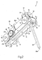
- the leaves 4 are mobile between a closing position ( Figure 1 ) and an opening position ( Figure 4b ) of the opening 2 under the thrust of a conveying device 12 comprising a carriage 13, which is mounted within the guide 8 and comprises, in turn, a supporting frame 14 provided with two mutually parallel axles 15, 16, each of which is coupled in a rotatable way to the frame 14 so as to turn, with respect to the frame 14 itself, about a longitudinal axis 17 thereof parallel to a horizontal direction 18 orthogonal to the directions 5 and 9, and carries fitted to its ends two wheels 19 engaged in the two tracks 11.
- a conveying device 12 comprising a carriage 13, which is mounted within the guide 8 and comprises, in turn, a supporting frame 14 provided with two mutually parallel axles 15, 16, each of which is coupled in a rotatable way to the frame 14 so as to turn, with respect to the frame 14 itself, about a longitudinal axis 17 thereof parallel to a horizontal direction 18 orthogonal to the directions 5 and 9, and carries fitted to its ends two wheels 19 engaged in the
- the axle 15 is set in rotation about it own axis 17 by an actuator device 20 comprising an electric motor 20a, which is mounted on the frame 14 and has an output shaft defined by a screw 21, which extends parallel to the direction 9, and meshes with a helical gear 22, fitted on a supporting shaft 23 parallel to the direction 18.
- the shaft 23 is mounted in a coaxial position facing a transmission shaft 24 coupled, normally, in an angularly fixed way to the shaft 23 itself via the interposition of a clutch 25, in the case in point a clutch of an electrical type.
- the shaft 24 sets in rotation the axle 15 via a chain 26 of gears comprising a first gear 27a fitted on the shaft 24 and a second gear 27b fitted on the axle 15 and coupled to the gear 27a itself.
- the carriage 13 is connected to the leaf 4b via a dragging rod 28, which extends downwards from the carriage 13, has a longitudinal axis 28a parallel to the direction 5, is coupled in a rotatable and axially slidable way, in a position corresponding to a bottom end thereof, to an outer longitudinal edge of the leaf 4b, and is provided with a substantially parallelepipedal top bushing 29, which is fixed to a top end of the rod 28 in a direction transverse to the axis 28a and is slidably coupled to a guide 30 made in the frame 14 parallel to the direction 9.
- the bushing 29 is moreover coupled via a screw/nut screw coupling, to a screw 31 of a corresponding actuation device 32, which defines part of the conveying device 12 and comprises an electric motor 33, which is mounted on the frame 14 and has an output shaft 34 opposite to the screw 21 of the motor 20a.
- the shaft 34 extends parallel to the direction 9 and is connected to the screw 31 via a belt transmission 35 of a known type for setting the screw 31 in rotation and imparting upon the bushing 29, and hence upon the rod 28, rectilinear displacements along the guide 30 in the direction 9.
- Each electric motor 20a, 33 is supplied via a corresponding electrical-sliding-contact supply device 36 comprising a plurality of guides 37 made of conductive material (in the case in point, two guides 37) fixed within the sectional element 10 parallel to the direction 9, and a plurality of electrical contacts 38, which are also made of conductive material, are equal in number to the corresponding guides 37, project upwards from the corresponding motor 20a, 33, and are designed to engage slidably the corresponding guides 37 during advance of the carriage 13 along the guide 8.
- a corresponding electrical-sliding-contact supply device 36 comprising a plurality of guides 37 made of conductive material (in the case in point, two guides 37) fixed within the sectional element 10 parallel to the direction 9, and a plurality of electrical contacts 38, which are also made of conductive material, are equal in number to the corresponding guides 37, project upwards from the corresponding motor 20a, 33, and are designed to engage slidably the corresponding guides 37 during advance of the carriage 13 along the guide 8.
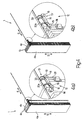
- the carriage 13 is displaced along the guide 8 via the actuation device 20 so that, by combining the displacement of the carriage 13 in the direction 9 with the rotation of the leaves 4a, 4b, and 4c about the corresponding axes 6, 7, and 28a, the leaves 4a, 4b, and 4c will be folded substantially in contact with one another ( Figure 4a ).
- a guide device (of a known type and not illustrated), which comprises a shaped guide projecting laterally from the guide 8 and, for each leaf 4a, 4b, and 4c, a corresponding roller designed to engage the shaped guide itself.
- the carriage 13 is displaced along the guide 8 via the actuation device 20 so that, by combining the displacement of the carriage 13 in the direction 9 with the rotation of the leaves 4a, 4b, and 4c about the corresponding axes 6, 7, and 28a, the leaves 4a, 4b, and 4c set themselves in a position substantially coplanar to one another.
- the door 1 thus presents a number of advantages principally resulting from the fact that:
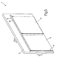
- Figure 5 differs from what is illustrated in the preceding figures only for the fact that, therein, the leaves 4a, 4b, and 4c are eliminated and replaced, in the case in point, with a single slidable leaf 4, which can move in the direction 9 between a closing position (illustrated with a solid line in Figure 5 ) and an opening position (illustrated with a dashed line in Figure 5 ) of the opening 2.
Landscapes
- Engineering & Computer Science (AREA)
- Civil Engineering (AREA)
- Structural Engineering (AREA)
- Power-Operated Mechanisms For Wings (AREA)
- Glass Compositions (AREA)
- Lock And Its Accessories (AREA)
- Transition And Organic Metals Composition Catalysts For Addition Polymerization (AREA)
- Platform Screen Doors And Railroad Systems (AREA)
Claims (9)
- Industrietor, welches zumindest einen Flügel (4) und ein Betätigungsmittel (12) zum Verlagern des Flügels (4) zwischen einer geöffneten und einer geschlossenen Position des Industrietors aufweist, wobei das Betätigungsmittel (12) einen Fahrwagen (13) zum Bewegen des Flügels (4), ein erstes Führungsmittel (8) zum Führen des Fahrwagens (13) und ein erstes Antriebsmittel (20) zum Bewegen des Fahrwagens (13) entlang des ersten Führungsmittels (8) und in einer vorbestimmten Richtung (9) aufweist, wobei das erste Antriebsmittel (20) von dem Fahrwagen (13) getragen ist und einen auf dem Fahrwagen (13) montierten ersten Motor (20a) zum Verlagern des Fahrwagens (13) entlang des ersten Führungsmittels (8) aufweist; dadurch gekennzeichnet, dass der Flügel (4) derart gleitbar mit dem Fahrwagen (13) wirkverbunden ist, dass dieser relativ zu dem Fahrwagen (13) in der Richtung (9) verlagerbar ist; und dass das Betätigungsmittel (12) ein zweites Antriebsmittel (32) zum Verlagern des Flügels (4) entlang des Fahrwagens (13) aufweist.
- Industrietor nach Anspruch 1, wobei der Fahrwagen (13) einen Rahmen (14), zumindest eine Achse (15), welche zum Rotieren um eine vorbestimmte longitudinale Mittelachse (17) der Achse (15) rotierbar mit dem Rahmen (14) wirkverbunden ist, und zumindest ein Rad (19) zum Bewegen des Fahrwagens (13) entlang dem ersten Führungsmittel (8) aufweist; wobei der erste Motor (20a) auf dem Rahmen (14) montiert ist und eine erste Ausgangswelle (21) aufweist, welche zum Aufbringen einer Rotationsbewegung auf die Achse (15) um die Mittelachse (17) ausgebildet ist.
- Industrietor nach Anspruch 2, wobei das erste Antriebsmittel (20) ein erstes Kupplungsmittel (25) zum Verbinden der Achse (15) mit der ersten Ausgangswelle (21) aufweist; wobei das erste Kupplungsmittel (25) beweglich ist zwischen einer Kupplungsposition, in welcher die Achse (15) unter der Wirkung der ersten Ausgangswelle (21) um die Mittelachse (17) rotiert, und einer Abkupplungsposition, in welcher die ersten Ausgangswelle (21) von der Achse (15) abgekuppelt ist.
- Industrietor nach Anspruch 3, wobei das erste Kupplungsmittel (25) eine Kupplung (25) aufweist, welche zwischen der ersten Ausgangswelle (21) und der Achse (15) angeordnet ist.
- Industrietor nach einem der vorhergehenden Ansprüche, wobei der erste Motor (20) ein Elektromotor ist; und wobei ein erstes Versorgungsmittel (36) zum elektrischen Versorgen des ersten Motors (20) entlang des ersten Führungsmittels (8) angeordnet ist.
- Industrietor nach einem der vorhergehenden Ansprüche, wobei das zweite Antriebsmittel (32) von dem Fahrwagen (13) getragen ist, ein Mittel (28) zum Mitschleppen des Flügels (4), ein zweites Führungsmittel (30) des Fahrwagens (13), welches gleitend mit dem Schleppmittel (28) in Wirkverbindung ist, und ein en zweiten Motor (33) aufweist, welcher zum Verlagern des Schleppmittels (28) entlang des zweiten Führungsmittels (30) auf dem Fahrwagen (13) montiert ist.
- Industrietor nach Anspruch 6, wobei der zweite Motor (33) eine zweite Ausgangswelle (34) aufweist; und wobei zweite Kupplungsmittel (31, 35) zum Verbinden der zweiten Ausgangswelle (34) und des Schleppmittels (28) vorgesehen sind.
- Industrietor nach Anspruch 7, wobei die zweiten Kupplungsmittel (31, 35) eine Spindel/Mutter-Einrichtung aufweisen, welche zwischen der zweiten Ausgangswelle (34) und dem Schleppmittel (28) angeordnet ist.
- Industrietor nach Anspruch 7 oder 8, wobei der zweite Motor (33) ein Elektromotor ist; und wobei ein zweites Versorgungsmittel (36) zum elektrischen Versorgen des ersten Motors (20) entlang des ersten Führungsmittels (8) angeordnet ist.
Applications Claiming Priority (2)
| Application Number | Priority Date | Filing Date | Title |
|---|---|---|---|
| IT000170A ITBO20060170A1 (it) | 2006-03-10 | 2006-03-10 | Portone industriale |
| PCT/IB2007/000559 WO2007105057A2 (en) | 2006-03-10 | 2007-03-09 | Industrial door |
Publications (2)
| Publication Number | Publication Date |
|---|---|
| EP2004941A2 EP2004941A2 (de) | 2008-12-24 |
| EP2004941B1 true EP2004941B1 (de) | 2010-05-19 |
Family
ID=38373862
Family Applications (1)
| Application Number | Title | Priority Date | Filing Date |
|---|---|---|---|
| EP07713109A Not-in-force EP2004941B1 (de) | 2006-03-10 | 2007-03-09 | Industrietor |
Country Status (5)
| Country | Link |
|---|---|
| EP (1) | EP2004941B1 (de) |
| AT (1) | ATE468463T1 (de) |
| DE (1) | DE602007006651D1 (de) |
| IT (1) | ITBO20060170A1 (de) |
| WO (1) | WO2007105057A2 (de) |
Cited By (1)
| Publication number | Priority date | Publication date | Assignee | Title |
|---|---|---|---|---|
| CN102330529A (zh) * | 2011-07-05 | 2012-01-25 | 浙江大学 | 电动轨道折叠门 |
Families Citing this family (6)
| Publication number | Priority date | Publication date | Assignee | Title |
|---|---|---|---|---|
| DE102009011947A1 (de) * | 2009-03-10 | 2010-09-16 | Dorma Gmbh + Co. Kg | Antriebssystem zum Antrieb und zur Führung eines Wandelelementes für ein Raumtrennwandsystem |
| EP2248980B1 (de) * | 2009-05-07 | 2013-07-03 | Griesser Holding AG | Schiebe-Falt-Laden |
| US9353568B2 (en) | 2009-08-17 | 2016-05-31 | Won-Door Corporation | Methods, apparatuses, and systems for driving a movable partition |
| US8365796B2 (en) | 2010-04-12 | 2013-02-05 | Won-Door Corporation | Methods, apparatuses, and systems for movable partitions |
| EP2653642B1 (de) * | 2012-04-20 | 2019-03-13 | Hawa Sliding Solutions AG | Verfahren für den betrieb eines faltsystems und faltsystem |
| FR3003888A1 (fr) * | 2013-03-29 | 2014-10-03 | Henri Jaffrain | Motorisation de multi portes |
Family Cites Families (6)
| Publication number | Priority date | Publication date | Assignee | Title |
|---|---|---|---|---|
| US3289741A (en) * | 1966-12-06 | Self-propelled partition assembly | ||
| GB532347A (en) * | 1939-08-16 | 1941-01-22 | King Ltd Geo W | Improvements in or relating to folding doors, partitions or the like |
| DE9214915U1 (de) * | 1992-11-03 | 1993-02-25 | abopart Viol und Partner GmbH & Co KG, 2903 Bad Zwischenahn | Versetzbare Trennwand mit mehreren plattenförmigen Wandelementen |
| ES2148989T3 (es) * | 1996-07-25 | 2000-10-16 | Inventio Ag | Accionamiento de puerta. |
| DE29808916U1 (de) * | 1998-05-16 | 1999-11-25 | Hüppe Form Raumtrennsysteme GmbH, 26133 Oldenburg | Trennwandelement mit eigener Antriebseinrichtung |
| DE19932891B4 (de) * | 1999-07-19 | 2004-01-08 | Dorma Gmbh + Co. Kg | Antrieb für eine mehrere Wandelemente umfassende Schiebewand |
-
2006
- 2006-03-10 IT IT000170A patent/ITBO20060170A1/it unknown
-
2007
- 2007-03-09 WO PCT/IB2007/000559 patent/WO2007105057A2/en not_active Ceased
- 2007-03-09 AT AT07713109T patent/ATE468463T1/de not_active IP Right Cessation
- 2007-03-09 DE DE602007006651T patent/DE602007006651D1/de active Active
- 2007-03-09 EP EP07713109A patent/EP2004941B1/de not_active Not-in-force
Cited By (2)
| Publication number | Priority date | Publication date | Assignee | Title |
|---|---|---|---|---|
| CN102330529A (zh) * | 2011-07-05 | 2012-01-25 | 浙江大学 | 电动轨道折叠门 |
| CN102330529B (zh) * | 2011-07-05 | 2013-03-27 | 浙江大学 | 电动轨道折叠门 |
Also Published As
| Publication number | Publication date |
|---|---|
| WO2007105057A3 (en) | 2007-11-15 |
| WO2007105057A2 (en) | 2007-09-20 |
| ITBO20060170A1 (it) | 2007-09-11 |
| EP2004941A2 (de) | 2008-12-24 |
| ATE468463T1 (de) | 2010-06-15 |
| DE602007006651D1 (de) | 2010-07-01 |
Similar Documents
| Publication | Publication Date | Title |
|---|---|---|
| EP2004941B1 (de) | Industrietor | |
| CN204497071U (zh) | 电容器素子卷绕装置 | |
| CN211003169U (zh) | 伸缩输送装置 | |
| CN107208447B (zh) | 链式推移致动器 | |
| US20100229469A1 (en) | Opening/closing unit and opening/closing unit for vehicle windows | |
| JP6278877B2 (ja) | 可動扉装置 | |
| CN114570802A (zh) | 双向弯圆机 | |
| ITTO970204A1 (it) | Dispositivo per l'alimentazione di fogli ad una macchina piegatrice. | |
| EP1964998A2 (de) | Einziehbare Markise | |
| KR100985506B1 (ko) | 경편기의 가이드바 구동장치 | |
| EP2034581A1 (de) | Elektrische Stromzuführstruktur | |
| CN104963076B (zh) | 一种电脑横机的罗拉装置 | |
| CN208828175U (zh) | 一种装盒机推杆装置 | |
| KR101059073B1 (ko) | 가변형 롤포밍장치 | |
| CN110250877B (zh) | 双开式伸缩电动窗帘轨道 | |
| CN107072403B (zh) | 线性双致动器 | |
| ITTO960142A1 (it) | Testa traspositrice per la formazione di conduttori ctc. | |
| CN101428312A (zh) | 单轴变截面辊弯成型机 | |
| CN101687687B (zh) | 使用于弯曲玻璃板的输送辊偏转的方法和使用该方法的组件 | |
| GB2086982A (en) | Supporting lengths of chain in draw chain drives | |
| CN116493450A (zh) | 一种钣金的折弯装置 | |
| CN210365780U (zh) | 一种翻转机构 | |
| CN210643637U (zh) | 一种心连心换挡的双导轨电动窗帘系统 | |
| CN209973481U (zh) | 一种防火保温一体化复合板生产设备 | |
| CN210611821U (zh) | 双开式伸缩电动窗帘轨道 |
Legal Events
| Date | Code | Title | Description |
|---|---|---|---|
| PUAI | Public reference made under article 153(3) epc to a published international application that has entered the european phase |
Free format text: ORIGINAL CODE: 0009012 |
|
| 17P | Request for examination filed |
Effective date: 20081010 |
|
| AK | Designated contracting states |
Kind code of ref document: A2 Designated state(s): AT BE BG CH CY CZ DE DK EE ES FI FR GB GR HU IE IS IT LI LT LU LV MC MT NL PL PT RO SE SI SK TR |
|
| RAP1 | Party data changed (applicant data changed or rights of an application transferred) |
Owner name: MITEC S.R.L. CON UNICO SOCIO Owner name: BENEDETTI PINO DITTA INDIVIDUALE |
|
| 17Q | First examination report despatched |
Effective date: 20090331 |
|
| GRAP | Despatch of communication of intention to grant a patent |
Free format text: ORIGINAL CODE: EPIDOSNIGR1 |
|
| DAX | Request for extension of the european patent (deleted) | ||
| GRAS | Grant fee paid |
Free format text: ORIGINAL CODE: EPIDOSNIGR3 |
|
| GRAA | (expected) grant |
Free format text: ORIGINAL CODE: 0009210 |
|
| AK | Designated contracting states |
Kind code of ref document: B1 Designated state(s): AT BE BG CH CY CZ DE DK EE ES FI FR GB GR HU IE IS IT LI LT LU LV MC MT NL PL PT RO SE SI SK TR |
|
| REG | Reference to a national code |
Ref country code: GB Ref legal event code: FG4D |
|
| REG | Reference to a national code |
Ref country code: CH Ref legal event code: EP |
|
| REG | Reference to a national code |
Ref country code: IE Ref legal event code: FG4D |
|
| REF | Corresponds to: |
Ref document number: 602007006651 Country of ref document: DE Date of ref document: 20100701 Kind code of ref document: P |
|
| REG | Reference to a national code |
Ref country code: NL Ref legal event code: VDEP Effective date: 20100519 |
|
| LTIE | Lt: invalidation of european patent or patent extension |
Effective date: 20100519 |
|
| PG25 | Lapsed in a contracting state [announced via postgrant information from national office to epo] |
Ref country code: ES Free format text: LAPSE BECAUSE OF FAILURE TO SUBMIT A TRANSLATION OF THE DESCRIPTION OR TO PAY THE FEE WITHIN THE PRESCRIBED TIME-LIMIT Effective date: 20100830 Ref country code: SE Free format text: LAPSE BECAUSE OF FAILURE TO SUBMIT A TRANSLATION OF THE DESCRIPTION OR TO PAY THE FEE WITHIN THE PRESCRIBED TIME-LIMIT Effective date: 20100519 Ref country code: LT Free format text: LAPSE BECAUSE OF FAILURE TO SUBMIT A TRANSLATION OF THE DESCRIPTION OR TO PAY THE FEE WITHIN THE PRESCRIBED TIME-LIMIT Effective date: 20100519 |
|
| PG25 | Lapsed in a contracting state [announced via postgrant information from national office to epo] |
Ref country code: LV Free format text: LAPSE BECAUSE OF FAILURE TO SUBMIT A TRANSLATION OF THE DESCRIPTION OR TO PAY THE FEE WITHIN THE PRESCRIBED TIME-LIMIT Effective date: 20100519 Ref country code: SI Free format text: LAPSE BECAUSE OF FAILURE TO SUBMIT A TRANSLATION OF THE DESCRIPTION OR TO PAY THE FEE WITHIN THE PRESCRIBED TIME-LIMIT Effective date: 20100519 Ref country code: IS Free format text: LAPSE BECAUSE OF FAILURE TO SUBMIT A TRANSLATION OF THE DESCRIPTION OR TO PAY THE FEE WITHIN THE PRESCRIBED TIME-LIMIT Effective date: 20100919 Ref country code: FI Free format text: LAPSE BECAUSE OF FAILURE TO SUBMIT A TRANSLATION OF THE DESCRIPTION OR TO PAY THE FEE WITHIN THE PRESCRIBED TIME-LIMIT Effective date: 20100519 Ref country code: AT Free format text: LAPSE BECAUSE OF FAILURE TO SUBMIT A TRANSLATION OF THE DESCRIPTION OR TO PAY THE FEE WITHIN THE PRESCRIBED TIME-LIMIT Effective date: 20100519 |
|
| PG25 | Lapsed in a contracting state [announced via postgrant information from national office to epo] |
Ref country code: CY Free format text: LAPSE BECAUSE OF FAILURE TO SUBMIT A TRANSLATION OF THE DESCRIPTION OR TO PAY THE FEE WITHIN THE PRESCRIBED TIME-LIMIT Effective date: 20100602 Ref country code: PL Free format text: LAPSE BECAUSE OF FAILURE TO SUBMIT A TRANSLATION OF THE DESCRIPTION OR TO PAY THE FEE WITHIN THE PRESCRIBED TIME-LIMIT Effective date: 20100519 |
|
| PG25 | Lapsed in a contracting state [announced via postgrant information from national office to epo] |
Ref country code: PT Free format text: LAPSE BECAUSE OF FAILURE TO SUBMIT A TRANSLATION OF THE DESCRIPTION OR TO PAY THE FEE WITHIN THE PRESCRIBED TIME-LIMIT Effective date: 20100920 Ref country code: EE Free format text: LAPSE BECAUSE OF FAILURE TO SUBMIT A TRANSLATION OF THE DESCRIPTION OR TO PAY THE FEE WITHIN THE PRESCRIBED TIME-LIMIT Effective date: 20100519 Ref country code: DK Free format text: LAPSE BECAUSE OF FAILURE TO SUBMIT A TRANSLATION OF THE DESCRIPTION OR TO PAY THE FEE WITHIN THE PRESCRIBED TIME-LIMIT Effective date: 20100519 Ref country code: NL Free format text: LAPSE BECAUSE OF FAILURE TO SUBMIT A TRANSLATION OF THE DESCRIPTION OR TO PAY THE FEE WITHIN THE PRESCRIBED TIME-LIMIT Effective date: 20100519 |
|
| PG25 | Lapsed in a contracting state [announced via postgrant information from national office to epo] |
Ref country code: RO Free format text: LAPSE BECAUSE OF FAILURE TO SUBMIT A TRANSLATION OF THE DESCRIPTION OR TO PAY THE FEE WITHIN THE PRESCRIBED TIME-LIMIT Effective date: 20100519 Ref country code: SK Free format text: LAPSE BECAUSE OF FAILURE TO SUBMIT A TRANSLATION OF THE DESCRIPTION OR TO PAY THE FEE WITHIN THE PRESCRIBED TIME-LIMIT Effective date: 20100519 Ref country code: CZ Free format text: LAPSE BECAUSE OF FAILURE TO SUBMIT A TRANSLATION OF THE DESCRIPTION OR TO PAY THE FEE WITHIN THE PRESCRIBED TIME-LIMIT Effective date: 20100519 Ref country code: BE Free format text: LAPSE BECAUSE OF FAILURE TO SUBMIT A TRANSLATION OF THE DESCRIPTION OR TO PAY THE FEE WITHIN THE PRESCRIBED TIME-LIMIT Effective date: 20100519 |
|
| PLBE | No opposition filed within time limit |
Free format text: ORIGINAL CODE: 0009261 |
|
| STAA | Information on the status of an ep patent application or granted ep patent |
Free format text: STATUS: NO OPPOSITION FILED WITHIN TIME LIMIT |
|
| 26N | No opposition filed |
Effective date: 20110222 |
|
| PG25 | Lapsed in a contracting state [announced via postgrant information from national office to epo] |
Ref country code: GR Free format text: LAPSE BECAUSE OF FAILURE TO SUBMIT A TRANSLATION OF THE DESCRIPTION OR TO PAY THE FEE WITHIN THE PRESCRIBED TIME-LIMIT Effective date: 20100820 |
|
| REG | Reference to a national code |
Ref country code: DE Ref legal event code: R097 Ref document number: 602007006651 Country of ref document: DE Effective date: 20110221 |
|
| PG25 | Lapsed in a contracting state [announced via postgrant information from national office to epo] |
Ref country code: MC Free format text: LAPSE BECAUSE OF NON-PAYMENT OF DUE FEES Effective date: 20110331 |
|
| REG | Reference to a national code |
Ref country code: CH Ref legal event code: PL |
|
| GBPC | Gb: european patent ceased through non-payment of renewal fee |
Effective date: 20110309 |
|
| REG | Reference to a national code |
Ref country code: FR Ref legal event code: ST Effective date: 20111130 |
|
| PG25 | Lapsed in a contracting state [announced via postgrant information from national office to epo] |
Ref country code: MT Free format text: LAPSE BECAUSE OF FAILURE TO SUBMIT A TRANSLATION OF THE DESCRIPTION OR TO PAY THE FEE WITHIN THE PRESCRIBED TIME-LIMIT Effective date: 20100519 |
|
| REG | Reference to a national code |
Ref country code: IE Ref legal event code: MM4A |
|
| PG25 | Lapsed in a contracting state [announced via postgrant information from national office to epo] |
Ref country code: LI Free format text: LAPSE BECAUSE OF NON-PAYMENT OF DUE FEES Effective date: 20110331 Ref country code: CH Free format text: LAPSE BECAUSE OF NON-PAYMENT OF DUE FEES Effective date: 20110331 Ref country code: FR Free format text: LAPSE BECAUSE OF NON-PAYMENT OF DUE FEES Effective date: 20110331 Ref country code: IE Free format text: LAPSE BECAUSE OF NON-PAYMENT OF DUE FEES Effective date: 20110309 Ref country code: DE Free format text: LAPSE BECAUSE OF NON-PAYMENT OF DUE FEES Effective date: 20111001 |
|
| REG | Reference to a national code |
Ref country code: DE Ref legal event code: R119 Ref document number: 602007006651 Country of ref document: DE Effective date: 20111001 |
|
| PG25 | Lapsed in a contracting state [announced via postgrant information from national office to epo] |
Ref country code: IT Free format text: LAPSE BECAUSE OF NON-PAYMENT OF DUE FEES Effective date: 20110309 Ref country code: GB Free format text: LAPSE BECAUSE OF NON-PAYMENT OF DUE FEES Effective date: 20110309 |
|
| PG25 | Lapsed in a contracting state [announced via postgrant information from national office to epo] |
Ref country code: LU Free format text: LAPSE BECAUSE OF NON-PAYMENT OF DUE FEES Effective date: 20110309 |
|
| PG25 | Lapsed in a contracting state [announced via postgrant information from national office to epo] |
Ref country code: TR Free format text: LAPSE BECAUSE OF FAILURE TO SUBMIT A TRANSLATION OF THE DESCRIPTION OR TO PAY THE FEE WITHIN THE PRESCRIBED TIME-LIMIT Effective date: 20100519 Ref country code: BG Free format text: LAPSE BECAUSE OF FAILURE TO SUBMIT A TRANSLATION OF THE DESCRIPTION OR TO PAY THE FEE WITHIN THE PRESCRIBED TIME-LIMIT Effective date: 20100819 |
|
| PG25 | Lapsed in a contracting state [announced via postgrant information from national office to epo] |
Ref country code: HU Free format text: LAPSE BECAUSE OF FAILURE TO SUBMIT A TRANSLATION OF THE DESCRIPTION OR TO PAY THE FEE WITHIN THE PRESCRIBED TIME-LIMIT Effective date: 20100519 |