EP2005207B1 - Procédé et système permettant d'estimer des directions d'arrivée dans des scénarios à taille d'échantillon réduite ou faible puissance - Google Patents
Procédé et système permettant d'estimer des directions d'arrivée dans des scénarios à taille d'échantillon réduite ou faible puissance Download PDFInfo
- Publication number
- EP2005207B1 EP2005207B1 EP06707487A EP06707487A EP2005207B1 EP 2005207 B1 EP2005207 B1 EP 2005207B1 EP 06707487 A EP06707487 A EP 06707487A EP 06707487 A EP06707487 A EP 06707487A EP 2005207 B1 EP2005207 B1 EP 2005207B1
- Authority
- EP
- European Patent Office
- Prior art keywords
- array
- cost function
- receiving elements
- arrival
- function
- Prior art date
- Legal status (The legal status is an assumption and is not a legal conclusion. Google has not performed a legal analysis and makes no representation as to the accuracy of the status listed.)
- Expired - Lifetime
Links
Images


Classifications
-
- G—PHYSICS
- G01—MEASURING; TESTING
- G01S—RADIO DIRECTION-FINDING; RADIO NAVIGATION; DETERMINING DISTANCE OR VELOCITY BY USE OF RADIO WAVES; LOCATING OR PRESENCE-DETECTING BY USE OF THE REFLECTION OR RERADIATION OF RADIO WAVES; ANALOGOUS ARRANGEMENTS USING OTHER WAVES
- G01S3/00—Direction-finders for determining the direction from which infrasonic, sonic, ultrasonic or electromagnetic waves, or particle emission, not having a directional significance, are being received
- G01S3/02—Direction-finders for determining the direction from which infrasonic, sonic, ultrasonic or electromagnetic waves, or particle emission, not having a directional significance, are being received using radio waves
- G01S3/74—Multi-channel systems specially adapted for direction-finding, i.e. having a single antenna system capable of giving simultaneous indications of the directions of different signals
Definitions
- the present invention relates to a method and a system for determining the direction of arrival of one or multiple radio or acoustic waveforms and, more particularly, to such a method and system especially advantageous in situations where the number of available observations is small, or the available observations are received with low power.
- DoA direction of arrival
- angle of arrival angle of arrival
- the estimation of the impinging angles becomes feasible when an array of multiple sensor or antenna elements spatially distributed in a particular region is employed.
- Each of the sensors is equipped with a radio-frequency/acoustic front-end and its corresponding signal processing technology.
- the waveforms or signals received by each of the array elements are processed together by a central processing unit that determines the direction of arrival of the different sources in the scenario.
- the sources might be transmitters themselves, or they might be reflectors of the acoustic or radio waveforms generated by other sources.
- the ML method gives the best performance, although this is at the expense of a much higher computational complexity (the ML solution is computed by optimizing a cost function in multiple variables and the solution is obtained from a multidimensional search).
- Both the Capon and the MUSIC spectral estimators are much more efficient in terms of computational burden, because the solution is obtained from a one-dimensional search.
- the difference between these two methods is the fact that the MUSIC method, contrary to the Capon solution, exploits the eigenstructure of the spatial correlation matrix of the observations. In practice, it has been shown both theoretically and experimentally, that DoA estimation techniques based on the eigenstructure methods are superior to other traditional one-dimensional search based methods such as the Capon estimator.
- V. Girko introduced the theory of G-estimation [ V. Girko, "An Introduction to Statistical Analysis of Random Arrays", The Netherlands: VSP, 1998 ]. This theory provides a systematic approach for deriving estimators with excellent properties in the small sample size regime.
- subspace-based methods such as MUSIC
- MUSIC subspace-based methods
- Several methods have been proposed to alleviate the bad performance of the MUSIC method in the low power and/or sample size region, although most of these methods can only be applied to some particular array geometries.
- the polynomial-root MUSIC method or the state-space approach can only operate on uniform linear array architectures (that is to say, on arrays where all the sensors/antennas are equispaced and located along a straight line).
- DoAs directions-of-arrival
- our method will hereinafter be referred to as the GMUSIC method.
- Our method can be further complemented with some enhancements of the traditional MUSIC technique, such as polynomial rooting, beamspace projection, sequential estimation or spatial smoothing.
- the object of the present invention is a new method and system for DoA estimation for multi-sensor or multi-antenna array receivers.
- the main particularity of the proposed invention is the fact that it overcomes the threshold effect of traditional eigenstructure methods, allowing for correct multiple DoA detection in situations where either the number of available samples or the power of the received waveforms are not suffiently high to guarantee DoA detection by conventional means based on one-dimensional exploration of the angle of arrival.
- the proposed method of DoA identification comprises the selection of the lowest or highest peaks of a cost function that depends on the angle of exploration. This function is constructed from the eigenvalues and eigenvectors of the estimated covariance matrix of the observation.
- Another advantage of our method when compared with the well-known improvements of the MUSIC algorithm, is that it is valid for any type of array of receiving elements, such as linear array, non-linear array, uniform array, circular array, triangular array, and so on.
- the proposed method for determining the direction of arrival of at least one radio waveform comprises the steps of: receiving at least one waveform at M receiving elements; obtaining one detected signal at the output of each of the M receiving elements; processing said M detected signals for obtaining M processed signals; sampling at N time instants said M processed signals; from the samples obtained in the previous step, creating N column vectors y(1), ..., y(N), wherein y(n) represents, for a sampling instant n, a column vector with M rows, each of the M rows containing the sample value associated to the corresponding receiving element at that sampling instant n; from the collection of N column vectors, calculating a sample spatial correlation matrix R ⁇ , obtaining all the eigenvectors ê i and all the eigenvalues ⁇ i from the sample spatial correlation matrix R ⁇ ; from all the eigenvectors ê i and all the eigenvalues ⁇ i , obtaining a set of signal dependent parameters ⁇ k ; from the eigenvalues
- Finding the K solutions from said certain cost function is done either by selecting K deepest local minima of a certain cost function, or by selecting K highest local maxima of said cost function.
- the present invention also provides a system which comprises means adapted for carrying out the steps of the method, as well as a computer program comprising computer program code means adapted to perform the steps of the method when said program is run on a computer, a digital signal processor, a field-programmable gate array, an application-specific integrated circuit, a microprocessor, a micro-controller, or any other form of programmable hardware.
- One or several waveforms (w a , w b , w c ...) are received by at least one receiving element (1, 2, 3, 4). These waveforms are preferably radio-frequency or microwave signals.
- the receiving elements are preferably a sensor array composed of multiple sensors or antennae.
- the one or several waveforms (w a , w b , w c ...) come from respective one or several sources, which might be transmitters themselves, or they might be reflectors of the acoustic or radio waveforms generated by other sources.
- the waveform or signal (d 1 , d 2 , d 3 , d 4 ...) captured or detected by each one of these receiving elements (1, 2, 3, 4...) is received by a pre-processing unit or front-end (30, 31, 32, 33%) that pre-processes the signal (f 1 , f 2 , f 3 , f 4 %) so that it can be further processed by the signal processing unit (40).
- the signal processing unit (40) takes samples of the signals (f 1 , f 2 , f 3 , f 4 %) coming from the front-ends (30, 31, 32, 33%) at certain synchronized time instants, and generates a collection of discrete time multidimensional observations or snapshots [(f 1 1, f 1 2 , f 1 3 , f 1 4 ...), (f 2 1 , f 2 2 , f 2 3 , f 2 4 ...), ..., (f N 1 , f N 2 , f N 3 , f N 4 ...)], wherein N is a natural number which represents the number of time instants at which samples of (f 1 , f 2 , f 3 , f 4 ...) are taken.
- the signal processing unit (40) acquires a collection of M values (f n 1 , f n 2 , ..., f n M ) coming from the M different front-ends (30, 31, 32, 33). These values (f n 1 , f n 2 , ..., f n M ) may be real-valued or complex-valued depending on the characteristics of the receiver.
- the M values are stacked into an M x 1 column vector y(n), where n is a natural number that indexes the sampling instant associated with the observation.
- the signal processing unit (40) works with a collection of N column vectors or snapshots, ⁇ y(1), ..., y( N ) ⁇ .
- the number N of available snapshots can be lower than, equal to or higher than the number of sensors M .
- the signal received in the mth antenna will be s( n )exp(j2 ⁇ ( m- 1)d/ ⁇ sin( ⁇ )).
- this column vector s( n ) ⁇ a( ⁇ )
- s( n ) is the transmitted signal
- a ( ⁇ ) is an M x1 with the mth entry equal to exp(j2 ⁇ ( m -1)d/ ⁇ sin( ⁇ )).
- the column vector a( ⁇ ) can be constructed for any array geometry, and it gives the array response as a complex function of the direction of arrival ⁇ .
- the response of the receiving chains is measured at the signal processing unit (40), and the result of this measures is called a( ⁇ ).
- this process of calibration must be done for any value of ⁇ within the exploration margin, such that the collection of all the possible functions a( ⁇ ) is obtained for every value of ⁇ .
- the process of calibration is done prior to the exploration itself, in practice it is impossible to know a( ⁇ ) for any value of ⁇ (the experiment would have to be repeated for infinite values of ⁇ ). That is why, in practice, a collection of as many discrete values of ⁇ as possible and as close to each other as possible, is selected, in order to evaluate and know the function a( ⁇ ) during the process of calibration.
- the cost function ⁇ ( ⁇ ) is normally evaluated for the values of ⁇ for which the function a( ⁇ ) is known, by interpolating the rest of the values of ⁇ .
- planar arrays that is to say, arrays in which the receiving elements are distributed on a plane
- the function a( ⁇ ) depends on two angles (elevation and azimuth) instead of on one angle (this being the case for linear arrays, that is to say, arrays in which the receiving elements are distributed on a straight line).
- ⁇ can be either a parameter or a vector or parameters, whose values are angles that define the direction of arrival.
- the array of M receiving elements (1, 2, 3, 4...) can also be calibrated as follows: exposing a collection of reference signals to the array of M receiving elements (1, 2, 3, 4...) ; measuring, at the signal processing unit (40), the response of the received reference signals obtained at the output of the M pre-processing units (30,31,32,33,%), and modifying the response of the M pre-processing units (30,31,32,33,%) in such a way that the signals measured at the output of the M pre-processing units (30,31,32,33,...) are as close as possible to the reference signals inserted in the first step.
- Fig. 2 illustrates a preferred method for obtaining the directions of arrival ⁇ 1 ,..., ⁇ k from the observations ⁇ y(1), ..., y(N) ⁇ .
- the proposed method uses the teachings of the theory of G-estimators introduced in the "State of the Art", and is referred to as MUSIC.
- MUSIC G-estimators
- GMUSIC is designed to provide consistent estimates of the DoAs when both the sample size and the number of sensors or antennas have the same order of magnitude. This ensures a significant improvement of the performance in the low power and/or low sample size regime.
- the MUSIC algorithm provides consistent results of the estimated directions-of-arrival or angles-of-arrival when N is high but M remains fixed, that is to say, when N is high relative to M.
- our algorithm provides consistent and reliable results when both N and M are high, that is to say, when M and N are comparable to each other in terms of order of magnitude. In practice, this means that our algorithm behaves in a very reliable way even if the number of samples N is not much higher than the number of sensors or antennae M. This does not happen in the original MUSIC algorithm. Therefore, our algorithm behaves much better than the MUSIC algorithm in the "low-sample size regime".
- the method comprises the following steps:
- the present invention exploits the information from all the eigenvectors, not only of those associated with the lowest eigenvalues (as it is the case in the traditional MUSIC method). Next, it will be shown that the present invention overcomes the performance breakdown of the MUSIC method in low power or low sample size scenarios.
- Fig. 3 is a graph showing a particular instance of the functions in (7) and (8) above as a function of the angle of arrival, in a situation where two point sources were located at an azimuth of 35° and 40° and their signals were received in Gaussian white noise.
- the traditional MUSIC method is unable to distinguish the two directional sources, and the deepest local minima were located at 39.51° and -32.82°.
- the system is able to recognize two angular sources at 34.92° and 39.58°, very close to the actual values of the source locations.
- the scenario was the same as in Fig. 3 .
- Results are shown for different value of the signal-to-noise ratio (SNR), which is the quotient between the power of the received signals (assumed equal for the two sources) and the power of the background omni directional noise.
- SNR signal-to-noise ratio
- CB Cramér-Rao Bound
- GMUSIC method presents an SNR threshold much lower than the traditional MUSIC.
- the proposed approach shows also a better performance in the high SNR region.
- Fig. 5 represents the probability of detection of the traditional MUSIC and the GMUSIC systems, taken from an average of 10 4 realisations.
- the probability of detection defined as Prob ⁇ ⁇ ⁇ 1 + ⁇ 2 2 > ⁇ ⁇ 1 + ⁇ ⁇ 2 2 , where ⁇ 1 and ⁇ 2 are the DoAs of two point sources in the simulated scenario.
- ⁇ 1 0°
- ⁇ 2 varied from 0° to 10°.
- our method can be further complemented with some enhancements of the traditional MUSIC technique, such as polynomial rooting, beamspace projection, sequential estimation or spatial smoothing, which are shown in the following preferred embodiments.
- the DoAs can also be estimated using a trivial modification of our method as previously defined, as follows. This procedure is usually referred to as polynomial rooting.
- This method consists in devoting spatial degrees of freedom to improving the estimation of the spatial covariance matrix.
- Each of the N column vectors y(1), ..., y(N) is divided into M ss smaller column vectors y Mss (1), ..., y Mss (N), each of said smaller column vectors having L rows;
- the covariance matrix is estimated as follows. First, the covariance or sample spatial correlation matrix at each of the M ss subarrays is estimated as the corresponding sample correlation matrix in (2) or using any other estimation of the spatial correlation matrix as known in the art. That is to say, M ss sample spatial correlation matrices at each of the M ss smaller subarrays are calculated. Second, an LxL covariance matrix estimate R ⁇ is constructed by averaging the M ss covariance matrices obtained in the previous,step. Let a ss ( ⁇ ) denote a column vector formed by selecting the first L rows of a ( ⁇ ).
- the method proposed herein is also applicable to the case where a linear transformation is applied to the observations or the sample covariance matrix in order to improve the properties of the DoA estimation procedure.
Landscapes
- Physics & Mathematics (AREA)
- Engineering & Computer Science (AREA)
- General Physics & Mathematics (AREA)
- Radar, Positioning & Navigation (AREA)
- Remote Sensing (AREA)
- Radar Systems Or Details Thereof (AREA)
- Measurement Of Velocity Or Position Using Acoustic Or Ultrasonic Waves (AREA)
- Mobile Radio Communication Systems (AREA)
Claims (17)
- Procédé pour déterminer la direction d'arrivée d'au moins une forme d'onde radio (wa), comprenant les étapes de:- réception d'au moins une forme d'onde (wa) par M éléments de réception (1, 2, 3, 4...), M étant un nombre entier naturel et M > 1, et obtention d'un signal détecté (d1, d2, d3, d4...) à la sortie de chacun des M éléments de réception (1, 2, 3, 4...);- traitement desdits M signaux détectés (d1, d2, d3, d4...) au niveau de M frontaux (30, 31, 32, 33...) pour obtenir M signaux traités (f1, f2, f3, f4...);- échantillonnage à N temps desdits M signaux traités (f1, f2, f3, f4...) au niveau d'une unité de traitement de signal (40), N étant un nombre entier naturel, pour obtenir des valeurs d'échantillon correspondantes;- à partir des valeurs d'échantillon obtenues dans l'étape précédente, création de N vecteurs de colonne y(1), ..., y(N), où y(n) représente, pour un temps d'échantillonnage n, un vecteur de colonne avec M lignes, chacune des M lignes contenant la valeur d'échantillon associée à l'élément de réception correspondant (1, 2, 3, 4...) à ce temps d'échantillonnage n;- à partir de la collection de N vecteurs de colonne y(1),..., y(N), calcul d'une matrice de corrélation spatiale d'échantillon R̂ ;- obtention de tous les vecteurs propres êk, où k=1...M, et toutes les valeurs propres λ̂1≤λ̂2≤...≤λ̂ M à partir de ladite matrice de corrélation spatiale d'échantillon R̂ ;
le procédé étant caractérisé en ce qu'il comprend les étapes de:- à partir de tous les vecteurs propres êk et toutes les valeurs propres λ̂1≤λ̂2≤...≤λ̂ M obtenues dans l'étape précédente, obtention d'un ensemble de paramètres dépendants du signal µ k , où k=1..M ;- à partir des valeurs propres λ̂1≤λ̂2≤...≤λ̂ M et des paramètres dépendants du signal µ k , précédemment obtenus, construction d'un ensemble de pondérations;- identification de K solutions à partir d'une fonction de coût comprenant ledit ensemble de pondérations, où lesdites solutions sont des minima locaux ou des maxima locaux de ladite fonction de coût, lesdits K minima locaux ou maxima locaux survenant à des directions d'arrivée respectives θ de ladite au moins une forme d'onde radio (Wa), qui sont ainsi déterminées. - Procédé selon la revendication 1, dans lequel l'étape de réception d'au moins une forme d'onde (wa) est effectuée par un réseau de M éléments de capteur ou d'antenne (1, 2, 3, 4...) et où il y a K sources, chacune d'entre elles émettant une forme d'onde.
- Procédé selon la revendication 1, comprenant en outre les étapes de :- acquisition et stockage, au niveau de l'unité de traitement de signal (40), des valeurs d'un vecteur de colonne a(θ), ledit vecteur de colonne a(θ) ayant M lignes correspondant à M éléments de réception respectifs, chacune des M lignes comprenant une fonction qui dépend de la direction d'arrivée θ qui doit être explorée ; et- étalonnage du réseau de M éléments de réception comme suit :- exposition d'une collection de signaux de référence au réseau de M éléments de réception, lesdits signaux de référence simulant des formes d'onde provenant de la direction θ ;- mesure, au niveau de l'unité de traitement de signal (40), de la réponse des signaux de référence reçus obtenu au niveau de chacun des M éléments de réception, de manière à obtenir a(θ).
- Procédé selon la revendication 1, comprenant en outre l'étape d'étalonnage du réseau de M éléments de réception (1, 2, 3, 4...) comme suit :- exposition d'une collection de signaux de référence au réseau de M éléments de réception (1, 2, 3, 4...) ;- mesure, au niveau de l'unité de traitement de signal (40), de la réponse des signaux de référence reçus obtenus à la sortie des M frontaux (30, 31, 32, 33,...) ;- modification de la réponse des M frontaux (30, 31, 32, 33,...) de telle manière que les signaux mesurés à la sortie des M frontaux (30, 31, 32, 33,...) soient aussi proches que possible des signaux de référence insérés dans la première étape.
- Procédé selon l'une quelconque des revendications précédentes, dans lequel l'étape d'obtention d'un ensemble de paramètres dépendants du signal µ k est effectuée par obtention de toutes les solutions distinctes µ1 ≤...≤ µ M de l'équation suivante dans µ :

- Procédé selon la revendication 5, dans lequel si N < M, ... µ1 = ... = µ M-N = 0 et où µ M-N+1 ≤...≤µ M sont les solutions positives de ladite équation dans µ.
- Procédé selon l'une quelconque des revendications précédentes, dans lequel l'étape de construction d'un ensemble de pondérations ϕ m est effectuée par application de l'équation suivante :
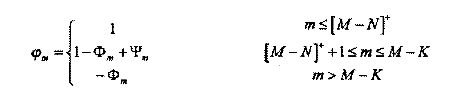
où K est le nombre de sources et par conséquent le nombre de formes d'onde (wa, wb, wc...) reçues au niveau des M unités de réception (1, 2, 3, 4...) et où :
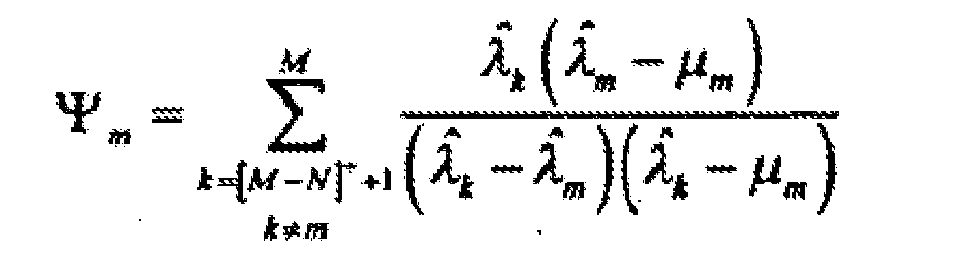
où
- Procédé selon l'une quelconque des revendications précédentes, dans lequel la matrice de corrélation spatiale d'échantillon R̂ prend la forme de :

ou une autre forme quelconque parmi celles connues dans l'art. - Procédé selon la revendication 7 dépendante de la revendication 3, dans lequel l'étape d'identification des K solutions de la fonction de coût est effectuée par sélection des K minima locaux les plus profonds de la fonction de coût suivante :

où f(̂·) est une fonction de valeur réelle croissante, ou par sélection des K maxima locaux les plus élevés de la fonction de coût suivante :
oùg(·) est une fonction de valeur réelle décroissante, et où
- Procédé selon la revendication 7 dans lequel, lorsque les M éléments de réception (1, 2, 3, 4...) forment un réseau linéaire uniforme, le procédé comprend en outre les étapes de :- construction de la matrice
 - construction d'un polynôme
 - choix de z1,...,zK parmi les racines du polynôme complexe D(z), comme étant celles qui réduisent au minimum la quantité f(|D(exp(jarg(zk )))|),
où f(·) est une fonction de valeur réelle croissante, ou maximisent la quantité g(|D(exp(jarg(zk )))|),
où g(·) est une fonction de valeur réelle décroissante,
et où j est l'unité imaginaire, arg(·) désigne l'argument d'un nombre complexe et ∥ désigne le module d'un nombre complexe ;- obtention, parmi ces z1, ..., zK, les K directions d'arrivée estimées :
où d désigne la distance entre les éléments du réseau et λ est la longueur d'onde des formes d'onde incidentes. - Procédé selon la revendication 7 dépendante de la revendication 3, dans lequel, lorsque les M éléments de réception (1, 2, 3, 4...) forment un réseau linéaire uniforme, le procédé comprend en outre les étapes de :- division du réseau de M éléments en Mss sous-réseaux plus petits, chacun contenant L éléments de réception, Mss et L étant des nombres entiers naturels ;- division de chacun des N vecteurs de colonne y(1), ..., y(N) en Mss vecteurs de colonne plus petits yMss (1), ..., yMss (N), chacun desdits vecteurs de colonne plus petits ayant L lignes ;- calcul de Mss matrices de corrélation spatiale d'échantillon au niveau de chacun des Mss sous-réseaux plus petits ;- calcul de moyenne desdites Mss matrices de corrélation spatiale d'échantillon et construction d'une matrice de corrélation spatiale LxL moyennée R̂ à partir de celle-ci ;- construction d'un vecteur de colonne ass (θ) par sélection des L premières lignes de a(θ) ;- sélection des K minima locaux les plus profonds de la fonction de coût suivante :

où f(·) est une fonction de valeur réelle croissante,
ou K maxima locaux les plus élevés de la fonction de coût suivante où g(·) est une fonction de valeur réelle décroissante, et
- Procédé selon la revendication 7 dépendante de la revendication 3, dans lequel l'étape d'identification de K solutions d'une fonction de coût est effectuée par sélection de K extrêmes locaux de ladite fonction de coût au moyen d'un procédé de K itérations, où à la k ème itération, k=1... K, le kème extrême local est choisi comme étant le minimum correspondant de la fonction de coût

où f(·) est une fonction de valeur réelle croissante, ou le maximum correspondant de la fonction de coût
où g(·) est une fonction de valeur réelle décroissante, et où

et où θ1,...,θ k-1 sont les extrêmes locaux sélectionnés dans les itérations précédentes et
∥·∥ désigne la norme euclidienne d'un vecteur. - Procédé selon la revendication 7, comprenant en outre l'étape d'augmentation de la résolution de l'algorithme entre des régions sélectionnées de directions d'arrivée, par multiplication des valeurs d'échantillon obtenues au niveau de l'unité de traitement de signal (40) par une matrice Mb xM B, où M<Mb , où les valeurs de la matrice B dépendent de la géométrie du réseau des éléments de réception.
- Procédé selon la revendication 13, dans lequel la matrice de corrélation spatiale d'échantillon R̂ prend la forme de :

et où les directions d'arrivée des signaux d'intérêt sont estimées par sélection des K minima locaux les plus profonds de la fonction de coût
où f(·) est une fonction de valeur réelle croissante, ou sélection des K maxima locaux les plus élevés de la fonction de coût
où g(·) est une fonction de valeur réelle décroissante,
et où
- Procédé selon l'une quelconque des revendications précédentes, dans lequel ladite au moins une forme d'onde de réception (wa) est un signal de radiofréquence ou un signal d'hyperfréquence.
- Système comprenant des moyens adaptés pour conduire les étapes du procédé selon l'une quelconque des revendications précédentes.
- Programme informatique comprenant des moyens de code de programme informatique adaptés pour effectuer les étapes du procédé de l'une quelconque des revendications 1 à 15 lorsque ledit programme est exécuté sur un ordinateur, un processeur de signal numérique, un réseau prédiffusé programmable par l'utilisateur, un circuit intégré spécifique, un microprocesseur, un microcontrôleur, ou une autre forme quelconque de matériel programmable.
Applications Claiming Priority (1)
| Application Number | Priority Date | Filing Date | Title |
|---|---|---|---|
| PCT/EP2006/002167 WO2007101451A1 (fr) | 2006-03-09 | 2006-03-09 | Procédé et système permettant d'estimer des directions d'arrivée dans des scénarios à taille d'échantillon réduite ou faible puissance |
Publications (2)
| Publication Number | Publication Date |
|---|---|
| EP2005207A1 EP2005207A1 (fr) | 2008-12-24 |
| EP2005207B1 true EP2005207B1 (fr) | 2011-07-13 |
Family
ID=37310614
Family Applications (1)
| Application Number | Title | Priority Date | Filing Date |
|---|---|---|---|
| EP06707487A Expired - Lifetime EP2005207B1 (fr) | 2006-03-09 | 2006-03-09 | Procédé et système permettant d'estimer des directions d'arrivée dans des scénarios à taille d'échantillon réduite ou faible puissance |
Country Status (6)
| Country | Link |
|---|---|
| US (1) | US7982670B2 (fr) |
| EP (1) | EP2005207B1 (fr) |
| JP (1) | JP4990919B2 (fr) |
| AT (1) | ATE516508T1 (fr) |
| ES (1) | ES2372531T3 (fr) |
| WO (1) | WO2007101451A1 (fr) |
Cited By (2)
| Publication number | Priority date | Publication date | Assignee | Title |
|---|---|---|---|---|
| CN104035069A (zh) * | 2014-06-18 | 2014-09-10 | 西安交通大学 | 基于部分矫正对称均匀线阵的窄带近场信号源定位方法 |
| CN107728112A (zh) * | 2017-09-29 | 2018-02-23 | 西安电子科技大学 | 在目标导向矢量严重失配情况下的稳健波束形成方法 |
Families Citing this family (21)
| Publication number | Priority date | Publication date | Assignee | Title |
|---|---|---|---|---|
| US8004463B2 (en) * | 2007-11-19 | 2011-08-23 | Raytheon Company | Systems and methods for determining direction-of-arrival |
| US8179319B1 (en) * | 2008-12-17 | 2012-05-15 | L-3 Services, Inc. | Adaptive optimization of estimation of the angle of arrival of a signal received by an array of antenna elements |
| US8964656B2 (en) * | 2009-04-02 | 2015-02-24 | Lg Electronics Inc. | Method of transmitting channel state information in wireless communication system |
| CN102385049A (zh) * | 2011-08-10 | 2012-03-21 | 西安交通大学 | 基于双平行阵列的二维相干信号方向估计方法 |
| JP6028388B2 (ja) * | 2012-05-11 | 2016-11-16 | 富士通株式会社 | 到来方向推定装置、及び到来方向推定方法 |
| CN103901394B (zh) * | 2014-03-21 | 2016-07-06 | 哈尔滨工程大学 | 一种冲击噪声环境下的量子万有引力搜索动态doa估计方法 |
| CN104021293A (zh) * | 2014-06-09 | 2014-09-03 | 哈尔滨工业大学深圳研究生院 | 一种基于结构最小二乘法的联合到达角-频率估计方法 |
| CN104931928B (zh) * | 2015-07-01 | 2017-10-10 | 西北工业大学 | 一种信号源定位方法及装置 |
| JP6369409B2 (ja) * | 2015-07-22 | 2018-08-08 | マツダ株式会社 | エンジンの制御装置 |
| CN107121669B (zh) * | 2016-02-25 | 2021-08-20 | 松下电器(美国)知识产权公司 | 声源探测装置、声源探测方法及非瞬时性记录介质 |
| CN105866730B (zh) * | 2016-03-24 | 2017-12-26 | 合肥工业大学 | 一种基于music算法的谱峰搜索方法及其硬件电路 |
| CN105913044B (zh) * | 2016-05-04 | 2019-05-24 | 大连理工大学 | 一种基于Sigmoid协方差矩阵的多重信号分类方法 |
| CN106443570B (zh) * | 2016-08-22 | 2019-03-29 | 西安电子科技大学 | 基于多重信号分类算法矢量相关性的波达方向估计方法 |
| CN106569171B (zh) * | 2016-11-08 | 2018-11-30 | 西安电子科技大学 | 基于双层混合阵列的波达方向角估计方法 |
| CN106872935B (zh) * | 2017-03-20 | 2019-04-12 | 北京理工大学 | 一种基于四元数的电磁矢量传感器阵列波达方向估计方法 |
| CN108520195B (zh) * | 2018-01-31 | 2020-12-29 | 湖北工业大学 | 一种基于引力搜索算法的music谱峰搜索方法 |
| CN108761380B (zh) * | 2018-05-23 | 2022-05-03 | 西安电子科技大学 | 一种用于提高精度的目标波达方向估计方法 |
| WO2020010257A1 (fr) * | 2018-07-06 | 2020-01-09 | University Of Massachusetts | Estimation de position tridimensionnelle à l'aide d'un traitement multiplicatif de mesures de capteur |
| JP7222952B2 (ja) * | 2020-07-29 | 2023-02-15 | 京セラ株式会社 | 電子機器、電子機器の制御方法、及びプログラム |
| CN113900060B (zh) * | 2021-09-15 | 2024-07-05 | 中国科学院国家空间科学中心 | 一种基于软件无线电设备的doa估计系统及估计方法 |
| CN114609587B (zh) * | 2022-03-16 | 2025-02-07 | 西北工业大学 | 一种导向矢量估计方法及系统 |
Family Cites Families (8)
| Publication number | Priority date | Publication date | Assignee | Title |
|---|---|---|---|---|
| FR2749733B1 (fr) * | 1996-06-07 | 1998-11-27 | Thomson Csf | Procede et dispositif de gestion des transferts intercellulaires des communications dans un systeme de radiocommunication cellulaire |
| JP3233088B2 (ja) * | 1998-01-22 | 2001-11-26 | 松下電器産業株式会社 | 指向性制御アンテナ装置 |
| JP2988463B2 (ja) * | 1998-03-24 | 1999-12-13 | 日本電気株式会社 | 方向探知装置及びそのための測定結果処理装置 |
| US6311043B1 (en) * | 1998-10-27 | 2001-10-30 | Siemens Aktiengesellschaft | Method and measurement configuration for measuring the characteristics of radio channels |
| US6333713B1 (en) * | 1999-08-24 | 2001-12-25 | Matsushita Electric Industrial Co., Ltd. | Direction estimating apparatus, directivity controlling antenna apparatus, and direction estimating method |
| ATE463749T1 (de) * | 2001-04-27 | 2010-04-15 | Mitsubishi Elec R&D Ct Europe | Verfahren zur einfallsrichtungsschätzung |
| JP4339801B2 (ja) * | 2003-05-22 | 2009-10-07 | 富士通株式会社 | 固有値分解を利用しない信号到来方向推定手法および受信ビーム形成装置 |
| EP1637901A4 (fr) * | 2003-06-25 | 2007-12-26 | Fujitsu Ltd | Procede et dispositif permettant d'estimer la direction d'arrivee d'une onde |
-
2006
- 2006-03-09 WO PCT/EP2006/002167 patent/WO2007101451A1/fr not_active Ceased
- 2006-03-09 AT AT06707487T patent/ATE516508T1/de not_active IP Right Cessation
- 2006-03-09 US US12/281,175 patent/US7982670B2/en not_active Expired - Fee Related
- 2006-03-09 EP EP06707487A patent/EP2005207B1/fr not_active Expired - Lifetime
- 2006-03-09 ES ES06707487T patent/ES2372531T3/es not_active Expired - Lifetime
- 2006-03-09 JP JP2008557596A patent/JP4990919B2/ja not_active Expired - Fee Related
Cited By (4)
| Publication number | Priority date | Publication date | Assignee | Title |
|---|---|---|---|---|
| CN104035069A (zh) * | 2014-06-18 | 2014-09-10 | 西安交通大学 | 基于部分矫正对称均匀线阵的窄带近场信号源定位方法 |
| CN104035069B (zh) * | 2014-06-18 | 2016-08-17 | 西安交通大学 | 基于部分矫正对称均匀线阵的窄带近场信号源定位方法 |
| CN107728112A (zh) * | 2017-09-29 | 2018-02-23 | 西安电子科技大学 | 在目标导向矢量严重失配情况下的稳健波束形成方法 |
| CN107728112B (zh) * | 2017-09-29 | 2020-08-14 | 西安电子科技大学 | 在目标导向矢量严重失配情况下的稳健波束形成方法 |
Also Published As
| Publication number | Publication date |
|---|---|
| EP2005207A1 (fr) | 2008-12-24 |
| JP2009529660A (ja) | 2009-08-20 |
| ES2372531T3 (es) | 2012-01-23 |
| US7982670B2 (en) | 2011-07-19 |
| US20090009394A1 (en) | 2009-01-08 |
| ATE516508T1 (de) | 2011-07-15 |
| JP4990919B2 (ja) | 2012-08-01 |
| WO2007101451A1 (fr) | 2007-09-13 |
Similar Documents
| Publication | Publication Date | Title |
|---|---|---|
| EP2005207B1 (fr) | Procédé et système permettant d'estimer des directions d'arrivée dans des scénarios à taille d'échantillon réduite ou faible puissance | |
| US11782118B2 (en) | Direction of arrival estimation | |
| US11592521B1 (en) | Signal detection and denoising systems | |
| Oispuu et al. | Direct detection and position determination of multiple sources with intermittent emission | |
| US20030085832A1 (en) | Digital beamforming radar system and method with super-resolution multiple jammer location | |
| US11269070B2 (en) | Radar apparatus | |
| CN117075031A (zh) | 一种低信噪比s模式信号的协方差累积波达方向估计方法 | |
| Jiang et al. | Robust detection of number of sources using the transformed rotational matrix | |
| Hoang et al. | Low-complexity direction-of-arrival estimation with orthogonal matching pursuit for large-scale lens antenna array | |
| Hoang et al. | Low-complexity compressed sensing-aided coherent direction-of-arrival estimation for large-scale lens antenna array | |
| Vesa et al. | Performances of Uniform Sensor Array Antenna in case of DoA estimation using the MUSIC Algorithm | |
| Kantor et al. | Prior mismatch in Bayesian direction of arrival estimation for sparse arrays | |
| Dakulagi | A new nystrom approximation based efficient coherent doa estimator for radar applications | |
| Wang et al. | Signal and array processing techniques for RFID readers | |
| Ch et al. | Working Performance of DOA Estimation for MUSIC Algorithm with Varying Array Parameters | |
| Ping et al. | Study of 2D DOA estimation for uniform circular array in wireless location system | |
| Tan et al. | Problems with direction finding using linear array with element spacing more than half wavelength | |
| Lee et al. | Performance Analysis of Noise Signal Reduction Using | |
| US12618940B2 (en) | Signal detection and denoising systems | |
| Voicu et al. | Enabling super-resolution for automotive imaging radars in the presence of antenna calibration errors | |
| CN119667598B (zh) | 一种任意阵列结构的声矢量传感器2d-doa估计方法及系统 | |
| Elkasrawi et al. | Direction finding of correlated sources in extremely low SNR environment | |
| Tripathi et al. | DoA Estimation in RIS-Assisted Network via Element Sampling and Sparse Reconstruction | |
| Zhu et al. | Radar detection using array processing | |
| Esmaeilbeig et al. | Real-time Range-Angle Estimation and Tag Localization for Multi-static Backscatter Systems |
Legal Events
| Date | Code | Title | Description |
|---|---|---|---|
| PUAI | Public reference made under article 153(3) epc to a published international application that has entered the european phase |
Free format text: ORIGINAL CODE: 0009012 |
|
| 17P | Request for examination filed |
Effective date: 20081008 |
|
| AK | Designated contracting states |
Kind code of ref document: A1 Designated state(s): AT BE BG CH CY CZ DE DK EE ES FI FR GB GR HU IE IS IT LI LT LU LV MC NL PL PT RO SE SI SK TR |
|
| RIN1 | Information on inventor provided before grant (corrected) |
Inventor name: MESTRE PONS, FRANCESC XAVIERFUNDACIO PRIVADA CENTR |
|
| 17Q | First examination report despatched |
Effective date: 20090525 |
|
| GRAP | Despatch of communication of intention to grant a patent |
Free format text: ORIGINAL CODE: EPIDOSNIGR1 |
|
| DAX | Request for extension of the european patent (deleted) | ||
| GRAS | Grant fee paid |
Free format text: ORIGINAL CODE: EPIDOSNIGR3 |
|
| GRAA | (expected) grant |
Free format text: ORIGINAL CODE: 0009210 |
|
| AK | Designated contracting states |
Kind code of ref document: B1 Designated state(s): AT BE BG CH CY CZ DE DK EE ES FI FR GB GR HU IE IS IT LI LT LU LV MC NL PL PT RO SE SI SK TR |
|
| REG | Reference to a national code |
Ref country code: GB Ref legal event code: FG4D |
|
| REG | Reference to a national code |
Ref country code: CH Ref legal event code: EP |
|
| REG | Reference to a national code |
Ref country code: IE Ref legal event code: FG4D |
|
| REG | Reference to a national code |
Ref country code: DE Ref legal event code: R096 Ref document number: 602006023050 Country of ref document: DE Effective date: 20110901 |
|
| REG | Reference to a national code |
Ref country code: NL Ref legal event code: VDEP Effective date: 20110713 |
|
| REG | Reference to a national code |
Ref country code: AT Ref legal event code: MK05 Ref document number: 516508 Country of ref document: AT Kind code of ref document: T Effective date: 20110713 |
|
| REG | Reference to a national code |
Ref country code: ES Ref legal event code: FG2A Ref document number: 2372531 Country of ref document: ES Kind code of ref document: T3 Effective date: 20120123 |
|
| PG25 | Lapsed in a contracting state [announced via postgrant information from national office to epo] |
Ref country code: FI Free format text: LAPSE BECAUSE OF FAILURE TO SUBMIT A TRANSLATION OF THE DESCRIPTION OR TO PAY THE FEE WITHIN THE PRESCRIBED TIME-LIMIT Effective date: 20110713 Ref country code: BE Free format text: LAPSE BECAUSE OF FAILURE TO SUBMIT A TRANSLATION OF THE DESCRIPTION OR TO PAY THE FEE WITHIN THE PRESCRIBED TIME-LIMIT Effective date: 20110713 Ref country code: PT Free format text: LAPSE BECAUSE OF FAILURE TO SUBMIT A TRANSLATION OF THE DESCRIPTION OR TO PAY THE FEE WITHIN THE PRESCRIBED TIME-LIMIT Effective date: 20111114 Ref country code: NL Free format text: LAPSE BECAUSE OF FAILURE TO SUBMIT A TRANSLATION OF THE DESCRIPTION OR TO PAY THE FEE WITHIN THE PRESCRIBED TIME-LIMIT Effective date: 20110713 Ref country code: LT Free format text: LAPSE BECAUSE OF FAILURE TO SUBMIT A TRANSLATION OF THE DESCRIPTION OR TO PAY THE FEE WITHIN THE PRESCRIBED TIME-LIMIT Effective date: 20110713 Ref country code: SE Free format text: LAPSE BECAUSE OF FAILURE TO SUBMIT A TRANSLATION OF THE DESCRIPTION OR TO PAY THE FEE WITHIN THE PRESCRIBED TIME-LIMIT Effective date: 20110713 Ref country code: IS Free format text: LAPSE BECAUSE OF FAILURE TO SUBMIT A TRANSLATION OF THE DESCRIPTION OR TO PAY THE FEE WITHIN THE PRESCRIBED TIME-LIMIT Effective date: 20111113 |
|
| PG25 | Lapsed in a contracting state [announced via postgrant information from national office to epo] |
Ref country code: CY Free format text: LAPSE BECAUSE OF FAILURE TO SUBMIT A TRANSLATION OF THE DESCRIPTION OR TO PAY THE FEE WITHIN THE PRESCRIBED TIME-LIMIT Effective date: 20110713 Ref country code: AT Free format text: LAPSE BECAUSE OF FAILURE TO SUBMIT A TRANSLATION OF THE DESCRIPTION OR TO PAY THE FEE WITHIN THE PRESCRIBED TIME-LIMIT Effective date: 20110713 Ref country code: SI Free format text: LAPSE BECAUSE OF FAILURE TO SUBMIT A TRANSLATION OF THE DESCRIPTION OR TO PAY THE FEE WITHIN THE PRESCRIBED TIME-LIMIT Effective date: 20110713 Ref country code: GR Free format text: LAPSE BECAUSE OF FAILURE TO SUBMIT A TRANSLATION OF THE DESCRIPTION OR TO PAY THE FEE WITHIN THE PRESCRIBED TIME-LIMIT Effective date: 20111014 Ref country code: PL Free format text: LAPSE BECAUSE OF FAILURE TO SUBMIT A TRANSLATION OF THE DESCRIPTION OR TO PAY THE FEE WITHIN THE PRESCRIBED TIME-LIMIT Effective date: 20110713 Ref country code: LV Free format text: LAPSE BECAUSE OF FAILURE TO SUBMIT A TRANSLATION OF THE DESCRIPTION OR TO PAY THE FEE WITHIN THE PRESCRIBED TIME-LIMIT Effective date: 20110713 |
|
| PG25 | Lapsed in a contracting state [announced via postgrant information from national office to epo] |
Ref country code: SK Free format text: LAPSE BECAUSE OF FAILURE TO SUBMIT A TRANSLATION OF THE DESCRIPTION OR TO PAY THE FEE WITHIN THE PRESCRIBED TIME-LIMIT Effective date: 20110713 Ref country code: CZ Free format text: LAPSE BECAUSE OF FAILURE TO SUBMIT A TRANSLATION OF THE DESCRIPTION OR TO PAY THE FEE WITHIN THE PRESCRIBED TIME-LIMIT Effective date: 20110713 |
|
| PLBE | No opposition filed within time limit |
Free format text: ORIGINAL CODE: 0009261 |
|
| STAA | Information on the status of an ep patent application or granted ep patent |
Free format text: STATUS: NO OPPOSITION FILED WITHIN TIME LIMIT |
|
| PG25 | Lapsed in a contracting state [announced via postgrant information from national office to epo] |
Ref country code: EE Free format text: LAPSE BECAUSE OF FAILURE TO SUBMIT A TRANSLATION OF THE DESCRIPTION OR TO PAY THE FEE WITHIN THE PRESCRIBED TIME-LIMIT Effective date: 20110713 Ref country code: IT Free format text: LAPSE BECAUSE OF FAILURE TO SUBMIT A TRANSLATION OF THE DESCRIPTION OR TO PAY THE FEE WITHIN THE PRESCRIBED TIME-LIMIT Effective date: 20110713 Ref country code: RO Free format text: LAPSE BECAUSE OF FAILURE TO SUBMIT A TRANSLATION OF THE DESCRIPTION OR TO PAY THE FEE WITHIN THE PRESCRIBED TIME-LIMIT Effective date: 20110713 |
|
| 26N | No opposition filed |
Effective date: 20120416 |
|
| PG25 | Lapsed in a contracting state [announced via postgrant information from national office to epo] |
Ref country code: DK Free format text: LAPSE BECAUSE OF FAILURE TO SUBMIT A TRANSLATION OF THE DESCRIPTION OR TO PAY THE FEE WITHIN THE PRESCRIBED TIME-LIMIT Effective date: 20110713 |
|
| REG | Reference to a national code |
Ref country code: DE Ref legal event code: R097 Ref document number: 602006023050 Country of ref document: DE Effective date: 20120416 |
|
| PG25 | Lapsed in a contracting state [announced via postgrant information from national office to epo] |
Ref country code: MC Free format text: LAPSE BECAUSE OF NON-PAYMENT OF DUE FEES Effective date: 20120331 |
|
| REG | Reference to a national code |
Ref country code: CH Ref legal event code: PL |
|
| REG | Reference to a national code |
Ref country code: IE Ref legal event code: MM4A |
|
| PG25 | Lapsed in a contracting state [announced via postgrant information from national office to epo] |
Ref country code: CH Free format text: LAPSE BECAUSE OF NON-PAYMENT OF DUE FEES Effective date: 20120331 Ref country code: IE Free format text: LAPSE BECAUSE OF NON-PAYMENT OF DUE FEES Effective date: 20120309 Ref country code: LI Free format text: LAPSE BECAUSE OF NON-PAYMENT OF DUE FEES Effective date: 20120331 |
|
| PG25 | Lapsed in a contracting state [announced via postgrant information from national office to epo] |
Ref country code: BG Free format text: LAPSE BECAUSE OF FAILURE TO SUBMIT A TRANSLATION OF THE DESCRIPTION OR TO PAY THE FEE WITHIN THE PRESCRIBED TIME-LIMIT Effective date: 20111013 |
|
| PG25 | Lapsed in a contracting state [announced via postgrant information from national office to epo] |
Ref country code: TR Free format text: LAPSE BECAUSE OF FAILURE TO SUBMIT A TRANSLATION OF THE DESCRIPTION OR TO PAY THE FEE WITHIN THE PRESCRIBED TIME-LIMIT Effective date: 20110713 |
|
| PG25 | Lapsed in a contracting state [announced via postgrant information from national office to epo] |
Ref country code: LU Free format text: LAPSE BECAUSE OF NON-PAYMENT OF DUE FEES Effective date: 20120309 |
|
| PG25 | Lapsed in a contracting state [announced via postgrant information from national office to epo] |
Ref country code: HU Free format text: LAPSE BECAUSE OF FAILURE TO SUBMIT A TRANSLATION OF THE DESCRIPTION OR TO PAY THE FEE WITHIN THE PRESCRIBED TIME-LIMIT Effective date: 20060309 |
|
| REG | Reference to a national code |
Ref country code: FR Ref legal event code: PLFP Year of fee payment: 10 |
|
| PGFP | Annual fee paid to national office [announced via postgrant information from national office to epo] |
Ref country code: DE Payment date: 20150324 Year of fee payment: 10 Ref country code: ES Payment date: 20150324 Year of fee payment: 10 |
|
| PGFP | Annual fee paid to national office [announced via postgrant information from national office to epo] |
Ref country code: FR Payment date: 20150317 Year of fee payment: 10 Ref country code: GB Payment date: 20150319 Year of fee payment: 10 |
|
| REG | Reference to a national code |
Ref country code: DE Ref legal event code: R119 Ref document number: 602006023050 Country of ref document: DE |
|
| GBPC | Gb: european patent ceased through non-payment of renewal fee |
Effective date: 20160309 |
|
| REG | Reference to a national code |
Ref country code: FR Ref legal event code: ST Effective date: 20161130 |
|
| PG25 | Lapsed in a contracting state [announced via postgrant information from national office to epo] |
Ref country code: FR Free format text: LAPSE BECAUSE OF NON-PAYMENT OF DUE FEES Effective date: 20160331 Ref country code: GB Free format text: LAPSE BECAUSE OF NON-PAYMENT OF DUE FEES Effective date: 20160309 Ref country code: DE Free format text: LAPSE BECAUSE OF NON-PAYMENT OF DUE FEES Effective date: 20161001 |
|
| PG25 | Lapsed in a contracting state [announced via postgrant information from national office to epo] |
Ref country code: ES Free format text: LAPSE BECAUSE OF NON-PAYMENT OF DUE FEES Effective date: 20160310 |
|
| REG | Reference to a national code |
Ref country code: ES Ref legal event code: FD2A Effective date: 20180627 |