EP2005448B1 - Électro-aimant de levage ainsi que procédé de fabrication dudit électro-aimant - Google Patents
Électro-aimant de levage ainsi que procédé de fabrication dudit électro-aimant Download PDFInfo
- Publication number
- EP2005448B1 EP2005448B1 EP07711610A EP07711610A EP2005448B1 EP 2005448 B1 EP2005448 B1 EP 2005448B1 EP 07711610 A EP07711610 A EP 07711610A EP 07711610 A EP07711610 A EP 07711610A EP 2005448 B1 EP2005448 B1 EP 2005448B1
- Authority
- EP
- European Patent Office
- Prior art keywords
- cone
- disc
- yoke
- armature
- bearing
- Prior art date
- Legal status (The legal status is an assumption and is not a legal conclusion. Google has not performed a legal analysis and makes no representation as to the accuracy of the status listed.)
- Not-in-force
Links
- 238000004519 manufacturing process Methods 0.000 title claims abstract description 29
- 238000000034 method Methods 0.000 title claims description 16
- 230000004907 flux Effects 0.000 claims abstract description 7
- 238000005304 joining Methods 0.000 claims description 11
- 238000003466 welding Methods 0.000 claims description 8
- 238000003780 insertion Methods 0.000 claims description 3
- 230000037431 insertion Effects 0.000 claims description 3
- 238000003825 pressing Methods 0.000 claims description 3
- 230000000284 resting effect Effects 0.000 claims 1
- 230000000712 assembly Effects 0.000 description 6
- 238000000429 assembly Methods 0.000 description 6
- 238000010276 construction Methods 0.000 description 4
- 230000008569 process Effects 0.000 description 3
- 230000005540 biological transmission Effects 0.000 description 2
- 150000001875 compounds Chemical class 0.000 description 2
- 238000009434 installation Methods 0.000 description 2
- 239000000463 material Substances 0.000 description 2
- 230000015572 biosynthetic process Effects 0.000 description 1
- 230000006835 compression Effects 0.000 description 1
- 238000007906 compression Methods 0.000 description 1
- 230000008602 contraction Effects 0.000 description 1
- 230000008878 coupling Effects 0.000 description 1
- 238000010168 coupling process Methods 0.000 description 1
- 238000005859 coupling reaction Methods 0.000 description 1
- 230000001419 dependent effect Effects 0.000 description 1
- 230000007613 environmental effect Effects 0.000 description 1
- 230000006872 improvement Effects 0.000 description 1
- 239000000696 magnetic material Substances 0.000 description 1
- 238000003860 storage Methods 0.000 description 1
- WFKWXMTUELFFGS-UHFFFAOYSA-N tungsten Chemical compound [W] WFKWXMTUELFFGS-UHFFFAOYSA-N 0.000 description 1
- 229910052721 tungsten Inorganic materials 0.000 description 1
- 239000010937 tungsten Substances 0.000 description 1
Images

Classifications
-
- H—ELECTRICITY
- H01—ELECTRIC ELEMENTS
- H01F—MAGNETS; INDUCTANCES; TRANSFORMERS; SELECTION OF MATERIALS FOR THEIR MAGNETIC PROPERTIES
- H01F7/00—Magnets
- H01F7/06—Electromagnets; Actuators including electromagnets
- H01F7/08—Electromagnets; Actuators including electromagnets with armatures
- H01F7/16—Rectilinearly-movable armatures
- H01F7/1607—Armatures entering the winding
-
- H—ELECTRICITY
- H01—ELECTRIC ELEMENTS
- H01F—MAGNETS; INDUCTANCES; TRANSFORMERS; SELECTION OF MATERIALS FOR THEIR MAGNETIC PROPERTIES
- H01F7/00—Magnets
- H01F7/06—Electromagnets; Actuators including electromagnets
- H01F7/08—Electromagnets; Actuators including electromagnets with armatures
- H01F7/081—Magnetic constructions
-
- H—ELECTRICITY
- H01—ELECTRIC ELEMENTS
- H01F—MAGNETS; INDUCTANCES; TRANSFORMERS; SELECTION OF MATERIALS FOR THEIR MAGNETIC PROPERTIES
- H01F7/00—Magnets
- H01F7/06—Electromagnets; Actuators including electromagnets
- H01F7/08—Electromagnets; Actuators including electromagnets with armatures
- H01F7/127—Assembling
Definitions
- the invention relates to a lifting magnet according to the preamble of claim 1 and a manufacturing method of such a magnet according to claim 11.
- Solenoids are actuating magnets with which switching or control functions are made.
- the anchor as an actuator can take any intermediate positions and must hold them even with opposing forces.
- lifting magnets work either pushing or pulling.
- the return to the currentless stroke output position usually takes place by a force acting against the magnetic force compression spring.
- a widely used construction form of lifting magnets is the pot magnet.
- This magnetic construction consists of at least three magnetic components: a cylindrical, hollow magnetic body, which is constructed of pole, yoke and a non-magnetic, flux-carrying housing, is embedded therein an axially extending cylindrical coil body with current-carrying coil, and the cylindrical armature, at its end In the stroke direction, a guide rod is arranged as an actuating element and carries out the lifting movements within the magnet body ( DE 44 39 422 A1 ).
- the pole of the magnetic body is divided into an axial cylindrical region and a radial region for manufacturing reasons. Both areas are either a component ( DE 44 38 158 A1 ), or could for manufacturing reasons also consist of two different components.
- the axial region of the pole which is referred to below as a cone, is essentially a cylindrical body, which is arranged in the opening of the magnetic body. It has, at its end facing the armature, a contraction sloping in the direction of the armature, which are designed in such a way that the lifting force generated by magnetic force is proportional to the applied current in the coil ( DE 44 39 422 A1 ).
- the cylindrical components In its interior, the cylindrical components on a central through hole, which is penetrated by the actuating rod of the armature.
- the radial region of the pole is disk-shaped and provided with a central opening whose axial region is connected to the outer diameter of the cone.
- the radially extending portion of this component has a planar bearing surface which is connected to the end of the bobbin and the housing. Due to the disk-shaped arrangement, this component is referred to below as a cone disk.
- the storage and guidance of the cylindrical armature in the opening of the magnetic body takes place in a bearing sleeve.
- the axially extending portion of the sleeve engages over the cone at its open end.
- the bearing sleeve can be configured as a pot closed on one side or as a tube.
- the yoke of the magnetic body is arranged on the opposite end of the cone of the bobbin. Similar to the conical disk, this disk-shaped component has a central opening which is partially or completely penetrated by the end of the bearing sleeve.
- the component referred to below as a yoke disc has a radial recess or a passage and is in contact with its axial inner region with the bearing sleeve. By contrast, the outer axial region is firmly connected to the flow-guiding housing at this point.
- the individual components of the magnet such as the yoke disc, the housing and the cone disc are individually connected together in a special joining and pressing process and formed into a hollow body according to the prior art.
- the individual components are plugged together and connected at the joints with each other by caulking.
- a large game is required, which leads to large concentricity deviations during caulking ( DE 102 38 840 A1 ).
- a manufacturing method for a solenoid is known in which individual components of the magnet are summarized prior to final assembly in advance to form several modules. The individual assemblies are then assembled into a finished magnet.
- the armature is first equipped with the actuating rod and inserted into the guide sleeve or in the guide tube in.
- the guide diameter of the armature and the sleeve or of the tube are manufactured in one clamping in order to keep concentricity deviations minimal.
- the cylindrical cone is inserted into the bearing / guide sleeve and firmly connected at its optimum position, taking into account the stroke of the armature with the wall of the sleeve or the tube in this position.
- the cartridge-shaped assembly thus formed is then subsequently installed in the hollow body, which constitutes a further assembly formed from the housing with inserted coil, the yoke disc and the cone disc.
- the object is achieved in connection with the preamble device by the characterizing features of claim 1 and manufacture by the characterizing features of claim 11.
- the improvement of the hysteresis is achieved by centering the magnetic flux in the flux-guiding parts of the magnetic body, whereby lateral forces are reduced. It will reach a uniform magnetic air gap around the anchor.
- the guide body (sleeve or tube), stored after installation centrally to the yoke disc and the pole. The individual components can thus be manufactured and assembled with less play.
- the manufacturing method for the magnet is based on the modular system known per se, which consists in first of several components of the magnetic body of individual components form, which can also be used for other applications, and assemble the magnets from given assemblies.
- the yoke disc is placed only loosely during manufacture on the flat surface of the housing end and aligned in this position on the bearing sleeve. Subsequently, the fixation takes place axially on the plane surface of the housing end. As a result, no transverse forces at the connection point that cause the joining process occur at this point.
- the yoke disc can thus be placed in the manufacturing process with very close clearance on the guide sleeve and will be connected in this position with the flat surface of the housing.
- the yoke disc is not pressed into the housing in the production, but only loosely placed on this and the flat surface connected to the housing end.
- the guide sleeve or the guide tube is installed stress-free and centered with the yoke disc.
- the preferred type of joint for connecting the yoke disc to the housing is welding, which offers advantages over caulking of the components.
- the cone disk after the alignment of the yoke disk on the bearing sleeve or on the bearing tube, the cone disk can also be positively and / or positively connected to one another in the same manner, whereby welding is also preferred here as the type of joint.
- the non-positive and / or positive joining of the two modules is advantageously carried out by pressing in, caulking or welding.
- the bearing sleeve is positively and / or positively connected only with the cone, which is positively and / or positively connected to the cone disk. This compound is preferably welded.
- a radial seal is provided between the bearing tube and the bearing sleeve and the cone, which is designed in particular as O-rings. This is the case when the magnet space is tightly filled with oil or gasoline or other medium.
- the housing is advantageously non-positively and / or positively connected with the cone disk.
- This compound which is usually caulked or welded, is particularly advantageous in the design of the magnet when conical disk and cone, so the entire pole, form a single component.
- this component projects radially outward at the open end of the cartridge.
- the pole comprises two separate components - the cylindrical cone and the radially mounted on the cone pole disk -, the junction cone / conical disk is non-positively and / or positively connect with each other.
- the cylindrical cone advantageously has at its end facing the conical disk a radially extending annular elevation, which serves as an axial stop in the introduction of the cone disk on the cone.
- the flux-guiding housing is advantageously designed as a tubular jacket made of a stampable and bendable material.
- the tubular material is rolled around the interior of the magnet.
- the "rolled" jacket and the use of a thin-walled tube is possible as a housing in which the necessary openings for the connecting flange and other components are punched in advance.
- the coil has cams on its plane surface in the axial direction. These press during assembly in the bearing surface of the yoke disc.
- the coil is axially fixed in the "cage" of the housing through the cone disc and yoke disc.
- anchor and the bearing sleeve or the bearing tube form a first assembly, which are joined together to form a cartridge-shaped body.
- the housing with the coil, the conical disk and the yoke disk are combined to form a second assembly and assembled into a cylindrical, hollow-shaped structure.
- the cartridge-shaped structure is then introduced into the coaxial opening of the hollow body and both structures are non-positively and / or positively connected to each other.
- the yoke plate is connected to the housing end prior to insertion of the cartridge into the hollow body.
- the cartridge is only radially centered after insertion into the hollow body in the yoke disc.
- the yoke disc is loosely attached to the cartridge and is guided therein only radially.
- the axial guidance takes place at the opposite end by the stop of the cone with the conical disk.
- the stop on the axial end of the cone is pressed into the cone disk.
- the yoke disc and the cone disc are advantageously aligned during joining to the hollow body with a teaching mandrel.
- the joining to the hollow body takes place in one clamping, wherein the coil is inserted in the clamping.
- the yoke plate in contrast to the method described above, not placed on the "empty" hollow body, but as the last step in the magnet manufacturing, after all other modules are joined, attached to the flat surface of the housing.
- a cartridge formation of the assembly of the guide tube or the guide sleeve and the armature which is inserted in advance in the guide sleeve.
- the anchor When designed as a pipe must be ensured by mounting means that the anchor is secured at its the yoke disc facing the end against falling out.
- a second assembly is formed from the cone and the cone disk.
- the conical disk is pushed onto the outer wall of the cylindrical cone at its end facing away from the armature, where it is positively and / or positively connected.
- the cone has at this end an annular radial elevation. This serves both as centering and as a stop for the cone disk to be introduced.
- the tubular housing On this structure then the tubular housing is placed.
- the third assembly comprises a cylindrical body consisting of the first and second assemblies.
- the assembly guide sleeve or guide tube with anchor (first assembly) is on the cone with cone disk (second assembly) fixed and assembled.
- the housing is placed on the third module and inserted the coil in the housing.
- the yoke disc is placed on the complete third assembly.
- Fig. 1 shows a cross-sectional view of a solenoid in the form of a pot magnet, which is used as an actuator for different valve devices and valve functions.
- the pilot and switching valves used for the application are, for example, made by the solenoid according to the invention.
- the in Fig. 1 shown solenoid also be used in the function as a proportional solenoid, which establishes a proportional relationship between the applied current and the stroke or magnetic force.
- a magnetic flux carrying housing 1 with an embedded therein cylindrical coil body 10 can be seen.
- a current-carrying coil 4 is integrated in the bobbin 10 .
- the power is supplied from the outside via an electrical connection point 11, which is externally attached to the housing 1 via a radial connecting flange 12 .
- the housing 1 forms an outer jacket as environmental protection and consists of a rolled around the interior of the magnet, magnetic material consisting of stamped parts or of a stamped tube. The ends of the shell are connected together in an axially extending connection.
- the magnet of Fig. 1 has at its right end to a yoke disc 7 , which is not pressed at its radial outer region, as usual between the housing 1 , but there initially only loosely rests on this component. It is connected to the planar surface 22 of the housing 1 only in a later manufacturing step.
- the pole of the magnet is arranged, which has a conical disk 2 as a radially extending region, which is connected to the bobbin 10 and a flat surface of the housing 1 arranged there. This is done by attaching with laser or with the help of a TIG welding torch (Tungsten Innert gas welding).
- TIG welding torch Tungsten Innert gas welding
- Fig. 1 shows the normally open position of the lifting armature 6.
- the armature 6 is designed as a cylindrical piston and is movably arranged in a guide and / or bearing sleeve 5 , which is arranged in the opening of the hollow body 14 . Magnetic force causes the armature 6 strokes in the direction of the magnetic pole.
- the right stroke limit for the armature 6 forms the sleeve bottom 18.
- the magnetic space in the bearing sleeve is filled with a medium (oil, gas or similar). So that the medium can flow off during the lifting movement, the armature piston 6 can additionally have two continuous longitudinal bores, as in FIG Fig. 1 is shown.
- a medium oil, gas or similar
- the magnetic pole additionally has an axial region, which is arranged for the most part in the bearing sleeve 5 and is encompassed by it.
- This cylindrical member forms the cone 3, which additionally has a central passage 15 which is penetrated by an actuating rod 8 which is connected at its one end to the armature 6 and the other end, the lifting movement of the armature 6 on an actuator (valve spool o. ⁇ hnl .) transmits for the follower element.
- the bearing of the armature 6 takes place exclusively via the actuating rod 8 at a bearing point 16 in the passage 15 of the cone 3.
- the bearing and guide sleeve 9 is fixed force and / or positive fit only on the cone 3 .
- the cone 3 has at its end facing the armature 6 a control cone 9 (armature counterpart) with contra-sloping contour and a recess 17 , which engages in a correspondingly shaped recess 13 of the armature 6 .
- the contour design directly influences the force - stroke characteristic of the magnet.
- the cone 3 At its end remote from the armature 6 , the cone 3 has an annular elevation 21 , which serves as a centering or stop for the conical disk 2 fastened there, which is non-positive and / or positive-locking axially at its inner diameter with the cone 3 is connected and fixed with its radial surface with the bobbin 10 and the housing 1 .
- the bearing sleeve 5 engages with its sleeve bottom 18 facing the end of the inner diameter of the yoke disc 7. It is only radially aligned with the bearing sleeve 5 . At this point, no positive and / or positive connection is provided.
- the sleeve bottom 18 thus forms the right, axial boundary of the magnet.
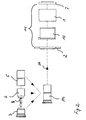
- the magnet can be assembled in two different ways, with both manufacturing methods in common, that the individual components of the magnet are combined into modules and assembled different assemblies to the finished magnet.
- the modular system used in this case is thus suitable for different applications.
- the armature 6 with attached actuating rod 8 and the bearing sleeve 5 to a first assembly summarized.
- the armature 6 is gripped, for example, from a pallet supply, equipped with the actuating rod 8 and inserted into the bearing sleeve 5 .
- the cone 3 is pressed into the bearing sleeve 5 and can be tightly welded with laser or with the TIG welding torch.
- the second assembly forms the hollow body 14, which comprises the cone plate 2, the bobbin 10 with inserted coil 4, the housing 1 and the yoke 7 .
- This is in the right area of the Fig. 2 shown.
- the four components are aligned in a single clamping with a teaching mandrel, initially in the bobbin 10, the coil 4 is inserted and introduced into the housing 1 only.
- These components form a central part of the hollow body 14, whose left end parts of the cone disc 2 and the right end parts of the yoke disc 7 forms. Both components are attached to the central part and connected to each other either by laser or the TIG welding torch to the hollow body 14 .
- the cartridge 19 is loosely inserted to the stop of the annular elevation 21 in the direction of arrow 20 . Both modules are pressed together.
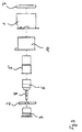
- FIG. 1 An alternative method of manufacturing the magnet Fig. 1 shows Fig. 3 ,
- the armature 6 with actuating rod 8 is inserted into the guide sleeve 5 . Both components together form a first assembly.
- a second assembly is formed from the cone 3 and the conical disk 2 .
- the cone disk 2 is plugged onto the outer wall of the cone 3 up to its annular elevation 21 .
- the axial connection point of the cone 3 with the cone disk 2 is pressed together or welded.
- the two assemblies are then fixed together and put together.
- the housing 1 is placed on the thus formed third assembly.
- the yoke plate 7 is fixed to the bearing sleeve 5 from the right and pressed against the housing surface 22 and welded to this.
- the joint cone / conical disk is aligned together with the yoke disc 7 and non-positively and / or positively connected.
Landscapes
- Physics & Mathematics (AREA)
- Electromagnetism (AREA)
- Engineering & Computer Science (AREA)
- Power Engineering (AREA)
- Magnetically Actuated Valves (AREA)
- Powder Metallurgy (AREA)
- Soft Magnetic Materials (AREA)
- Permanent Magnet Type Synchronous Machine (AREA)
- Manufacturing Of Steel Electrode Plates (AREA)
- Electromagnets (AREA)
Claims (20)
- Électroaimant de levage comprenant un corps d'aimant de forme cylindrique creux, lequel présente un boîtier (1) guidant le flux magnétique dans lequel est logée dans le sens axial une bobine (4) de forme cylindrique conductrice d'électricité, une culasse en forme de disque (disque de culasse 7) et un pôle comportant une zone (cône 3) qui s'étend dans le sens axial ainsi qu'une zone (disque de cône 2) qui s'étend dans le sens radial du cône, un induit (6) cylindrique, logé et guidé dans un manchon support (5) ou dans un tube support, effectuant un mouvement de course axial à l'intérieur du corps d'aimant et le manchon support (5) ou le tube support recouvrant le cône (3) à son extrémité à l'opposé du disque de culasse (7) et, à son autre extrémité, traversant totalement ou partiellement le disque de culasse,
caractérisé en ce que le disque de culasse (7) est aligné de manière amovible avec un faible jeu sur le manchon support ou le tube support et, dans cette position, est relié par adhérence ou par engagement géométrique la surface plane (22) du boîtier (1). - Électroaimant de levage selon la revendication 1, caractérisé en ce que le disque de cône (2) est relié par adhérence et/ou par engagement géométrique au boîtier (1).
- Électroaimant de levage selon la revendication 1 ou 2, caractérisé en ce que le cône (3) est relié par adhérence et/ou par engagement géométrique, notamment soudé, au le manchon support (5) ou le tube support et au disque de cône (2).
- Électroaimant de levage selon l'une des revendications 1 à 3, caractérisé en ce qu'au moins une garniture d'étanchéité radiale, notamment un ou plusieurs joints toriques, est disposée entre le manchon support (5) ou le tube support et le cône (3).
- Électroaimant de levage selon l'une des revendications 1 à 4, caractérisé en ce que le boîtier (1) présente une liaison par adhérence et/ou par engagement géométrique avec le disque de cône (2), en étant notamment maté, emmanché ou soudé.
- Électroaimant de levage selon l'une des revendications 1 à 5, caractérisé en ce que le cône (3) et le disque de cône (2) forment un seul composant.
- Électroaimant de levage selon l'une des revendications 1 à 5, caractérisé en ce que le cône (3) et le disque de cône (2) incluent des composants différents.
- Électroaimant de levage selon l'une des revendications 1 à 7, caractérisé en ce que le cône (3) présente à son extrémité à l'opposé de l'induit un bossage (21) de forme annulaire qui s'étend dans le sens radial et qui fait office de centrage et/ou de butée pour le disque de cône (2) monté.
- Électroaimant de levage selon l'une des revendications 1 à 8, caractérisé en ce que la bobine (4) ou un corps de bobine (10) cylindrique incluant la bobine (4) présente sur les surfaces planes (22) des cames pour la fixation axiale au disque de culasse.
- Électroaimant de levage selon l'une des revendications 1 à 9, caractérisé en ce que le boîtier (1) forme une enveloppe de forme tubulaire, estampée dans le sens axial, pour l'aimant.
- Procédé de fabrication d'un électroaimant de levage selon l'une des revendications 1 à 10, des sous-ensembles constitués de composants individuels du corps d'aimant étant formés et ceux-ci étant assemblés en un aimant,
caractérisé en ce que le disque de culasse (7) est aligné de manière amovible avec un faible jeu sur le manchon support (5) ou le tube support et, dans cette position, est relié par adhérence ou par engagement géométrique avec la surface plane (22) du boîtier (1). - Procédé selon la revendication 11, caractérisé en ce que l'assemblage par adhérence et/ou par engagement géométrique des composants et des sous-ensembles entre eux est réalisé par matage, emmanchement ou soudage.
- Procédé selon l'une des revendications 11 ou 12, le cône (3), l'induit (6) et le manchon support ou le tube support étant assemblés pour former un corps (19) en forme de cartouche, le boîtier (1), le disque de cône (2) et le disque de culasse étant assemblés pour former un corps (14) creux de forme cylindrique, le corps en forme de cartouche (19) état introduit dans l'ouverture coaxiale du corps creux (14) et les deux corps sont reliés l'un à l'autre par adhérence et/ou par engagement géométrique,
caractérisé en ce que le disque de culasse (7) est relié à la surface plane (22) du boîtier avant l'introduction de la cartouche (19) dans le corps creux (14), la cartouche (19) est centrée dans le sens radial dans le disque de culasse (2) après l'introduction dans le corps creux (14), le disque de culasse (7) reposant de manière amovible sur la cartouche (19) et n'étant guidé par celle-ci que dans le sens radial, le guidage axial s'effectuant à l'extrémité opposée par une butée du cône (3) avec le disque de cône (2) et le disque de cône étant fixé par adhérence et par engagement géométrique par le biais de la butée à l'extrémité axiale du cône. - Procédé selon la revendication 13, caractérisé en ce que le cône est fixé dans le manchon support (5) ou le tube support à distance de levage de l'induit.
- Procédé selon la revendication 13 ou 14, caractérisé en ce que la cartouche (19) est emmanchée dans le corps creux (14).
- Procédé selon l'une des revendications 13 à 15, caractérisé en ce que la cartouche (19) est introduite de manière amovible dans le corps creux (14) et fixée au moyen d'une butée axiale qui est disposée sur l'extrémité du cône (3) à l'opposé de l'induit.
- Procédé selon la revendication 15 ou 16, caractérisé en ce que l'assemblage pour former le corps creux (14) s'effectue dans un dispositif de serrage, la bobine étant insérée dans le dispositif de serrage.
- Procédé selon l'une des revendications 13 à 17, caractérisé en ce que le disque de culasse (7) et le disque de cône (2) sont alignés avec un gabarit pendant l'assemblage pour former le corps creux.
- Procédé selon la revendication 11 ou 12, caractérisé par les caractéristiques suivantes :- Formation d'un premier sous-ensemble constitué du manchon support (5) ou du tube support et de l'induit (6) qui a été préalablement introduit dans le manchon (5) ou le tube,- Formation d'un deuxième sous-ensemble constitué du cône (3) et du disque de cône (2) en enfilant et en fixant le disque de cône (2) sur la paroi extérieure du cône (3) au niveau de son extrémité à l'opposé de l'induit,- Fixation et assemblage du premier et du deuxième sous-ensemble sur la paroi extérieure du cône (3) pour former un troisième sous-ensemble,- Montage du boîtier sur le troisième sous-ensemble et insertion de la bobine (4) dans le boîtier (1),- Montage et assemblage du disque de culasse (7) avec le troisième sous-ensemble.
- Procédé selon la revendication 19, caractérisé en ce que le point de liaison entre le cône (3) et le disque de cône (2) est réalisé par adhérence et/ou par engagement géométrique et est aligné conjointement avec le disque de culasse (7).
Applications Claiming Priority (2)
| Application Number | Priority Date | Filing Date | Title |
|---|---|---|---|
| DE102006011078A DE102006011078B4 (de) | 2006-03-08 | 2006-03-08 | Hubmagnet sowie Verfahren zu seiner Herstellung |
| PCT/EP2007/001482 WO2007101550A2 (fr) | 2006-03-08 | 2007-02-21 | Électro-aimant de levage ainsi que procédé de fabrication dudit électro-aimant |
Publications (2)
| Publication Number | Publication Date |
|---|---|
| EP2005448A2 EP2005448A2 (fr) | 2008-12-24 |
| EP2005448B1 true EP2005448B1 (fr) | 2010-09-22 |
Family
ID=38203202
Family Applications (1)
| Application Number | Title | Priority Date | Filing Date |
|---|---|---|---|
| EP07711610A Not-in-force EP2005448B1 (fr) | 2006-03-08 | 2007-02-21 | Électro-aimant de levage ainsi que procédé de fabrication dudit électro-aimant |
Country Status (4)
| Country | Link |
|---|---|
| EP (1) | EP2005448B1 (fr) |
| AT (1) | ATE482457T1 (fr) |
| DE (2) | DE102006011078B4 (fr) |
| WO (1) | WO2007101550A2 (fr) |
Cited By (4)
| Publication number | Priority date | Publication date | Assignee | Title |
|---|---|---|---|---|
| DE102011011362A1 (de) | 2011-02-16 | 2012-08-16 | Thomas Magnete Gmbh | Hysteresearmer Proportionalmagnet |
| DE102011117688B3 (de) * | 2011-11-04 | 2013-03-07 | Thomas Magnete Gmbh | Hysteresearmer Hubmagnet und Verfahren zu seiner Herstellung |
| DE102011115614B4 (de) * | 2011-09-27 | 2014-03-06 | Thomas Magnete Gmbh | Proportionalmagnet |
| DE102014002108A1 (de) | 2014-02-15 | 2015-08-20 | Thomas Magnete Gmbh | Verfahren zur Herstellung eines proportionalwirkenden Elektromagneten und Elektromagnet |
Families Citing this family (10)
| Publication number | Priority date | Publication date | Assignee | Title |
|---|---|---|---|---|
| DE102007043554A1 (de) * | 2007-03-10 | 2008-09-11 | Continental Teves Ag & Co. Ohg | Ventilbaugruppe |
| DE102009043320B4 (de) * | 2009-09-28 | 2012-01-12 | Hydraulik-Ring Gmbh | Elektrohydraulisches Ventil |
| DE102011003169A1 (de) * | 2011-01-26 | 2012-07-26 | Continental Teves Ag & Co. Ohg | Magnetventil |
| DE102012223430A1 (de) | 2012-12-17 | 2014-06-18 | Robert Bosch Gmbh | Elektromagnetisches Stellglied |
| DE102013226619A1 (de) | 2013-12-19 | 2015-06-25 | Robert Bosch Gmbh | Verfahren zur Herstellung eines Polrohrs, Polrohr für einen Elektromagneten und Magnetventil |
| DE102014109575A1 (de) * | 2014-07-09 | 2016-01-14 | Pierburg Gmbh & Co Kg | Elektromagnetventil für den Kfz-Bereich |
| DE102014010876B3 (de) | 2014-07-25 | 2015-10-01 | Hilite Germany Gmbh | Aktuator für ein Hydraulikventil eines Nockenwellenschwenkmotorverstellers und Hydraulikventil mit einem Aktuator für einen Nockenwellenschwenkmotorversteller |
| DE102014113547B4 (de) * | 2014-09-19 | 2022-01-05 | Pierburg Gmbh | Elektromagnetischer Aktor für ein Schubumluftventil |
| DE102017119001A1 (de) * | 2017-08-21 | 2019-02-21 | Kendrion (Villingen) Gmbh | Elektromagnetische Stellvorrichtung |
| DE102019121192A1 (de) * | 2019-08-06 | 2021-02-11 | Rapa Automotive Gmbh & Co. Kg | Leerhubjustage eines magnetaktuators |
Family Cites Families (9)
| Publication number | Priority date | Publication date | Assignee | Title |
|---|---|---|---|---|
| US1650799A (en) * | 1924-05-17 | 1927-11-29 | North East Electric Co | Electric solenoid |
| US3274525A (en) * | 1964-08-28 | 1966-09-20 | Comar Electric Company | Solenoid device having a non-rotatably mounted coil bobbin |
| GB1227087A (fr) * | 1969-07-03 | 1971-03-31 | ||
| DE4438158A1 (de) * | 1993-10-27 | 1995-05-04 | Thomas Magnete Gmbh | Elektro-Hubmagnet |
| US5605318A (en) * | 1994-04-14 | 1997-02-25 | Eaton Corporation | Electric expansion valve |
| DE4439422C2 (de) * | 1994-11-04 | 1996-09-19 | Bso Steuerungstechnik Gmbh | Druckdichte elektromagnetische Schaltvorrichtung |
| JP2002505408A (ja) * | 1998-03-03 | 2002-02-19 | コンティネンタル・テーベス・アクチエンゲゼルシヤフト・ウント・コンパニー・オッフェネ・ハンデルスゲゼルシヤフト | 電磁弁 |
| DE10238840A1 (de) * | 2002-08-23 | 2004-03-04 | Thomas Magnete Gmbh | Magnetanordnung |
| DE102004028871A1 (de) * | 2004-06-15 | 2006-01-05 | Hydac Electronic Gmbh | Betätigungsvorrichtung, insbesondere zum Betätigen von Ventilen |
-
2006
- 2006-03-08 DE DE102006011078A patent/DE102006011078B4/de not_active Expired - Fee Related
-
2007
- 2007-02-21 WO PCT/EP2007/001482 patent/WO2007101550A2/fr not_active Ceased
- 2007-02-21 AT AT07711610T patent/ATE482457T1/de active
- 2007-02-21 EP EP07711610A patent/EP2005448B1/fr not_active Not-in-force
- 2007-02-21 DE DE502007005137T patent/DE502007005137D1/de active Active
Cited By (4)
| Publication number | Priority date | Publication date | Assignee | Title |
|---|---|---|---|---|
| DE102011011362A1 (de) | 2011-02-16 | 2012-08-16 | Thomas Magnete Gmbh | Hysteresearmer Proportionalmagnet |
| DE102011115614B4 (de) * | 2011-09-27 | 2014-03-06 | Thomas Magnete Gmbh | Proportionalmagnet |
| DE102011117688B3 (de) * | 2011-11-04 | 2013-03-07 | Thomas Magnete Gmbh | Hysteresearmer Hubmagnet und Verfahren zu seiner Herstellung |
| DE102014002108A1 (de) | 2014-02-15 | 2015-08-20 | Thomas Magnete Gmbh | Verfahren zur Herstellung eines proportionalwirkenden Elektromagneten und Elektromagnet |
Also Published As
| Publication number | Publication date |
|---|---|
| DE502007005137D1 (de) | 2010-11-04 |
| EP2005448A2 (fr) | 2008-12-24 |
| WO2007101550A2 (fr) | 2007-09-13 |
| DE102006011078B4 (de) | 2011-05-05 |
| WO2007101550A3 (fr) | 2007-12-21 |
| ATE482457T1 (de) | 2010-10-15 |
| DE102006011078A1 (de) | 2007-09-13 |
Similar Documents
| Publication | Publication Date | Title |
|---|---|---|
| EP2005448A2 (fr) | Électro-aimant de levage ainsi que procédé de fabrication dudit électro-aimant | |
| EP2370675B1 (fr) | Unité de commande électromagnétique pour un distributeur hydraulique et procédé de montage de ladite unité | |
| DE102009006355A1 (de) | Proportionalmagnet für ein hydraulisches Wegeventil und Verfahren zu dessen Herstellung | |
| EP2684200B1 (fr) | Actionneur électromagnétique | |
| EP2652376B1 (fr) | Électrovanne | |
| DE102010062096A1 (de) | Linearmagnet | |
| EP2240943A2 (fr) | Aimant de commande | |
| EP2137442A1 (fr) | Soupape électromagnétique et procédé de production | |
| DE4428869C2 (de) | Magnetventil | |
| DE102016224288A1 (de) | Elektromagnetisches Stellglied, Flussscheibenkörper für ein elektromagnetisches Stellglied und Verfahren zur Herstellung eines elektromagnetischen Stellgliedes | |
| DE102008012692A1 (de) | Magnetventilbaugruppe | |
| DE102007033060B4 (de) | Magnetventil mit axial einstellbarem Abstand zwischen Polkern und Rückschlussplatte | |
| DE102018000269A1 (de) | Elektromagnet und Verfahren zur Herstellung des Elektromagneten | |
| DE112021005169T5 (de) | Zylinderspule, Dämpfungskrafteinstellungsmechanismus und Stoßdämpfer mit einstellbarer Dämpfungskraft | |
| EP1878030B1 (fr) | Soupape a cartouche electropneumatique, utilisee en particulier comme soupape pilote avec une soupape pneumatique de structure etroite pour former une unite a soupapes compacte | |
| EP1386332B1 (fr) | Systeme de regulation electromagnetique | |
| DE10301651A1 (de) | Kraftstoffeinspritzvorrichtung mit einem Magnetkreis zum Antreiben eines bewegbaren Kerns | |
| DE102011011362B4 (de) | Hysteresearmer Proportionalmagnet | |
| EP0552416A1 (fr) | Electro-aimant de commande à courant continu | |
| DE102008061414B4 (de) | Verfahren zum Herstellen einer elektromagnetischen Betätigungsvorrichtung, insbesondere zum Betätigen von Ventilen, sowie nach dem Verfahren hergestellte Betätigungsvorrichtung | |
| DE19908440A1 (de) | Wegesitzventil | |
| EP4449456A1 (fr) | Dispositif électromagnétique et procédé de fabrication d'un tel dispositif électromagnétique | |
| DE102011112755B4 (de) | Elektro-Magnet, Verfahren zur Herstellung eines Elektro-Magneten und dessen Verwendung, Ventil mit einem Elektromagneten und dessen Verwendung sowie Luftfahrzeug | |
| EP3070721B1 (fr) | Dispositif d'actionnement | |
| EP0859380A2 (fr) | Electro-aimant de commande à double effet |
Legal Events
| Date | Code | Title | Description |
|---|---|---|---|
| PUAI | Public reference made under article 153(3) epc to a published international application that has entered the european phase |
Free format text: ORIGINAL CODE: 0009012 |
|
| AK | Designated contracting states |
Kind code of ref document: A2 Designated state(s): AT BE BG CH CY CZ DE DK EE ES FI FR GB GR HU IE IS IT LI LT LU LV MC NL PL PT RO SE SI SK TR |
|
| 17P | Request for examination filed |
Effective date: 20080821 |
|
| GRAP | Despatch of communication of intention to grant a patent |
Free format text: ORIGINAL CODE: EPIDOSNIGR1 |
|
| GRAS | Grant fee paid |
Free format text: ORIGINAL CODE: EPIDOSNIGR3 |
|
| GRAA | (expected) grant |
Free format text: ORIGINAL CODE: 0009210 |
|
| AK | Designated contracting states |
Kind code of ref document: B1 Designated state(s): AT BE BG CH CY CZ DE DK EE ES FI FR GB GR HU IE IS IT LI LT LU LV MC NL PL PT RO SE SI SK TR |
|
| REG | Reference to a national code |
Ref country code: GB Ref legal event code: FG4D Free format text: NOT ENGLISH |
|
| REG | Reference to a national code |
Ref country code: CH Ref legal event code: EP |
|
| REG | Reference to a national code |
Ref country code: IE Ref legal event code: FG4D Free format text: LANGUAGE OF EP DOCUMENT: GERMAN |
|
| REF | Corresponds to: |
Ref document number: 502007005137 Country of ref document: DE Date of ref document: 20101104 Kind code of ref document: P |
|
| PG25 | Lapsed in a contracting state [announced via postgrant information from national office to epo] |
Ref country code: LT Free format text: LAPSE BECAUSE OF FAILURE TO SUBMIT A TRANSLATION OF THE DESCRIPTION OR TO PAY THE FEE WITHIN THE PRESCRIBED TIME-LIMIT Effective date: 20100922 Ref country code: FI Free format text: LAPSE BECAUSE OF FAILURE TO SUBMIT A TRANSLATION OF THE DESCRIPTION OR TO PAY THE FEE WITHIN THE PRESCRIBED TIME-LIMIT Effective date: 20100922 |
|
| REG | Reference to a national code |
Ref country code: NL Ref legal event code: VDEP Effective date: 20100922 |
|
| LTIE | Lt: invalidation of european patent or patent extension |
Effective date: 20100922 |
|
| PG25 | Lapsed in a contracting state [announced via postgrant information from national office to epo] |
Ref country code: PL Free format text: LAPSE BECAUSE OF FAILURE TO SUBMIT A TRANSLATION OF THE DESCRIPTION OR TO PAY THE FEE WITHIN THE PRESCRIBED TIME-LIMIT Effective date: 20100922 Ref country code: SI Free format text: LAPSE BECAUSE OF FAILURE TO SUBMIT A TRANSLATION OF THE DESCRIPTION OR TO PAY THE FEE WITHIN THE PRESCRIBED TIME-LIMIT Effective date: 20100922 |
|
| PG25 | Lapsed in a contracting state [announced via postgrant information from national office to epo] |
Ref country code: GR Free format text: LAPSE BECAUSE OF FAILURE TO SUBMIT A TRANSLATION OF THE DESCRIPTION OR TO PAY THE FEE WITHIN THE PRESCRIBED TIME-LIMIT Effective date: 20101223 Ref country code: LV Free format text: LAPSE BECAUSE OF FAILURE TO SUBMIT A TRANSLATION OF THE DESCRIPTION OR TO PAY THE FEE WITHIN THE PRESCRIBED TIME-LIMIT Effective date: 20100922 Ref country code: SE Free format text: LAPSE BECAUSE OF FAILURE TO SUBMIT A TRANSLATION OF THE DESCRIPTION OR TO PAY THE FEE WITHIN THE PRESCRIBED TIME-LIMIT Effective date: 20100922 |
|
| REG | Reference to a national code |
Ref country code: IE Ref legal event code: FD4D |
|
| PG25 | Lapsed in a contracting state [announced via postgrant information from national office to epo] |
Ref country code: IE Free format text: LAPSE BECAUSE OF FAILURE TO SUBMIT A TRANSLATION OF THE DESCRIPTION OR TO PAY THE FEE WITHIN THE PRESCRIBED TIME-LIMIT Effective date: 20100922 |
|
| PG25 | Lapsed in a contracting state [announced via postgrant information from national office to epo] |
Ref country code: PT Free format text: LAPSE BECAUSE OF FAILURE TO SUBMIT A TRANSLATION OF THE DESCRIPTION OR TO PAY THE FEE WITHIN THE PRESCRIBED TIME-LIMIT Effective date: 20110124 Ref country code: SK Free format text: LAPSE BECAUSE OF FAILURE TO SUBMIT A TRANSLATION OF THE DESCRIPTION OR TO PAY THE FEE WITHIN THE PRESCRIBED TIME-LIMIT Effective date: 20100922 Ref country code: IT Free format text: LAPSE BECAUSE OF FAILURE TO SUBMIT A TRANSLATION OF THE DESCRIPTION OR TO PAY THE FEE WITHIN THE PRESCRIBED TIME-LIMIT Effective date: 20100922 Ref country code: EE Free format text: LAPSE BECAUSE OF FAILURE TO SUBMIT A TRANSLATION OF THE DESCRIPTION OR TO PAY THE FEE WITHIN THE PRESCRIBED TIME-LIMIT Effective date: 20100922 Ref country code: CZ Free format text: LAPSE BECAUSE OF FAILURE TO SUBMIT A TRANSLATION OF THE DESCRIPTION OR TO PAY THE FEE WITHIN THE PRESCRIBED TIME-LIMIT Effective date: 20100922 Ref country code: RO Free format text: LAPSE BECAUSE OF FAILURE TO SUBMIT A TRANSLATION OF THE DESCRIPTION OR TO PAY THE FEE WITHIN THE PRESCRIBED TIME-LIMIT Effective date: 20100922 Ref country code: IS Free format text: LAPSE BECAUSE OF FAILURE TO SUBMIT A TRANSLATION OF THE DESCRIPTION OR TO PAY THE FEE WITHIN THE PRESCRIBED TIME-LIMIT Effective date: 20110122 Ref country code: NL Free format text: LAPSE BECAUSE OF FAILURE TO SUBMIT A TRANSLATION OF THE DESCRIPTION OR TO PAY THE FEE WITHIN THE PRESCRIBED TIME-LIMIT Effective date: 20100922 |
|
| PG25 | Lapsed in a contracting state [announced via postgrant information from national office to epo] |
Ref country code: ES Free format text: LAPSE BECAUSE OF FAILURE TO SUBMIT A TRANSLATION OF THE DESCRIPTION OR TO PAY THE FEE WITHIN THE PRESCRIBED TIME-LIMIT Effective date: 20110102 |
|
| PLBE | No opposition filed within time limit |
Free format text: ORIGINAL CODE: 0009261 |
|
| STAA | Information on the status of an ep patent application or granted ep patent |
Free format text: STATUS: NO OPPOSITION FILED WITHIN TIME LIMIT |
|
| 26N | No opposition filed |
Effective date: 20110623 |
|
| BERE | Be: lapsed |
Owner name: THOMAS MAGNETE G.M.B.H. Effective date: 20110228 |
|
| PG25 | Lapsed in a contracting state [announced via postgrant information from national office to epo] |
Ref country code: DK Free format text: LAPSE BECAUSE OF FAILURE TO SUBMIT A TRANSLATION OF THE DESCRIPTION OR TO PAY THE FEE WITHIN THE PRESCRIBED TIME-LIMIT Effective date: 20100922 |
|
| PG25 | Lapsed in a contracting state [announced via postgrant information from national office to epo] |
Ref country code: MC Free format text: LAPSE BECAUSE OF NON-PAYMENT OF DUE FEES Effective date: 20110228 |
|
| REG | Reference to a national code |
Ref country code: CH Ref legal event code: PL |
|
| REG | Reference to a national code |
Ref country code: DE Ref legal event code: R097 Ref document number: 502007005137 Country of ref document: DE Effective date: 20110623 |
|
| PG25 | Lapsed in a contracting state [announced via postgrant information from national office to epo] |
Ref country code: LI Free format text: LAPSE BECAUSE OF NON-PAYMENT OF DUE FEES Effective date: 20110228 Ref country code: CH Free format text: LAPSE BECAUSE OF NON-PAYMENT OF DUE FEES Effective date: 20110228 |
|
| PG25 | Lapsed in a contracting state [announced via postgrant information from national office to epo] |
Ref country code: BE Free format text: LAPSE BECAUSE OF NON-PAYMENT OF DUE FEES Effective date: 20110228 |
|
| REG | Reference to a national code |
Ref country code: AT Ref legal event code: MM01 Ref document number: 482457 Country of ref document: AT Kind code of ref document: T Effective date: 20120221 |
|
| PG25 | Lapsed in a contracting state [announced via postgrant information from national office to epo] |
Ref country code: CY Free format text: LAPSE BECAUSE OF FAILURE TO SUBMIT A TRANSLATION OF THE DESCRIPTION OR TO PAY THE FEE WITHIN THE PRESCRIBED TIME-LIMIT Effective date: 20100922 Ref country code: LU Free format text: LAPSE BECAUSE OF NON-PAYMENT OF DUE FEES Effective date: 20110221 |
|
| PG25 | Lapsed in a contracting state [announced via postgrant information from national office to epo] |
Ref country code: AT Free format text: LAPSE BECAUSE OF NON-PAYMENT OF DUE FEES Effective date: 20120221 |
|
| PG25 | Lapsed in a contracting state [announced via postgrant information from national office to epo] |
Ref country code: TR Free format text: LAPSE BECAUSE OF FAILURE TO SUBMIT A TRANSLATION OF THE DESCRIPTION OR TO PAY THE FEE WITHIN THE PRESCRIBED TIME-LIMIT Effective date: 20100922 Ref country code: BG Free format text: LAPSE BECAUSE OF FAILURE TO SUBMIT A TRANSLATION OF THE DESCRIPTION OR TO PAY THE FEE WITHIN THE PRESCRIBED TIME-LIMIT Effective date: 20101222 |
|
| PG25 | Lapsed in a contracting state [announced via postgrant information from national office to epo] |
Ref country code: HU Free format text: LAPSE BECAUSE OF FAILURE TO SUBMIT A TRANSLATION OF THE DESCRIPTION OR TO PAY THE FEE WITHIN THE PRESCRIBED TIME-LIMIT Effective date: 20100922 |
|
| REG | Reference to a national code |
Ref country code: FR Ref legal event code: PLFP Year of fee payment: 10 |
|
| REG | Reference to a national code |
Ref country code: FR Ref legal event code: PLFP Year of fee payment: 11 |
|
| REG | Reference to a national code |
Ref country code: FR Ref legal event code: PLFP Year of fee payment: 12 |
|
| PGFP | Annual fee paid to national office [announced via postgrant information from national office to epo] |
Ref country code: FR Payment date: 20210217 Year of fee payment: 15 |
|
| PGFP | Annual fee paid to national office [announced via postgrant information from national office to epo] |
Ref country code: DE Payment date: 20210228 Year of fee payment: 15 Ref country code: GB Payment date: 20210222 Year of fee payment: 15 |
|
| REG | Reference to a national code |
Ref country code: DE Ref legal event code: R119 Ref document number: 502007005137 Country of ref document: DE |
|
| GBPC | Gb: european patent ceased through non-payment of renewal fee |
Effective date: 20220221 |
|
| PG25 | Lapsed in a contracting state [announced via postgrant information from national office to epo] |
Ref country code: FR Free format text: LAPSE BECAUSE OF NON-PAYMENT OF DUE FEES Effective date: 20220228 |
|
| PG25 | Lapsed in a contracting state [announced via postgrant information from national office to epo] |
Ref country code: GB Free format text: LAPSE BECAUSE OF NON-PAYMENT OF DUE FEES Effective date: 20220221 Ref country code: DE Free format text: LAPSE BECAUSE OF NON-PAYMENT OF DUE FEES Effective date: 20220901 |