EP2005486B1 - Dispositif de connexion électrique pour conducteurs plats - Google Patents
Dispositif de connexion électrique pour conducteurs plats Download PDFInfo
- Publication number
- EP2005486B1 EP2005486B1 EP07727777A EP07727777A EP2005486B1 EP 2005486 B1 EP2005486 B1 EP 2005486B1 EP 07727777 A EP07727777 A EP 07727777A EP 07727777 A EP07727777 A EP 07727777A EP 2005486 B1 EP2005486 B1 EP 2005486B1
- Authority
- EP
- European Patent Office
- Prior art keywords
- connecting device
- housing
- mounting
- webs
- flat conductor
- Prior art date
- Legal status (The legal status is an assumption and is not a legal conclusion. Google has not performed a legal analysis and makes no representation as to the accuracy of the status listed.)
- Not-in-force
Links
Images


Classifications
-
- H—ELECTRICITY
- H01—ELECTRIC ELEMENTS
- H01R—ELECTRICALLY-CONDUCTIVE CONNECTIONS; STRUCTURAL ASSOCIATIONS OF A PLURALITY OF MUTUALLY-INSULATED ELECTRICAL CONNECTING ELEMENTS; COUPLING DEVICES; CURRENT COLLECTORS
- H01R9/00—Structural associations of a plurality of mutually-insulated electrical connecting elements, e.g. terminal strips or terminal blocks; Terminals or binding posts mounted upon a base or in a case; Bases therefor
- H01R9/22—Bases, e.g. strip, block, panel
-
- H—ELECTRICITY
- H02—GENERATION; CONVERSION OR DISTRIBUTION OF ELECTRIC POWER
- H02S—GENERATION OF ELECTRIC POWER BY CONVERSION OF INFRARED RADIATION, VISIBLE LIGHT OR ULTRAVIOLET LIGHT, e.g. USING PHOTOVOLTAIC [PV] MODULES
- H02S40/00—Components or accessories in combination with PV modules, not provided for in groups H02S10/00 - H02S30/00
- H02S40/30—Electrical components
- H02S40/34—Electrical components comprising specially adapted electrical connection means to be structurally associated with the PV module, e.g. junction boxes
-
- H—ELECTRICITY
- H10—SEMICONDUCTOR DEVICES; ELECTRIC SOLID-STATE DEVICES NOT OTHERWISE PROVIDED FOR
- H10F—INORGANIC SEMICONDUCTOR DEVICES SENSITIVE TO INFRARED RADIATION, LIGHT, ELECTROMAGNETIC RADIATION OF SHORTER WAVELENGTH OR CORPUSCULAR RADIATION
- H10F77/00—Constructional details of devices covered by this subclass
- H10F77/93—Interconnections
- H10F77/933—Interconnections for devices having potential barriers
- H10F77/935—Interconnections for devices having potential barriers for photovoltaic devices or modules
- H10F77/939—Output lead wires or elements
-
- H—ELECTRICITY
- H01—ELECTRIC ELEMENTS
- H01R—ELECTRICALLY-CONDUCTIVE CONNECTIONS; STRUCTURAL ASSOCIATIONS OF A PLURALITY OF MUTUALLY-INSULATED ELECTRICAL CONNECTING ELEMENTS; COUPLING DEVICES; CURRENT COLLECTORS
- H01R4/00—Electrically-conductive connections between two or more conductive members in direct contact, i.e. touching one another; Means for effecting or maintaining such contact; Electrically-conductive connections having two or more spaced connecting locations for conductors and using contact members penetrating insulation
- H01R4/28—Clamped connections, spring connections
- H01R4/48—Clamped connections, spring connections utilising a spring, clip, or other resilient member
- H01R4/4809—Clamped connections, spring connections utilising a spring, clip, or other resilient member using a leaf spring to bias the conductor toward the busbar
- H01R4/48185—Clamped connections, spring connections utilising a spring, clip, or other resilient member using a leaf spring to bias the conductor toward the busbar adapted for axial insertion of a wire end
- H01R4/4819—Clamped connections, spring connections utilising a spring, clip, or other resilient member using a leaf spring to bias the conductor toward the busbar adapted for axial insertion of a wire end the spring shape allowing insertion of the conductor end when the spring is unbiased
- H01R4/4821—Single-blade spring
-
- H—ELECTRICITY
- H01—ELECTRIC ELEMENTS
- H01R—ELECTRICALLY-CONDUCTIVE CONNECTIONS; STRUCTURAL ASSOCIATIONS OF A PLURALITY OF MUTUALLY-INSULATED ELECTRICAL CONNECTING ELEMENTS; COUPLING DEVICES; CURRENT COLLECTORS
- H01R4/00—Electrically-conductive connections between two or more conductive members in direct contact, i.e. touching one another; Means for effecting or maintaining such contact; Electrically-conductive connections having two or more spaced connecting locations for conductors and using contact members penetrating insulation
- H01R4/28—Clamped connections, spring connections
- H01R4/48—Clamped connections, spring connections utilising a spring, clip, or other resilient member
- H01R4/4809—Clamped connections, spring connections utilising a spring, clip, or other resilient member using a leaf spring to bias the conductor toward the busbar
- H01R4/4846—Busbar details
- H01R4/4848—Busbar integrally formed with the spring
-
- Y—GENERAL TAGGING OF NEW TECHNOLOGICAL DEVELOPMENTS; GENERAL TAGGING OF CROSS-SECTIONAL TECHNOLOGIES SPANNING OVER SEVERAL SECTIONS OF THE IPC; TECHNICAL SUBJECTS COVERED BY FORMER USPC CROSS-REFERENCE ART COLLECTIONS [XRACs] AND DIGESTS
- Y02—TECHNOLOGIES OR APPLICATIONS FOR MITIGATION OR ADAPTATION AGAINST CLIMATE CHANGE
- Y02E—REDUCTION OF GREENHOUSE GAS [GHG] EMISSIONS, RELATED TO ENERGY GENERATION, TRANSMISSION OR DISTRIBUTION
- Y02E10/00—Energy generation through renewable energy sources
- Y02E10/50—Photovoltaic [PV] energy
Definitions
- the invention relates to a connection device for conductor ends, in particular blade contacts, to photovoltaic systems according to the preamble of claim 1.
- Photovoltaic systems usually have at least one photovoltaic panel for generating electricity from sunlight.
- flexible flat conductors are usually led out of the photovoltaic panels, which make it possible to connect the photovoltaic panels-as a rule via a multi-conductor cable-for example to a domestic installation or firstly to electrical appliances such as an inverter or the like.
- connection devices with a receiving housing for the flat conductor ends, with which the conductor ends are contacted ( DE 20 2005 018 884 U1 ).
- the prior art are also the US 4,460,232 and the DE 203 11 183 U1 called.
- connection device or a connection device for flat conductors with the simpler way than in the prior art, a contacting of the leads and their. Connection to a higher-level device or system is feasible.
- Claim 1 describes a connection device for conductor ends, in particular flat conductor ends on a photovoltaic panel, from which protrudes a plurality of flat conductor ends, and having a receiving or connection housing, characterized by a mountable on the photovoltaic panel, in particular alsklebbare receiving unit for receiving the flat conductor ends, to which the receiving housing can be placed.
- the flat conductor ends are determined in the manner of a first assembly step or a pre-assembly of the receiving unit, which is then easier to contact as a preassembled unit than the known solutions according to the prior art.
- the receiving unit is designed as a recording medium, which has at least one receptacle or a plurality of receptacles, in particular receiving webs, via which in each case one of the flat conductor ends is bendable.
- the receiving housing attachable to the recording medium, e.g. is latched
- the receiving unit preferably has receptacles, in particular receiving webs, over which or on each of which one of the flat conductor ends can be fixed in a bendable manner.
- This setting is done on the receiving webs, so that from the parent unit from the flat conductor ends on the receiving webs and the recording medium quasi a kind of plug as part of the connecting device and the connecting device is formed directly on the photovoltaic panel.
- the receiving webs may be made of plastic or another, possibly also conductive material, if between the flat conductor ends a possibly required galvanic Separation is realized.
- a possibly required galvanic Separation is realized in the area of each receiving web are thus from the flat conductor ends on the receiving webs stable contacts that are readily insertable against larger forces, for example in a spring contact (especially in push-in technology).
- this preassemblable unit which preferably has a partially open bottom side, so that it can be placed over the receiving carrier.
- This housing also preferably forms part of the unit that can be preassembled on the roof prior to assembly, so that only the photovoltaic panel with the box as a whole can be prefabricated and preassembled, for example, to an inverter on the roof.
- the invention considerably simplifies the connection of photovoltaic panels to higher-level installation systems.
- the connection can be done faster and after a particularly preferred variant even without tools.
- the time required is reduced significantly, as is the risk of incorrect installation.
- the clear and almost self-explanatory installation also makes it easier to maintain and maintain the system.
- the receiving webs can be aligned with one another or offset from one another. It is also conceivable to arrange them all parallel to one another, in particular in a single row, since in this way a particularly narrow but for a somewhat longer connection device can be realized.
- the invention also provides a connecting device for conductor ends, in particular flat conductor ends on a photovoltaic panel from which protrudes a plurality of flat conductor ends, and which has a receiving housing which can be attached to the photovoltaic panel, in particular connecting device according to one of the preceding claims, wherein the Receiving housing has a trough, which is closed except for openings for cable bushings for cables and up to the photovoltaic panel facing side.
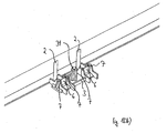
- Fig. 1 shows a photovoltaic panel 1 from which protrudes a plurality of preferably flexible, flexible flat conductor ends 2, which are aligned parallel to each other in a row and whose end portions of the photovoltaic panel 1 are bent vertically upwards.
- connection device This is done on or by means of a recording medium 3 for the conductor ends 2. This is preferably attached easily and quickly by means of a double-sided adhesive tape on the back of the photovoltaic panel.
- the recording medium 3 has a series of receiving webs 6, which are preferably aligned in the mounted state perpendicular to the surface of the photovoltaic panel and over each of the flat conductor ends 2 is bendable to form on the receiving webs 6 stable contact areas.
- the receiving webs 6 are each bounded on both sides by partitions 7, which are aligned perpendicular to the receiving webs 6, so that the receiving webs 6 are clearly separated from each other for the individual flat conductor ends 2, which makes it possible to avoid faulty circuits.
- the receiving webs 6 may be made of plastic or other material, possibly also metal. They can theoretically be oriented almost arbitrarily relative to each other, so in one or more rows next to each other or parallel to each other or, for example, such that they lie together on a sheet.
- the flat conductor ends are inserted through a slot 8 and an elongated recess of the recording medium 3 ( Fig. 2b ) and then each bent over the associated receiving webs 6 (Fig. 2c). This is easy and fast to implement.
- the slot 8 is divided by a stabilizing web 9 into two sections.
- Vorzentrianssstege 13 are formed, which ensure a pre-centering and guiding of the receiving housing when placed on the recording medium and thus serve as a false plug protection.
- An optional longitudinal web 10 opposite the receiving webs 6 can be used for holding and facilitates handling.
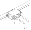
- connection or receiving housing 4 with a plurality of spring terminal strips 5 - here in more advantageous than busbars with terminal contacts in direct plug technology (push-in) formed - can be placed, in particular plugged.
- the receiving housing 4 is - see also Fig. 4 - Multi-part with base 11 and cover part 12 formed on and has - here on the sides - bushings 14, which are suitable for example for the passage of cables - in particular with a PG gland.
- plug-in devices 15 can also be realized here, which can be used for connecting cables with corresponding couplings or directly for connecting further receiving housings.
- Base 11 and cover part 12 may be pivotally connected to one another and locked together to close (see Fig. 4 ).
- a transparent design is conceivable - even in subareas.
- each receiving chamber 27 has at least one recess 28.
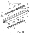
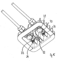
- the connecting rails (arrangements) 17 each comprise a base rail 18 which is U-shaped in cross-section and a cover rail 19 inserted in the latter (cf. Fig. 2 and in terms of the installation situation too Fig. 4 ).
- the base rail 18 and the cover rail 19 each have in the assembled state largely aligned window-like openings 20, 21, from which webs 22, 23 are bent such that the webs 22, 23 of the base rail 18 and the cover rail 19 in the assembled state in their interaction each tulip-like open spring contacts 24 form.
- At each connection rail 17 such a plurality of spring contacts 24 is formed.
- the spring contacts 24 form such a push-in element.
- Each connection rail 24 has further lateral connection contacts 29, which can be used as desired, thus for contacting a line.
- the cover rail 19 engages behind the base rail 18 and is secured thereto.
- a plurality of terminal strips 17 designed as spring terminal strips 5 is used, wherein the number of connecting rails 17 preferably corresponds to the number of flat conductor ends 2 to be contacted.
- the spring terminal strips 5 are aligned parallel to each other.
- each of the openings 20a, 21a is adapted to the contour of the receiving carrier 3, so that the receiving webs 6 with the bent flat conductor ends 2 and the partitions 7 respectively in these openings 20a, 21a of the adjacent connecting rails 17 are inserted, wherein each one of the spring contacts 24a one of the flat conductor ends 2 contacted on the receiving webs 6.
- the further spring contacts 24 can be used to connect components such as diodes 26 ( Fig. 4 ).
- connection box on the photovoltaic panel it is first necessary to bend the flat conductor ends 2 onto the receiving webs 6 of the receiving carrier 3 (by hand or, for example, with pliers) and then to set up the otherwise preassembled receiving housing 4. Then, the terminal housing 4 can be connected by means of plug devices 15 with a higher-level circuit. A direct insertion of the flat conductor ends in the terminal housing or the spring contacts provided there is not possible due to the large spring forces and therefore does not appear to make sense.
- connection and receiving housing 4 On the bottom side 16 of the connection and receiving housing 4, a seal may be provided, which the entire contact area to the photovoltaic panel out seals (not shown here).
- the entire terminal housing 4 can be connected to the photovoltaic panel, for example by screwing or clamping.
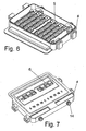
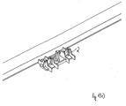
- Fig. 5-9 show views of a further connection device with the terminal housing 4 and the receiving media 3, wherein the recording medium 3 of the Fig. 5-9 Receiving webs 6, which are not in a row but offset from each other ( Fig. 7).
- Fig. 6 shows the terminal housing 4 without cover in a view from above and Fig. 7 the arrangement Fig. 6 from below (ie the side resting on the back of the collector).
- the bushings 14 can be distributed arbitrarily on the remaining pages.
- a breathable membrane for dissipating moisture from the connection housing or the connection box can be realized at an opening (not shown here).
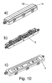
- Fig. 10 and 11 are the housing 4 with the cover 12 and the recording medium 3 with more spaced apart receiving webs 6 are formed such that the spring terminal strips 5 - are aligned here - arranged in a row, so that there is a particularly narrow and long design.
- the diodes 26th are the diodes 26th
- the bushings 14 are preferably arranged on the narrow sides of the elongated terminal housing 4 for realizing a particularly compact design.
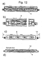
- Fig. 13a - e illustrate the assembly of another connecting device with a receiving housing 4, which accommodates various components, such as the recording medium 3, in five steps.
- the photovoltaic panel 1 again has a plurality-at least two-flat conductor ends 2 which are aligned parallel to one another in a row and whose end portions of the photovoltaic panel 1 are bent vertically upwards (FIG. Fig. 13a ).
- the receiving carrier 2 of the connecting device is in turn preferably fastened to the rear side of the photovoltaic panel by means of a double-sided adhesive tape.
- the recording medium 3 has at least one receiving web 3 or more receiving webs 3.
- it has two receiving webs 6, which are preferably aligned perpendicular to the surface of the photovoltaic panel in the mounted state and over which one of the flat conductor ends 2 is bendable in order to form stable contact regions on the receiving webs 6 (FIG. Fig. 13e ).
- a profiled centering mandrel 31 is arranged, which projects vertically from the receiving carrier 3 and is designed to engage in a correspondingly profiled receptacle 32 on the receiving housing (see also Fig. 15 ).
- the receiving webs 6 are in turn bounded on both sides by partitions 7, which are aligned perpendicular to the receiving webs 6, so that the receiving webs 6 are clearly separated from each other for the individual flat conductor ends 2, which makes it possible to avoid faulty circuits.
- the flat conductor ends 2 are here bent from the side over the associated receiving webs 6 ( Fig. 13c ). This is easy and fast to implement.
- the receiving carrier 3 forms a preassembled part of the connecting device or the components which receives the receiving housing 4 in the mounted state.
- the receiving housing 4 is provided with spring contacts 24 which are preferably surrounded by a collar 33 and which is used due to the 3 receiving carrier for introducing the bent and thus preassembled flat conductor ends 2, such strong spring forces may have that secure contact with the flat conductor ends the receiving webs 6 of the recording medium 3 is realized.
- spring contacts 24 which are preferably surrounded by a collar 33 and which is used due to the 3 receiving carrier for introducing the bent and thus preassembled flat conductor ends 2, such strong spring forces may have that secure contact with the flat conductor ends the receiving webs 6 of the recording medium 3 is realized.
- the flat conductor ends for mounting initially on the To bend recording media, but this additional assembly process will be accepted in order to allow a secure contact. Since the recording medium is preassembled, however, the bending of the conductor ends is at least simplified.
- the actual receiving housing 4 is here integrally formed as a trough 34, which is formed closed except for openings 40 for cable bushings (in particular Schaub die arrangementen) 35 for cable 36 and up to the solar panel 1, here except for the recording medium 3, facing side, so that it is particularly dense in a simple manner, so that the inner components of the receiving housing 4, which also includes the recording medium 3, are protected in a simple manner.
- This invention is also described in claim 30. It is particularly - but not only - for designs with recording medium 3. For defects, it is preferably completely submerged and then repaired if necessary.
- the assembly is completed by now immediately and quickly by placing and possibly locking or clamping the trough 34 on the recording medium ( Fig. 13d . 13e ).
- the recording medium 3 forms a preassembled quasi. Part of the receiving housing 4.
- connection device is preferably even delivered pre-assembled on the solar panel. He only has to connect the cables 36.
- Fig. 14 illustrates that the trough in the mounted state receives the recording medium 3 and the spring contacts 24, which, for example, conductively connected to further contacts 37 (FIG. Fig. 14 ), for example spring contact means 39 or crimp contact means 38 (FIG. fig. 19 ) are connected for contacting the conductor ends.
- Components 43 can be arranged on one or more printed circuit boards 41, 42 in the receiving housing, in particular in the one-piece tray 34 ( Fig. 19 . 20 . 21 ).
- the printed circuit board 42 can also directly record the spring contacts 24 and, if necessary, the contacts 37.
- the receiving housing 4 can also be designed for contacting more than two flat conductor ends ( Fig. 19 - 21 ).
Landscapes
- Photovoltaic Devices (AREA)
- Multi-Conductor Connections (AREA)
- Optical Couplings Of Light Guides (AREA)
- Compositions Of Macromolecular Compounds (AREA)
- Coupling Device And Connection With Printed Circuit (AREA)
Claims (34)
- Dispositif de branchement pour des extrémités de conducteurs plats (2) sur un panneau photovoltaïque (1), hors duquel s'avancent une pluralité d'extrémités de conducteurs plats (2), et qui comporte un boîtier de réception (4) avec une unité de réception (3), à monter sur le panneau photovoltaïque (1), laquelle est destinée à recevoir les extrémités de conducteurs plats (2) et sur laquelle peut être posé le boîtier de réception (4), caractérisé en ce que l'unité de réception est réalisée sous la forme de support de réception (3), qui comporte au moins un élément de réception, réalisé sous la forme d'une barrette de réception (6), ou une pluralité d'éléments de réception, réalisés sous la forme de barrettes de réception (6), au-dessus de laquelle ou desquelles l'une des extrémités de conducteurs plats (2) peut être pliée.
- Dispositif de branchement selon la revendication 1, caractérisé en ce que le boîtier de réception (4) peut être enfiché sur le support de réception (3).
- Dispositif de branchement selon la revendication 2, caractérisé en ce que le boîtier de réception (4) peut être encliqueté sur le support de réception (3).
- Dispositif de branchement selon la revendication 2 ou 3, caractérisé en ce que le boîtier de réception (4) comporte un fond (16) ouvert par zones, de telle sorte que ledit boîtier de réception peut être posé au-dessus du support de réception.
- Dispositif de branchement selon la revendication 3, caractérisé en ce que le boîtier de réception (4) et l'unité de réception (3) forment une unité préfabriquée sur le panneau photovoltaïque.
- Dispositif de branchement selon l'une quelconque des revendications précédentes 1 à 5, caractérisé en ce que les barrettes de réception (6) sont alignées les unes aux autres et sont orientées perpendiculairement à la surface du panneau photovoltaïque.
- Dispositif de branchement selon l'une quelconque des revendications précédentes 1 à 6, caractérisé en ce que les barrettes de réception (6) sont disposées en étant décalées les unes par rapport aux autres.
- Dispositif de branchement selon l'une quelconque des revendications précédentes 1 à 7, caractérisé en ce que les barrettes de réception (6) sont orientées parallèlement entre elles.
- Dispositif de branchement selon l'une quelconque des revendications précédentes 1 à 8, caractérisé en ce que les barrettes de réception (6) sont séparées respectivement les unes des autres par des cloisons (7).
- Dispositif de branchement selon l'une quelconque des revendications précédentes, caractérisé en ce qu'une pluralité de contacts à ressort (24), destinés à contacter les extrémités de conducteurs plats (2) sur les barrettes de réception (6), sont disposés dans le boîtier de réception.
- Dispositif de branchement selon l'une quelconque des revendications précédentes, caractérisé en ce qu'une pluralité de lames de raccordement, destinées à contacter les extrémités de conducteurs plats (2) sur les barrettes de réception (6), sont disposées dans le boîtier de réception.
- Dispositif de branchement selon la revendication 11, caractérisé en ce que les lames de raccordement sont réalisées sous la forme de lames de serrage flexibles (5).
- Dispositif de branchement selon la revendication 12, caractérisé en ce que les lames de serrage flexibles (5) sont alignées en une rangée ou sont disposées parallèlement entre elles.
- Dispositif de branchement selon l'une quelconque des revendications précédentes, caractérisé en ce que le support de réception (3) comporte une fente (8) pour y faire passer les extrémités de conducteurs plats (2) vers les barrettes de réception (6).
- Dispositif de branchement selon l'une quelconque des revendications précédentes, caractérisé en ce que le support de réception (3) comporte des ailettes de précentrage (13) pour poser/enficher le support de réception (3) sur le fond (16) du boîtier de réception (4).
- Dispositif de branchement selon la revendication 15, caractérisé en ce que les ailettes de précentrage (13) sont conçues pour le blocage du support de réception (3) sur le fond (16) du boîtier de réception (4).
- Dispositif de branchement selon l'une quelconque des revendications précédentes, caractérisé en ce que le support de réception comporte un rebord longitudinal (10) formant une poignée.
- Dispositif de branchement selon l'une quelconque des revendications précédentes, caractérisé en ce que le boîtier de réception (4) est réalisé en plusieurs parties avec une partie de base (11) et un couvercle (12).
- Dispositif de branchement selon l'une quelconque des revendications précédentes, caractérisé en ce que des passages (14) latéraux pour des câbles ou pour des connecteurs à fiches (15) sont réalisés sur le boîtier de réception (4).
- Dispositif de branchement selon la revendication 18 ou 19, caractérisé en ce que la partie de base (11) et le couvercle (12) sont assemblés de manière pivotante l'un à l'autre et, en vue de la fermeture, peuvent de préférence être encliquetés l'un dans l'autre.
- Dispositif de branchement selon l'une quelconque des revendications précédentes 13 à 20, caractérisé en ce que le boîtier de réception (4) contient à l'intérieur des chambres de réception (27), dans lesquelles sont posées les lames de serrage flexibles (5).
- Dispositif de branchement selon l'une quelconque des revendications précédentes 13 à 21, caractérisé en ce que les lames de serrage flexibles (5) sont réalisées sous la forme de rails de branchement (17) avec un rail de base (18) et un rail de recouvrement (19).
- Dispositif de branchement selon la revendication 22, caractérisé en ce que le rail de base (18) et le rail de recouvrement (19) comportent chacun des passages (20, 21) en forme de fenêtres, hors desquels sont pliées des barrettes (22, 23), de telle sorte que les barrettes (22, 23) du rail de base (18) et du rail de recouvrement (19) forment, dans la position montée en coopération les unes avec les autres, respectivement les contacts à ressort (24) ouverts en forme de tulipe.
- Dispositif de branchement selon la revendication 22, caractérisé en ce que sur chaque rail de branchement (17) sont formées une pluralité de contacts à ressort (24).
- Dispositif de branchement selon la revendication 24, caractérisé en ce que respectivement un des contacts à ressort (24) est réalisé pour mettre en contact respectivement une des extrémités de conducteurs plats (2) sur respectivement une des barrettes de réception (6).
- Dispositif de branchement selon la revendication 24 ou 25, caractérisé en ce que les autres contacts à ressort (24) peuvent être utilisés pour mettre en contact des composants, en particulier des diodes (26).
- Dispositif de branchement selon la revendication 26, caractérisé en ce que les composants sont des diodes (26).
- Dispositif de branchement selon l'une quelconque des revendications précédentes 18 à 22, caractérisé en ce que le rail de recouvrement (19), au niveau d'ailettes de retenue (25), enserre de derrière le rail de base (18) ou l'immobilise contre celles-ci.
- Dispositif de branchement selon les revendications 15 à 28, caractérisé par des ailettes de précentrage (13), qui sont réalisées de telle sorte qu'elles assurent un précentrage et le guidage du boîtier de réception lors de sa mise en place sur le support de réception.
- Dispositif de branchement selon l'une quelconque des revendications précédentes, caractérisé par au moins un goujon de centrage (31), profilé de préférence, qui est conçu pour s'engager dans un logement (32) profilé de manière correspondante sur le boîtier de réception.
- Dispositif de branchement selon l'une quelconque des revendications précédentes, caractérisé en ce que les extrémités de conducteurs plats (2) peuvent être pliées depuis le côté au-dessus des barrettes de réception (6) associées.
- Dispositif de branchement selon l'une quelconque des revendications précédentes, caractérisé en ce que des composants (43), tels que des diodes et, le cas échéant, des contacts à ressort ou plusieurs plaquettes de circuits imprimés (41, 42), sont disposés dans le boîtier de réception (4).
- Dispositif de branchement selon l'une quelconque des revendications précédentes, caractérisé en ce que le boîtier de réception (4) comporte une cuve (34) qui est fermée à l'exception des ouvertures (40) pour des passe-câble (35) pour des câbles (36) et à l'exception du côté orienté vers le panneau photovoltaïque.
- Dispositif de branchement selon l'une quelconque des revendications précédentes, caractérisé en ce que l'unité de réception (3) destinée à recevoir les extrémités de conducteurs plats (2) peut être collée sur le panneau photovoltaïque.
Applications Claiming Priority (2)
| Application Number | Priority Date | Filing Date | Title |
|---|---|---|---|
| DE102006017969 | 2006-04-13 | ||
| PCT/EP2007/053306 WO2007118798A2 (fr) | 2006-04-13 | 2007-04-04 | Dispositif de connexion électrique pour conducteur plat |
Publications (2)
| Publication Number | Publication Date |
|---|---|
| EP2005486A2 EP2005486A2 (fr) | 2008-12-24 |
| EP2005486B1 true EP2005486B1 (fr) | 2010-10-20 |
Family
ID=38141133
Family Applications (1)
| Application Number | Title | Priority Date | Filing Date |
|---|---|---|---|
| EP07727777A Not-in-force EP2005486B1 (fr) | 2006-04-13 | 2007-04-04 | Dispositif de connexion électrique pour conducteurs plats |
Country Status (8)
| Country | Link |
|---|---|
| US (1) | US7632109B2 (fr) |
| EP (1) | EP2005486B1 (fr) |
| JP (1) | JP5252316B2 (fr) |
| CN (1) | CN101421853B (fr) |
| AT (1) | ATE485600T1 (fr) |
| DE (1) | DE502007005412D1 (fr) |
| ES (1) | ES2354636T3 (fr) |
| WO (1) | WO2007118798A2 (fr) |
Cited By (2)
| Publication number | Priority date | Publication date | Assignee | Title |
|---|---|---|---|---|
| JP2009533851A (ja) * | 2006-04-13 | 2009-09-17 | ワイドミュラー インターフェース ゲゼルシャフト ミット ベシュレンクテル ハフツング ウント コンパニー コマンディートゲゼルシャフト | 平形導体用電気接続装置 |
| EP4589779A1 (fr) * | 2024-01-17 | 2025-07-23 | C. & E. Fein GmbH | Protection de borne à ressort |
Families Citing this family (30)
| Publication number | Priority date | Publication date | Assignee | Title |
|---|---|---|---|---|
| JP5225291B2 (ja) | 2007-02-05 | 2013-07-03 | フェニックス コンタクト ゲーエムベーハー ウント コムパニー カーゲー | 太陽光発電モジュール用接続箱 |
| EP2115839A1 (fr) | 2007-02-05 | 2009-11-11 | Phoenix Contact GmbH & Co. KG | Boîtier de raccordement et de connexion pour un module solaire |
| US8366471B2 (en) | 2007-02-05 | 2013-02-05 | Phoenix Contact Gmbh & Co. Kg | Connection and junction box for a solar module |
| DE102007051134B4 (de) * | 2007-09-07 | 2009-07-09 | Phoenix Contact Gmbh & Co. Kg | Anschluss- und Verbindungsdose für ein Solarmodul |
| DE202007005126U1 (de) | 2007-04-04 | 2008-08-14 | Weidmüller Interface GmbH & Co. KG | Elektrische Anschlußvorrichtung für Kontakte, insbesondere Messerkontakte |
| FR2914785B1 (fr) * | 2007-04-06 | 2009-05-15 | Saint Gobain Ct Recherches | Revetement de toiture photovoltaique |
| ES2370863T3 (es) * | 2007-04-13 | 2011-12-23 | Huber+Suhner Ag | Caja de conexión |
| DE202007012096U1 (de) * | 2007-08-29 | 2009-01-08 | Weidmüller Interface GmbH & Co. KG | Elektrische Anschlußvorrichtung für leitende Kontakte, insbesondere Messerkontakte |
| EP2096681A1 (fr) * | 2008-02-27 | 2009-09-02 | Arcelormittal-Stainless & Nickel | Dispositif de connexion électrique externe des cellules électriquement actives d'un panneau électriquement actif, telles que les cellules génératrices d'électricité d'un panneau photovoltaïque |
| FR2928784A1 (fr) * | 2008-03-14 | 2009-09-18 | Bertrand Courtaigne | Dispositif de raccordement electrique notamment pour panneau solaire electrique |
| JP2009246039A (ja) * | 2008-03-28 | 2009-10-22 | Mitsubishi Electric Corp | 太陽電池モジュール用端子ボックス装置 |
| DE102008022908B4 (de) * | 2008-05-09 | 2014-11-27 | Yamaichi Electronics Deutschland Gmbh | Anschlußdose, Verwendungen einer Anschlußdose und Verfahren |
| DE202009004930U1 (de) | 2008-09-22 | 2010-03-04 | Weidmüller Interface GmbH & Co. KG | Elektrische Anschlussvorrichtung für Flachleiter |
| DE102008059000B4 (de) * | 2008-11-25 | 2010-10-21 | Amphenol-Tuchel Electronics Gmbh | Elektrisches Steckverbindersystem |
| DE102008062034B4 (de) * | 2008-12-12 | 2010-08-12 | Tyco Electronics Amp Gmbh | Verbindungsvorrichtung zum Anschluss an ein Solarmodul und Solarmodul mit einer solchen Verbindungsvorrichtung |
| US7824191B1 (en) * | 2009-08-17 | 2010-11-02 | International Development LLC | Connector with conductor piercing prongs for a solar panel |
| ES2347514B1 (es) * | 2010-03-11 | 2011-08-29 | Siliken Modules, S.L.U. | Caja de conexiones electricas. |
| DE102010024350B4 (de) * | 2010-06-18 | 2012-05-03 | Phoenix Contact Gmbh & Co. Kg | Anschlusseinrichtung für Photovoltaikmodule, Verfahren zu deren Montage sowie photovoltaikfähige Isolierglasscheibe |
| CN201754409U (zh) * | 2010-06-30 | 2011-03-02 | 比亚迪股份有限公司 | 一种太阳能电池接线盒 |
| US20120033392A1 (en) * | 2010-08-09 | 2012-02-09 | Tyco Electronics Corporation | Modular Junction Box for a Photovoltaic Module |
| DE102010050235A1 (de) * | 2010-09-06 | 2012-03-08 | Schiller Automation Gmbh & Co. Kg | Vorrichtung und Verfahren zum Biegen eines Anschlusskontakts eines Photovoltaikmoduls |
| DE102011006934A1 (de) * | 2011-04-07 | 2012-10-11 | Robert Bosch Gmbh | Elektrische Steckvorrichtung mit voreilender Kontaktierung |
| US20130048334A1 (en) * | 2011-08-29 | 2013-02-28 | Tyco Electronics Corporation | Junction box |
| JP5729648B2 (ja) * | 2011-10-13 | 2015-06-03 | ホシデン株式会社 | 太陽電池モジュール用端子ボックス |
| JP6095454B2 (ja) * | 2013-04-10 | 2017-03-15 | モレックス エルエルシー | コネクタ |
| CN103646975A (zh) * | 2013-11-06 | 2014-03-19 | 江西弘宇太阳能热水器有限公司 | 光伏组件 |
| US10476429B2 (en) * | 2015-06-29 | 2019-11-12 | Te Connectivity Corporation | Solar junction box |
| DE102018113724B4 (de) * | 2018-06-08 | 2020-01-23 | Fujitsu Client Computing Limited | Schnittstellenanordnung, Computersystem und Verfahren zum Zusammenbau einer Schnittstellenanordnung |
| JP6728279B2 (ja) * | 2018-07-24 | 2020-07-22 | 本田技研工業株式会社 | バスバーユニット |
| CN109524829A (zh) * | 2018-11-22 | 2019-03-26 | 深圳市泰格莱精密电子有限公司 | 防呆电连接器接口系统 |
Family Cites Families (6)
| Publication number | Priority date | Publication date | Assignee | Title |
|---|---|---|---|---|
| US4460232A (en) * | 1982-05-24 | 1984-07-17 | Amp, Incorporated | Junction box for solar modules |
| ATE397306T1 (de) * | 1999-11-17 | 2008-06-15 | Tyco Electronics Amp Gmbh | Vorrichtung zur verbindung von leiterfolien, insbesondere von einem solarmodul |
| DE20311183U1 (de) * | 2003-07-21 | 2004-07-08 | Tyco Electronics Amp Gmbh | Anschlussdose für ein Solarpaneel und Solarpaneel |
| JP3767618B2 (ja) * | 2004-08-19 | 2006-04-19 | 住友電装株式会社 | 太陽電池モジュール用端子ボックス |
| DE202005018884U1 (de) * | 2005-12-02 | 2006-02-09 | Multi-Holding Ag | Anschlussdose für ein Solarpaneel sowie Solarpaneel mit einer solchen Anschlussdose |
| WO2007118798A2 (fr) * | 2006-04-13 | 2007-10-25 | Weidmüller Interface GmbH & Co. KG | Dispositif de connexion électrique pour conducteur plat |
-
2007
- 2007-04-04 WO PCT/EP2007/053306 patent/WO2007118798A2/fr not_active Ceased
- 2007-04-04 ES ES07727777T patent/ES2354636T3/es active Active
- 2007-04-04 EP EP07727777A patent/EP2005486B1/fr not_active Not-in-force
- 2007-04-04 JP JP2009504694A patent/JP5252316B2/ja not_active Expired - Fee Related
- 2007-04-04 DE DE502007005412T patent/DE502007005412D1/de active Active
- 2007-04-04 CN CN200780013352.9A patent/CN101421853B/zh not_active Expired - Fee Related
- 2007-04-04 AT AT07727777T patent/ATE485600T1/de active
-
2008
- 2008-10-08 US US12/287,298 patent/US7632109B2/en not_active Expired - Fee Related
Cited By (2)
| Publication number | Priority date | Publication date | Assignee | Title |
|---|---|---|---|---|
| JP2009533851A (ja) * | 2006-04-13 | 2009-09-17 | ワイドミュラー インターフェース ゲゼルシャフト ミット ベシュレンクテル ハフツング ウント コンパニー コマンディートゲゼルシャフト | 平形導体用電気接続装置 |
| EP4589779A1 (fr) * | 2024-01-17 | 2025-07-23 | C. & E. Fein GmbH | Protection de borne à ressort |
Also Published As
| Publication number | Publication date |
|---|---|
| EP2005486A2 (fr) | 2008-12-24 |
| ATE485600T1 (de) | 2010-11-15 |
| WO2007118798A3 (fr) | 2007-12-21 |
| JP2009533851A (ja) | 2009-09-17 |
| JP5252316B2 (ja) | 2013-07-31 |
| DE502007005412D1 (de) | 2010-12-02 |
| ES2354636T3 (es) | 2011-03-16 |
| US20090142954A1 (en) | 2009-06-04 |
| CN101421853B (zh) | 2011-01-19 |
| US7632109B2 (en) | 2009-12-15 |
| WO2007118798A2 (fr) | 2007-10-25 |
| CN101421853A (zh) | 2009-04-29 |
Similar Documents
| Publication | Publication Date | Title |
|---|---|---|
| EP2005486B1 (fr) | Dispositif de connexion électrique pour conducteurs plats | |
| EP2915215B1 (fr) | Ensemble de modules en série pourvu d'un système de bus d'énergie | |
| EP0882318B1 (fr) | Connecteur electrique multiple multipolaire et partie de douille associee | |
| DE102004020958B3 (de) | Anschlußklemme und damit gebildete Anschlußbox | |
| DE202007005126U1 (de) | Elektrische Anschlußvorrichtung für Kontakte, insbesondere Messerkontakte | |
| DE19731455A1 (de) | Steckverbinder-Befestigungsstruktur | |
| DE3322856A1 (de) | Frontsystem fuer in baugruppentraeger einschiebbare steckbaugruppen und rahmenartige baugruppentraeger zu deren aufnahme | |
| DE19511350A1 (de) | Schienenkanalsystem einer Niederspannungs-Schaltanlage | |
| EP2497169B1 (fr) | Agencement de montage pour appareils électriques | |
| DE19617114C2 (de) | Erdungsmodul | |
| EP1475565B1 (fr) | Ensemble d'éclairage | |
| DE102007032603A1 (de) | Anschlußkontakt und Verfahren zum Laminieren von mit elektrischen Anschlußkontakten versehenen Gegenständen | |
| EP0140079B1 (fr) | Système d'installation avec prise intermédiaire | |
| DE102013017157B4 (de) | Vorrichtung zur Montage mindestens eines als Steckmodul ausgebildeten Überspannungsschutzgeräts | |
| EP0778711A2 (fr) | Tableau de connexions, en particulier pour réseaux de transmission de données | |
| DE102008025433A1 (de) | Klemmenanschlußblock | |
| LU84323A1 (de) | Steckverbindersystem | |
| DE4420674A1 (de) | Befestigungsklemmvorrichtung für einen Steckerrahmen | |
| DE102011121929B4 (de) | Anschlussdose für photovoltaische Module | |
| EP1727240B1 (fr) | Boîte de jonctions électriques | |
| DE3016856C2 (de) | Tischsteckdose | |
| DE19628132C1 (de) | Gehäuse zur Aufnahme elektrischer Bauteile und/oder Baugruppen | |
| EP1616371B1 (fr) | Barrette de connexion pour un ensemble de bornes destine a un petit distributeur et/ou un tableau de distribution d'une installation de distribution electrique basse tension | |
| DE69711567T2 (de) | Anschlussvorrichtung von elektrischen Kabel mit ein oder einer Mehrzahl vom Leitern | |
| EP1787358B1 (fr) | Module d'alimentation electrique comportant des bornes a ressort de rappel de cage |
Legal Events
| Date | Code | Title | Description |
|---|---|---|---|
| PUAI | Public reference made under article 153(3) epc to a published international application that has entered the european phase |
Free format text: ORIGINAL CODE: 0009012 |
|
| 17P | Request for examination filed |
Effective date: 20080922 |
|
| AK | Designated contracting states |
Kind code of ref document: A2 Designated state(s): AT BE BG CH CY CZ DE DK EE ES FI FR GB GR HU IE IS IT LI LT LU LV MC MT NL PL PT RO SE SI SK TR |
|
| 17Q | First examination report despatched |
Effective date: 20090127 |
|
| GRAP | Despatch of communication of intention to grant a patent |
Free format text: ORIGINAL CODE: EPIDOSNIGR1 |
|
| RTI1 | Title (correction) |
Free format text: ELECTRICAL CONNECTING DEVICE FOR FLAT CONDUCTORS |
|
| GRAS | Grant fee paid |
Free format text: ORIGINAL CODE: EPIDOSNIGR3 |
|
| GRAA | (expected) grant |
Free format text: ORIGINAL CODE: 0009210 |
|
| AK | Designated contracting states |
Kind code of ref document: B1 Designated state(s): AT BE BG CH CY CZ DE DK EE ES FI FR GB GR HU IE IS IT LI LT LU LV MC MT NL PL PT RO SE SI SK TR |
|
| REG | Reference to a national code |
Ref country code: GB Ref legal event code: FG4D Free format text: NOT ENGLISH |
|
| REG | Reference to a national code |
Ref country code: CH Ref legal event code: EP |
|
| REG | Reference to a national code |
Ref country code: IE Ref legal event code: FG4D Free format text: LANGUAGE OF EP DOCUMENT: GERMAN |
|
| REF | Corresponds to: |
Ref document number: 502007005412 Country of ref document: DE Date of ref document: 20101202 Kind code of ref document: P |
|
| REG | Reference to a national code |
Ref country code: NL Ref legal event code: VDEP Effective date: 20101020 |
|
| REG | Reference to a national code |
Ref country code: ES Ref legal event code: FG2A Effective date: 20110304 |
|
| LTIE | Lt: invalidation of european patent or patent extension |
Effective date: 20101020 |
|
| PG25 | Lapsed in a contracting state [announced via postgrant information from national office to epo] |
Ref country code: LT Free format text: LAPSE BECAUSE OF FAILURE TO SUBMIT A TRANSLATION OF THE DESCRIPTION OR TO PAY THE FEE WITHIN THE PRESCRIBED TIME-LIMIT Effective date: 20101020 |
|
| REG | Reference to a national code |
Ref country code: IE Ref legal event code: FD4D |
|
| PG25 | Lapsed in a contracting state [announced via postgrant information from national office to epo] |
Ref country code: SE Free format text: LAPSE BECAUSE OF FAILURE TO SUBMIT A TRANSLATION OF THE DESCRIPTION OR TO PAY THE FEE WITHIN THE PRESCRIBED TIME-LIMIT Effective date: 20101020 Ref country code: NL Free format text: LAPSE BECAUSE OF FAILURE TO SUBMIT A TRANSLATION OF THE DESCRIPTION OR TO PAY THE FEE WITHIN THE PRESCRIBED TIME-LIMIT Effective date: 20101020 Ref country code: BG Free format text: LAPSE BECAUSE OF FAILURE TO SUBMIT A TRANSLATION OF THE DESCRIPTION OR TO PAY THE FEE WITHIN THE PRESCRIBED TIME-LIMIT Effective date: 20110120 Ref country code: LV Free format text: LAPSE BECAUSE OF FAILURE TO SUBMIT A TRANSLATION OF THE DESCRIPTION OR TO PAY THE FEE WITHIN THE PRESCRIBED TIME-LIMIT Effective date: 20101020 Ref country code: PT Free format text: LAPSE BECAUSE OF FAILURE TO SUBMIT A TRANSLATION OF THE DESCRIPTION OR TO PAY THE FEE WITHIN THE PRESCRIBED TIME-LIMIT Effective date: 20110221 Ref country code: FI Free format text: LAPSE BECAUSE OF FAILURE TO SUBMIT A TRANSLATION OF THE DESCRIPTION OR TO PAY THE FEE WITHIN THE PRESCRIBED TIME-LIMIT Effective date: 20101020 Ref country code: IS Free format text: LAPSE BECAUSE OF FAILURE TO SUBMIT A TRANSLATION OF THE DESCRIPTION OR TO PAY THE FEE WITHIN THE PRESCRIBED TIME-LIMIT Effective date: 20110220 Ref country code: SI Free format text: LAPSE BECAUSE OF FAILURE TO SUBMIT A TRANSLATION OF THE DESCRIPTION OR TO PAY THE FEE WITHIN THE PRESCRIBED TIME-LIMIT Effective date: 20101020 |
|
| PG25 | Lapsed in a contracting state [announced via postgrant information from national office to epo] |
Ref country code: GR Free format text: LAPSE BECAUSE OF FAILURE TO SUBMIT A TRANSLATION OF THE DESCRIPTION OR TO PAY THE FEE WITHIN THE PRESCRIBED TIME-LIMIT Effective date: 20110121 |
|
| PG25 | Lapsed in a contracting state [announced via postgrant information from national office to epo] |
Ref country code: EE Free format text: LAPSE BECAUSE OF FAILURE TO SUBMIT A TRANSLATION OF THE DESCRIPTION OR TO PAY THE FEE WITHIN THE PRESCRIBED TIME-LIMIT Effective date: 20101020 Ref country code: IE Free format text: LAPSE BECAUSE OF FAILURE TO SUBMIT A TRANSLATION OF THE DESCRIPTION OR TO PAY THE FEE WITHIN THE PRESCRIBED TIME-LIMIT Effective date: 20101020 |
|
| PLBE | No opposition filed within time limit |
Free format text: ORIGINAL CODE: 0009261 |
|
| STAA | Information on the status of an ep patent application or granted ep patent |
Free format text: STATUS: NO OPPOSITION FILED WITHIN TIME LIMIT |
|
| PG25 | Lapsed in a contracting state [announced via postgrant information from national office to epo] |
Ref country code: PL Free format text: LAPSE BECAUSE OF FAILURE TO SUBMIT A TRANSLATION OF THE DESCRIPTION OR TO PAY THE FEE WITHIN THE PRESCRIBED TIME-LIMIT Effective date: 20101020 Ref country code: RO Free format text: LAPSE BECAUSE OF FAILURE TO SUBMIT A TRANSLATION OF THE DESCRIPTION OR TO PAY THE FEE WITHIN THE PRESCRIBED TIME-LIMIT Effective date: 20101020 Ref country code: SK Free format text: LAPSE BECAUSE OF FAILURE TO SUBMIT A TRANSLATION OF THE DESCRIPTION OR TO PAY THE FEE WITHIN THE PRESCRIBED TIME-LIMIT Effective date: 20101020 Ref country code: DK Free format text: LAPSE BECAUSE OF FAILURE TO SUBMIT A TRANSLATION OF THE DESCRIPTION OR TO PAY THE FEE WITHIN THE PRESCRIBED TIME-LIMIT Effective date: 20101020 |
|
| 26N | No opposition filed |
Effective date: 20110721 |
|
| BERE | Be: lapsed |
Owner name: WEIDMULLER INTERFACE G.M.B.H. & CO. KG Effective date: 20110430 |
|
| REG | Reference to a national code |
Ref country code: DE Ref legal event code: R097 Ref document number: 502007005412 Country of ref document: DE Effective date: 20110721 |
|
| PG25 | Lapsed in a contracting state [announced via postgrant information from national office to epo] |
Ref country code: MC Free format text: LAPSE BECAUSE OF NON-PAYMENT OF DUE FEES Effective date: 20110430 |
|
| REG | Reference to a national code |
Ref country code: CH Ref legal event code: PL |
|
| PG25 | Lapsed in a contracting state [announced via postgrant information from national office to epo] |
Ref country code: MT Free format text: LAPSE BECAUSE OF FAILURE TO SUBMIT A TRANSLATION OF THE DESCRIPTION OR TO PAY THE FEE WITHIN THE PRESCRIBED TIME-LIMIT Effective date: 20101020 |
|
| PG25 | Lapsed in a contracting state [announced via postgrant information from national office to epo] |
Ref country code: LI Free format text: LAPSE BECAUSE OF NON-PAYMENT OF DUE FEES Effective date: 20110430 Ref country code: BE Free format text: LAPSE BECAUSE OF NON-PAYMENT OF DUE FEES Effective date: 20110430 Ref country code: CH Free format text: LAPSE BECAUSE OF NON-PAYMENT OF DUE FEES Effective date: 20110430 |
|
| PG25 | Lapsed in a contracting state [announced via postgrant information from national office to epo] |
Ref country code: CY Free format text: LAPSE BECAUSE OF FAILURE TO SUBMIT A TRANSLATION OF THE DESCRIPTION OR TO PAY THE FEE WITHIN THE PRESCRIBED TIME-LIMIT Effective date: 20101020 Ref country code: LU Free format text: LAPSE BECAUSE OF NON-PAYMENT OF DUE FEES Effective date: 20110404 |
|
| REG | Reference to a national code |
Ref country code: AT Ref legal event code: MM01 Ref document number: 485600 Country of ref document: AT Kind code of ref document: T Effective date: 20120404 |
|
| PG25 | Lapsed in a contracting state [announced via postgrant information from national office to epo] |
Ref country code: AT Free format text: LAPSE BECAUSE OF NON-PAYMENT OF DUE FEES Effective date: 20120404 |
|
| PG25 | Lapsed in a contracting state [announced via postgrant information from national office to epo] |
Ref country code: TR Free format text: LAPSE BECAUSE OF FAILURE TO SUBMIT A TRANSLATION OF THE DESCRIPTION OR TO PAY THE FEE WITHIN THE PRESCRIBED TIME-LIMIT Effective date: 20101020 |
|
| PG25 | Lapsed in a contracting state [announced via postgrant information from national office to epo] |
Ref country code: HU Free format text: LAPSE BECAUSE OF FAILURE TO SUBMIT A TRANSLATION OF THE DESCRIPTION OR TO PAY THE FEE WITHIN THE PRESCRIBED TIME-LIMIT Effective date: 20101020 |
|
| REG | Reference to a national code |
Ref country code: FR Ref legal event code: PLFP Year of fee payment: 10 |
|
| REG | Reference to a national code |
Ref country code: FR Ref legal event code: PLFP Year of fee payment: 11 |
|
| REG | Reference to a national code |
Ref country code: FR Ref legal event code: PLFP Year of fee payment: 12 |
|
| PGFP | Annual fee paid to national office [announced via postgrant information from national office to epo] |
Ref country code: DE Payment date: 20190418 Year of fee payment: 13 Ref country code: IT Payment date: 20190429 Year of fee payment: 13 Ref country code: ES Payment date: 20190521 Year of fee payment: 13 Ref country code: CZ Payment date: 20190402 Year of fee payment: 13 |
|
| PGFP | Annual fee paid to national office [announced via postgrant information from national office to epo] |
Ref country code: FR Payment date: 20190424 Year of fee payment: 13 |
|
| PGFP | Annual fee paid to national office [announced via postgrant information from national office to epo] |
Ref country code: GB Payment date: 20190418 Year of fee payment: 13 |
|
| PG25 | Lapsed in a contracting state [announced via postgrant information from national office to epo] |
Ref country code: CZ Free format text: LAPSE BECAUSE OF NON-PAYMENT OF DUE FEES Effective date: 20200404 |
|
| REG | Reference to a national code |
Ref country code: DE Ref legal event code: R119 Ref document number: 502007005412 Country of ref document: DE |
|
| PG25 | Lapsed in a contracting state [announced via postgrant information from national office to epo] |
Ref country code: DE Free format text: LAPSE BECAUSE OF NON-PAYMENT OF DUE FEES Effective date: 20201103 Ref country code: FR Free format text: LAPSE BECAUSE OF NON-PAYMENT OF DUE FEES Effective date: 20200430 |
|
| GBPC | Gb: european patent ceased through non-payment of renewal fee |
Effective date: 20200404 |
|
| PG25 | Lapsed in a contracting state [announced via postgrant information from national office to epo] |
Ref country code: GB Free format text: LAPSE BECAUSE OF NON-PAYMENT OF DUE FEES Effective date: 20200404 |
|
| REG | Reference to a national code |
Ref country code: ES Ref legal event code: FD2A Effective date: 20210826 |
|
| PG25 | Lapsed in a contracting state [announced via postgrant information from national office to epo] |
Ref country code: IT Free format text: LAPSE BECAUSE OF NON-PAYMENT OF DUE FEES Effective date: 20200404 |
|
| PG25 | Lapsed in a contracting state [announced via postgrant information from national office to epo] |
Ref country code: ES Free format text: LAPSE BECAUSE OF NON-PAYMENT OF DUE FEES Effective date: 20200405 |