EP2005564B1 - Transducteur électromagnétique - Google Patents
Transducteur électromagnétique Download PDFInfo
- Publication number
- EP2005564B1 EP2005564B1 EP07732017A EP07732017A EP2005564B1 EP 2005564 B1 EP2005564 B1 EP 2005564B1 EP 07732017 A EP07732017 A EP 07732017A EP 07732017 A EP07732017 A EP 07732017A EP 2005564 B1 EP2005564 B1 EP 2005564B1
- Authority
- EP
- European Patent Office
- Prior art keywords
- cylinder
- yokes
- ring magnet
- core
- pair
- Prior art date
- Legal status (The legal status is an assumption and is not a legal conclusion. Google has not performed a legal analysis and makes no representation as to the accuracy of the status listed.)
- Not-in-force
Links
- 230000004907 flux Effects 0.000 claims description 17
- 230000015572 biosynthetic process Effects 0.000 claims description 11
- 238000005755 formation reaction Methods 0.000 claims description 11
- 239000000725 suspension Substances 0.000 claims description 10
- 239000000696 magnetic material Substances 0.000 claims description 7
- 238000010276 construction Methods 0.000 claims description 6
- 238000005086 pumping Methods 0.000 description 8
- 239000012530 fluid Substances 0.000 description 6
- 239000000853 adhesive Substances 0.000 description 4
- 230000001070 adhesive effect Effects 0.000 description 4
- 230000000694 effects Effects 0.000 description 3
- 238000013016 damping Methods 0.000 description 2
- 239000003507 refrigerant Substances 0.000 description 2
- CWYNVVGOOAEACU-UHFFFAOYSA-N Fe2+ Chemical class [Fe+2] CWYNVVGOOAEACU-UHFFFAOYSA-N 0.000 description 1
- 238000005452 bending Methods 0.000 description 1
- 239000000463 material Substances 0.000 description 1
- 238000012986 modification Methods 0.000 description 1
- 230000004048 modification Effects 0.000 description 1
- 230000002093 peripheral effect Effects 0.000 description 1
- 238000007789 sealing Methods 0.000 description 1
- 239000007787 solid Substances 0.000 description 1
- 238000004804 winding Methods 0.000 description 1
Images

Classifications
-
- F—MECHANICAL ENGINEERING; LIGHTING; HEATING; WEAPONS; BLASTING
- F04—POSITIVE - DISPLACEMENT MACHINES FOR LIQUIDS; PUMPS FOR LIQUIDS OR ELASTIC FLUIDS
- F04B—POSITIVE-DISPLACEMENT MACHINES FOR LIQUIDS; PUMPS
- F04B35/00—Piston pumps specially adapted for elastic fluids and characterised by the driving means to their working members, or by combination with, or adaptation to, specific driving engines or motors, not otherwise provided for
- F04B35/04—Piston pumps specially adapted for elastic fluids and characterised by the driving means to their working members, or by combination with, or adaptation to, specific driving engines or motors, not otherwise provided for the means being electric
- F04B35/045—Piston pumps specially adapted for elastic fluids and characterised by the driving means to their working members, or by combination with, or adaptation to, specific driving engines or motors, not otherwise provided for the means being electric using solenoids
-
- F—MECHANICAL ENGINEERING; LIGHTING; HEATING; WEAPONS; BLASTING
- F01—MACHINES OR ENGINES IN GENERAL; ENGINE PLANTS IN GENERAL; STEAM ENGINES
- F01B—MACHINES OR ENGINES, IN GENERAL OR OF POSITIVE-DISPLACEMENT TYPE, e.g. STEAM ENGINES
- F01B15/00—Reciprocating-piston machines or engines with movable cylinders other than provided for in group F01B13/00
- F01B15/02—Reciprocating-piston machines or engines with movable cylinders other than provided for in group F01B13/00 with reciprocating cylinders
-
- F—MECHANICAL ENGINEERING; LIGHTING; HEATING; WEAPONS; BLASTING
- F04—POSITIVE - DISPLACEMENT MACHINES FOR LIQUIDS; PUMPS FOR LIQUIDS OR ELASTIC FLUIDS
- F04B—POSITIVE-DISPLACEMENT MACHINES FOR LIQUIDS; PUMPS
- F04B17/00—Pumps characterised by combination with, or adaptation to, specific driving engines or motors
- F04B17/03—Pumps characterised by combination with, or adaptation to, specific driving engines or motors driven by electric motors
-
- F—MECHANICAL ENGINEERING; LIGHTING; HEATING; WEAPONS; BLASTING
- F04—POSITIVE - DISPLACEMENT MACHINES FOR LIQUIDS; PUMPS FOR LIQUIDS OR ELASTIC FLUIDS
- F04B—POSITIVE-DISPLACEMENT MACHINES FOR LIQUIDS; PUMPS
- F04B19/00—Machines or pumps having pertinent characteristics not provided for in, or of interest apart from, groups F04B1/00 - F04B17/00
- F04B19/02—Machines or pumps having pertinent characteristics not provided for in, or of interest apart from, groups F04B1/00 - F04B17/00 having movable cylinders
- F04B19/022—Machines or pumps having pertinent characteristics not provided for in, or of interest apart from, groups F04B1/00 - F04B17/00 having movable cylinders reciprocating cylinders
-
- F—MECHANICAL ENGINEERING; LIGHTING; HEATING; WEAPONS; BLASTING
- F04—POSITIVE - DISPLACEMENT MACHINES FOR LIQUIDS; PUMPS FOR LIQUIDS OR ELASTIC FLUIDS
- F04B—POSITIVE-DISPLACEMENT MACHINES FOR LIQUIDS; PUMPS
- F04B35/00—Piston pumps specially adapted for elastic fluids and characterised by the driving means to their working members, or by combination with, or adaptation to, specific driving engines or motors, not otherwise provided for
- F04B35/04—Piston pumps specially adapted for elastic fluids and characterised by the driving means to their working members, or by combination with, or adaptation to, specific driving engines or motors, not otherwise provided for the means being electric
-
- H—ELECTRICITY
- H02—GENERATION; CONVERSION OR DISTRIBUTION OF ELECTRIC POWER
- H02K—DYNAMO-ELECTRIC MACHINES
- H02K33/00—Motors with reciprocating, oscillating or vibrating magnet, armature or coil system
- H02K33/12—Motors with reciprocating, oscillating or vibrating magnet, armature or coil system with armatures moving in alternate directions by alternate energisation of two coil systems
-
- H—ELECTRICITY
- H02—GENERATION; CONVERSION OR DISTRIBUTION OF ELECTRIC POWER
- H02K—DYNAMO-ELECTRIC MACHINES
- H02K33/00—Motors with reciprocating, oscillating or vibrating magnet, armature or coil system
- H02K33/16—Motors with reciprocating, oscillating or vibrating magnet, armature or coil system with polarised armatures moving in alternate directions by reversal or energisation of a single coil system
-
- H—ELECTRICITY
- H02—GENERATION; CONVERSION OR DISTRIBUTION OF ELECTRIC POWER
- H02K—DYNAMO-ELECTRIC MACHINES
- H02K35/00—Generators with reciprocating, oscillating or vibrating coil system, magnet, armature or other part of the magnetic circuit
- H02K35/02—Generators with reciprocating, oscillating or vibrating coil system, magnet, armature or other part of the magnetic circuit with moving magnets and stationary coil systems
-
- H—ELECTRICITY
- H02—GENERATION; CONVERSION OR DISTRIBUTION OF ELECTRIC POWER
- H02K—DYNAMO-ELECTRIC MACHINES
- H02K7/00—Arrangements for handling mechanical energy structurally associated with dynamo-electric machines, e.g. structural association with mechanical driving motors or auxiliary dynamo-electric machines
- H02K7/14—Structural association with mechanical loads, e.g. with hand-held machine tools or fans
Definitions
- This invention relates to an electromagnetic transducer apparatus which may be used for example as a linear motor, for driving a compressor such as may be used in a refrigerator, as a pressure pulsator or pump, or as a fluid e.g. pneumatically, driven electric generator.
- US2003/0006870 teaches an electromagnet transducer in which an armature may carry a piston.
- the armature is not connected externally of the core to a piston, but a chamber for pumping, or for driving the generator, is provided by the armature itself which includes the cylinder, which moves relative to the piston when the coil is energised, or which energises the coil when the piston and cylinder are relatively moved.
- the pumping or driving chamber and the motor/generator are integrated.
- the overall length of the pump can be reduced compared with that in WO 03/026107 in which the piston is external to the core.
- the moving cylinder geometry permits of a compact coaxial pump design.
- the arrangement of the present invention gives the cylinder higher radial stiffness than with the arrangement of WO03/02617 .
- the cylinder includes a pair of external circumferential formations between which the magnet ring is located, which formations in use may transmit a driving force between the ring and the cylinder, although the ring may alternatively or additionally be located by at least one fastener and/or adhesive or otherwise.
- the ring magnet is magnetised along a diameter of the ring magnet which extends between the yokes of the core, or at least the axis of magnetisation of the ring magnet is parallel to the direction of magnetic flux across the air gap between the pair of yokes when the coil is energised.
- the yokes each present to a cylindrical external surface of the ring, a part-cylindrical surface having a curvature corresponding to the curvature of the ring, whereby the yokes are continuously close to the cylindrical external surface of the ring.
- the core provides a first flux path and a second flux path is provided by a second core of similar construction to the first mentioned core and thus having a second pair of yokes which provide a second air gap therebetween, there being a second coil disposed about the second core.
- the first air gap provided between the yokes of the first core and the second air gap may be positioned adjacent one another along the cylinder axis, and the first mentioned and second coils may be positioned on opposite sides of a longitudinal plane in which the cylinder axis lies.
- a pressure pulsator or pump which includes an electromagnetic transducer apparatus according to the first aspect of the invention.
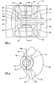
- the pump 10 is constituted by a piston 12 which is only drawn diagrammatically in figure 1 , and cylinder 14 which define between them, as the cylinder 14 moves relative to the piston 12, a pumping chamber 15a. Inlet and outlet ports of the cylinder 14 which are covered and uncovered by the piston 12 as the cylinder moves, and fluid flow paths to and from the pumping chamber 15. are not shown.
- the pumping chamber 15 is integrated with a linear drive motor which drives the cylinder 14 relative to the piston 12.
- the piston 12 is carried on a piston rod 13 which is fixed relative to a housing 18 of the pump 10 and thus is immovable.
- the cylinder 14 carries externally, a ring magnet 20.
- the cylinder 14 is provided externally, with a pair of locating formations 15, 16 which preferably each extend circumferentially about the cylinder 14.
- the locating formations 15, 16 may transmit a driving force between the ring magnet 20 and the cylinder 14.
- the ring magnet 20 may be located on the exterior of the cylinder 14 by one or more fasteners and/or by adhesive. In each case, as the magnet 20 is driven linearly along a cylinder axis A as described below, the cylinder 14 will be driven substantially linearly to and fro along the cylinder axis A.
- the suspension springs 22, 23 may each be provided by a group of one or more spiral springs, which provide high radial stiffness, but low resistance against tilt.
- the suspension springs 22, 23 are each mounted by a respective housing end wall 24, 25.
- the pump 10 further includes first and second cores 30, 31, which are provided side by side along the cylinder axis A.
- the first and second cores 30, 31 are of similar construction to each other, and the construction of the first core 30 which is seen in figure 2 will be described in detail.
- the first core 30 includes a segment of magnetic material, for example provided by a solid or laminated ferrous material, about which a first coil 32 is wound.
- the first core 30 provides a pair of yokes 34, 35, each of which presents a part cylindrical surface 34a, 35a which is centred on the cylinder axis A, the pair of yokes 34, 35 being diametrically opposite one another.
- Between the yokes 34, 35 is a first air gap 38 in which the cylinder 14 and ring magnet 20 sub-assembly is provided;
- the second core 31 is similar in construction to the first core 30 but at least that part of the second core 31 about which a second coil is wound, lies at an opposite side of a plane P which contains the cylindrical axis A, but the yokes of the second core 31 are positioned immediately adjacent the yokes 34, 35 of the first core 30, and provide between them a second air gap 39 aligned axially with the first air gap 38 and in which second air gap 39 the cylinder 14 and magnet 20 sub-assembly in use, also reciprocates.
- the first and second coils 32 are energised with an alternating or at least switched current.
- the ring magnet 20 and hence the cylinder 14 moves linearly to and fro along the cylinder axis A in the air gaps 38, 39, the instantaneous direction of cylinder 14 movement depending upon the direction of the current applied.
- the cylinder 14 and magnet 20 sub-assembly is an armature of a linear motor provided by the cores 30, 31, coils 32 and the sub-assembly.
- inlet and outlet ports (where provided) of the pumping chamber 15 are opened and closed thus to pump fluid.
- the electrical current applied to the coils 32 is alternating or switched at a frequency of for example between 50 and 75 Hertz, the suspension springs 14, 15 assisting arresting of cylinder 14 movement at each extreme of travel as the current direction reverses, and the commencing of movement in the opposite direction.
- the cylinder 14 carries externally a ring 45 of magnetic material which may include formations to locate the magnets, 40, 41 although if desired, instead of or in addition to such locating formations, the magnets 40, 41 may be located by one or more fasteners and/or adhesive.
- the magnetic material of the ring 45 joins the flux paths of the two magnets 40, 41 thus conducting the magnetic flux when the coils 32 are energised, between the yokes 34, 45 to the exterior of the cylinder 14 at least to reduce any magnetic damping effect on the movement of the cylinder 14 relative to the piston 12.
- this conduction of magnetic flux between the yokes 34, 35 is provided through the ring magnet 20.
- the yokes 34, 35 provided by the cores, and the windings of the coils 32 may be configured otherwise than as described, although preferably the coils 32 wound about the first and second cores 30, 31 are positioned at opposite sides of the plane P and the air gaps 38, 39 are adjacent one another along the cylindrical axis A.
- the pump housing 18 has end walls 24, 25 between which the cores 30, 31 are positioned. And the cylinder 14 linearly reciprocates in a space S provided between the end walls 24, 25, the pump housing 18 may be alternatively configured.
- the apparatus shown and described may be utilised for generating electrical energy, by relatively moving the piston 12 and cylinder 14, for example by introducing fluid, such as compressed air, into the chamber 15a between the piston 12 and cylinder 14, which in such an embodiment constitutes a driving chamber rather than a pumping chamber.
- the apparatus is an electromagnetic transducer either converting electrical energy to cylinder 14 movement, or cylinder 14 movement to electrical energy.
Landscapes
- Engineering & Computer Science (AREA)
- Mechanical Engineering (AREA)
- General Engineering & Computer Science (AREA)
- Power Engineering (AREA)
- Reciprocating, Oscillating Or Vibrating Motors (AREA)
- Compressors, Vaccum Pumps And Other Relevant Systems (AREA)
Claims (13)
- Un appareil transducteur électromagnétique comprenant un noyau (30, 31) comportant une paire d'étriers (34, 35) entre lesquels se trouve un intervalle d'air (38), au moins une bobine (32) disposée autour du noyau (30, 31), une armature déplaçable dans l'intervalle d'air (38, 39) lorsque la bobine (32) est alimentée, l'armature étant montée entre une paire de ressorts de suspension (22, 23), et caractérisée en ce que l'armature inclut un cylindre (14) dans lequel est disposé un piston (12) qui ne peut pas se déplacer par rapport au noyau (30, 31) et le cylindre (14) porte extérieurement un aimant annulaire (20) ou une paire d'aimants (40, 41), dans lequel, lorsqu'un aimant annulaire est présent, l'aimant annulaire est magnétisé de façon à ce que l'axe de magnétisation soit parallèle à la direction du flux magnétique dans l'intervalle d'air entre la paire d'étriers lorsque la bobine est alimentée, et dans lequel, lorsqu'une paire d'aimants est présente, les aimants sont chacun magnétisés dans la même direction parallèle à la direction du flux magnétique dans l'intervalle d'air entre la paire d'étriers.
- Un appareil selon la revendication 1, dans lequel le cylindre (14) de l'armature (20) et le piston (12) créent une chambre (15a) entre eux.
- Un appareil selon les revendications 1 ou 2, dans lequel, lorsque le cylindre (14) porte un aimant annulaire (20), l'aimant annulaire (20) est centré sur un axe de cylindre (A).
- Un appareil selon la revendication 3, dans lequel le cylindre (14) comporte une paire de formations circonférentielles externes (15, 16) entre lesquelles l'aimant annulaire (20) se trouve.
- Un appareil selon la revendication 4, dans lequel les formations de localisation (15, 16) transmettent, en cours d'utilisation, une force motrice entre l'aimant annulaire (20) et le cylindre (14).
- Un appareil selon n'importe laquelle des revendications précédentes, dans lequel le cylindre (14) porte un aimant annulaire (20) dans lequel les étriers (24, 35) présentent chacun à une surface externe cylindrique de l'aimant annulaire (20) une surface en partie cylindrique (34a, 35a) présentant une courbe correspondant à la courbe de l'aimant annulaire (20), faisant que les étriers (34, 35) sont continuellement proches de la surface externe cylindrique de l'aimant annulaire (20).
- Un appareil selon n'importe laquelle des revendications précédentes, dans lequel les aimants (40, 41) sont portés sur le bras (14) de façon à reposer à côté des étriers (34, 35).
- Un appareil selon n'importe laquelle des revendications précédentes, dans lequel le cylindre (14) porte extérieurement un anneau (45) de matériau magnétique qui rejoint les chemins de flux des deux aimants (40, 41), ce qui a pour effet de conduire le flux magnétique à l'extérieur du cylindre (14).
- Un appareil selon la revendication 8, dans lequel l'anneau (45) de matériau magnétique inclut des formations pour localiser les aimants (40, 41).
- Un appareil selon n'importe laquelle des revendications précédentes, dans lequel le noyau (30) fournit un premier chemin de flux et un deuxième chemin de flux est fourni par un deuxième noyau (31) de construction similaire au premier noyau (30) ayant une deuxième paire d'étriers (34, 35) créant un deuxième intervalle d'air (39) entre les deux, une deuxième bobine (32) étant présente autour du deuxième noyau (31).
- Un appareil selon la revendication 10, dans lequel le premier intervalle d'air (30) présent entre les étriers (34, 35) du premier noyau (30) et le deuxième intervalle d'air (39) sont positionnés l'un à côté de l'autre le long d'un axe de cylindre (A), et les première et deuxième bobines (32) sont positionnées sur des côtés opposés d'un plan longitudinal (P) dans lequel l'axe de cylindre (A) se trouve.
- Un pulsateur à pression ou une pompe comprenant un appareil transducteur électromagnétique selon n'importe laquelle des revendications précédentes.
- Un générateur électrique équipé d'un appareil transducteur électromagnétique selon n'importe laquelle des revendications 1 à 11.
Applications Claiming Priority (2)
| Application Number | Priority Date | Filing Date | Title |
|---|---|---|---|
| GB0606039A GB2436400B (en) | 2006-03-25 | 2006-03-25 | Electromagnetic Transducer Apparatus |
| PCT/GB2007/000875 WO2007110578A1 (fr) | 2006-03-25 | 2007-03-14 | transducteur électromagnétique |
Publications (2)
| Publication Number | Publication Date |
|---|---|
| EP2005564A1 EP2005564A1 (fr) | 2008-12-24 |
| EP2005564B1 true EP2005564B1 (fr) | 2012-10-17 |
Family
ID=36384205
Family Applications (1)
| Application Number | Title | Priority Date | Filing Date |
|---|---|---|---|
| EP07732017A Not-in-force EP2005564B1 (fr) | 2006-03-25 | 2007-03-14 | Transducteur électromagnétique |
Country Status (5)
| Country | Link |
|---|---|
| US (1) | US8049375B2 (fr) |
| EP (1) | EP2005564B1 (fr) |
| JP (1) | JP2009532011A (fr) |
| GB (1) | GB2436400B (fr) |
| WO (1) | WO2007110578A1 (fr) |
Families Citing this family (4)
| Publication number | Priority date | Publication date | Assignee | Title |
|---|---|---|---|---|
| DE102017122613B3 (de) * | 2017-09-28 | 2019-01-31 | Nidec Gpm Gmbh | Elektrischer Pumpenantrieb für eine Verdrängerpumpe, Verdrängerpumpe und Verfahren hierzu |
| DE102017122611B3 (de) * | 2017-09-28 | 2019-01-31 | Nidec Gpm Gmbh | Schwenkkolbenpumpe für Fluide |
| KR20250050951A (ko) * | 2022-08-18 | 2025-04-15 | 인슐렛 코포레이션 | 구동 코일이 있는 회전 솔레노이드 마이크로 액추에이터 |
| EP4715208A1 (fr) * | 2024-09-18 | 2026-03-25 | BSH Hausgeräte GmbH | Compresseur linéaire, système de refroidissement et appareil électroménager |
Citations (1)
| Publication number | Priority date | Publication date | Assignee | Title |
|---|---|---|---|---|
| US20060018771A1 (en) * | 2004-07-26 | 2006-01-26 | Lg Electronics Inc. | Reciprocating compressor |
Family Cites Families (16)
| Publication number | Priority date | Publication date | Assignee | Title |
|---|---|---|---|---|
| US2142094A (en) * | 1936-03-09 | 1939-01-03 | Bosch Gmbh Robert | Magneto |
| US3910729A (en) * | 1973-06-25 | 1975-10-07 | Air Prod & Chem | Compressor |
| JPH063190B2 (ja) * | 1985-09-25 | 1994-01-12 | 松下電工株式会社 | 電磁式ポンプ駆動装置 |
| US4674178A (en) * | 1985-10-16 | 1987-06-23 | Sundstrand Corporation | Method of fabricating a permanent magnet rotor |
| GB8909045D0 (en) * | 1989-04-21 | 1989-06-07 | Chancellor Masters | Compressors |
| US5012144A (en) * | 1989-06-27 | 1991-04-30 | Pneumo Abex Corporation | Linear direct drive motor |
| JP2773417B2 (ja) * | 1990-09-28 | 1998-07-09 | アイシン精機株式会社 | フリーピストンスターリングエンジン |
| US6404086B1 (en) * | 1996-09-13 | 2002-06-11 | Hitachi, Ltd. | Anisotropic magnet brushless motor having a rotor with elastic insulating support structure |
| CN1101615C (zh) * | 1997-10-04 | 2003-02-12 | 泽地公司 | 线性电机压缩机 |
| JPH11324914A (ja) * | 1998-05-19 | 1999-11-26 | Mitsubishi Electric Corp | リニア圧縮機 |
| JP3492228B2 (ja) * | 1999-02-09 | 2004-02-03 | 株式会社テクノ高槻 | 鉄心および該鉄心を用いる電磁駆動機構 |
| US6129527A (en) * | 1999-04-16 | 2000-10-10 | Litton Systems, Inc. | Electrically operated linear motor with integrated flexure spring and circuit for use in reciprocating compressor |
| JP2002339863A (ja) * | 2001-05-15 | 2002-11-27 | Showa Electric Wire & Cable Co Ltd | リニアコンプレッサ |
| CN100410281C (zh) | 2001-06-26 | 2008-08-13 | 巴塞尔聚烯烃意大利有限公司 | 烯烃聚合用组分和催化剂 |
| GB0122732D0 (en) * | 2001-09-20 | 2001-11-14 | Isis Innovations Ltd | Electromechanical transducer linear compressor and radio transmission antenna |
| CN1554868A (zh) * | 2003-12-23 | 2004-12-15 | 俞国淼 | 磁力直线活塞泵 |
-
2006
- 2006-03-25 GB GB0606039A patent/GB2436400B/en not_active Expired - Fee Related
-
2007
- 2007-03-14 US US12/294,449 patent/US8049375B2/en not_active Expired - Fee Related
- 2007-03-14 EP EP07732017A patent/EP2005564B1/fr not_active Not-in-force
- 2007-03-14 WO PCT/GB2007/000875 patent/WO2007110578A1/fr not_active Ceased
- 2007-03-14 JP JP2009502185A patent/JP2009532011A/ja active Pending
Patent Citations (1)
| Publication number | Priority date | Publication date | Assignee | Title |
|---|---|---|---|---|
| US20060018771A1 (en) * | 2004-07-26 | 2006-01-26 | Lg Electronics Inc. | Reciprocating compressor |
Also Published As
| Publication number | Publication date |
|---|---|
| US8049375B2 (en) | 2011-11-01 |
| GB2436400B (en) | 2011-11-30 |
| EP2005564A1 (fr) | 2008-12-24 |
| GB0606039D0 (en) | 2006-05-03 |
| WO2007110578A1 (fr) | 2007-10-04 |
| GB2436400A (en) | 2007-09-26 |
| US20100061867A1 (en) | 2010-03-11 |
| JP2009532011A (ja) | 2009-09-03 |
Similar Documents
| Publication | Publication Date | Title |
|---|---|---|
| US9800127B2 (en) | Reciprocating electric motor | |
| JP3927089B2 (ja) | リニアアクチュエータ、それを用いたポンプ装置並びにコンプレッサー装置 | |
| JP5433963B2 (ja) | リニアアクチュエータ | |
| JP3483959B2 (ja) | 磁石可動型リニアアクチュエータ及びポンプ | |
| US3931554A (en) | Reciprocating motor-compressor system | |
| US5231337A (en) | Vibratory acoustic compressor | |
| US10784734B2 (en) | Transverse flux reciprocating motor and reciprocating compressor including a transverse flux reciprocating motor | |
| CN102985692B (zh) | 线性压缩机 | |
| KR20060003092A (ko) | 왕복직선구동 액츄에이터 및 그를 이용한 전동칫솔 | |
| US5907201A (en) | Displacer assembly for Stirling cycle system | |
| US7247957B2 (en) | Electromechanical transducer linear compressor and radio transmission antenna | |
| JP5929241B2 (ja) | アクチュエーター及び電動理美容器具 | |
| US10876524B2 (en) | Linear compressor | |
| SA111320896B1 (ar) | محرك خطي توافقي بمغناطيس مغمور من دون نابض | |
| JP2001520499A (ja) | リニア運動を発生する電磁装置 | |
| EP2005564B1 (fr) | Transducteur électromagnétique | |
| CN102953956A (zh) | 一种无刷空心杯直线电机驱动的压缩机 | |
| CN101252305A (zh) | 振动式电动机 | |
| JP2004140901A (ja) | リニアモータおよびリニアコンプレッサ | |
| CN211830532U (zh) | 线性马达以及具有该线性马达的线性压缩机 | |
| EP2718567B1 (fr) | Compresseur à pistons libres avec transmission par torsion | |
| US20180198337A1 (en) | Moving core-type reciprocating motor and reciprocating compressor having the same | |
| JP2009213210A (ja) | 振動型モータ | |
| JP2002339863A (ja) | リニアコンプレッサ | |
| JP2005009397A (ja) | 振動型圧縮機 |
Legal Events
| Date | Code | Title | Description |
|---|---|---|---|
| PUAI | Public reference made under article 153(3) epc to a published international application that has entered the european phase |
Free format text: ORIGINAL CODE: 0009012 |
|
| 17P | Request for examination filed |
Effective date: 20081010 |
|
| AK | Designated contracting states |
Kind code of ref document: A1 Designated state(s): DE FR NL |
|
| DAX | Request for extension of the european patent (deleted) | ||
| RBV | Designated contracting states (corrected) |
Designated state(s): DE FR NL |
|
| 17Q | First examination report despatched |
Effective date: 20090617 |
|
| GRAP | Despatch of communication of intention to grant a patent |
Free format text: ORIGINAL CODE: EPIDOSNIGR1 |
|
| GRAS | Grant fee paid |
Free format text: ORIGINAL CODE: EPIDOSNIGR3 |
|
| GRAA | (expected) grant |
Free format text: ORIGINAL CODE: 0009210 |
|
| AK | Designated contracting states |
Kind code of ref document: B1 Designated state(s): DE FR NL |
|
| REG | Reference to a national code |
Ref country code: DE Ref legal event code: R096 Ref document number: 602007026137 Country of ref document: DE Effective date: 20121213 |
|
| REG | Reference to a national code |
Ref country code: NL Ref legal event code: T3 |
|
| PLBE | No opposition filed within time limit |
Free format text: ORIGINAL CODE: 0009261 |
|
| STAA | Information on the status of an ep patent application or granted ep patent |
Free format text: STATUS: NO OPPOSITION FILED WITHIN TIME LIMIT |
|
| 26N | No opposition filed |
Effective date: 20130718 |
|
| REG | Reference to a national code |
Ref country code: DE Ref legal event code: R097 Ref document number: 602007026137 Country of ref document: DE Effective date: 20130718 |
|
| PGFP | Annual fee paid to national office [announced via postgrant information from national office to epo] |
Ref country code: DE Payment date: 20140331 Year of fee payment: 8 |
|
| PGFP | Annual fee paid to national office [announced via postgrant information from national office to epo] |
Ref country code: FR Payment date: 20140225 Year of fee payment: 8 |
|
| PGFP | Annual fee paid to national office [announced via postgrant information from national office to epo] |
Ref country code: NL Payment date: 20140311 Year of fee payment: 8 |
|
| REG | Reference to a national code |
Ref country code: DE Ref legal event code: R119 Ref document number: 602007026137 Country of ref document: DE |
|
| REG | Reference to a national code |
Ref country code: NL Ref legal event code: MM Effective date: 20150401 |
|
| REG | Reference to a national code |
Ref country code: FR Ref legal event code: ST Effective date: 20151130 |
|
| PG25 | Lapsed in a contracting state [announced via postgrant information from national office to epo] |
Ref country code: DE Free format text: LAPSE BECAUSE OF NON-PAYMENT OF DUE FEES Effective date: 20151001 |
|
| PG25 | Lapsed in a contracting state [announced via postgrant information from national office to epo] |
Ref country code: FR Free format text: LAPSE BECAUSE OF NON-PAYMENT OF DUE FEES Effective date: 20150331 |
|
| PG25 | Lapsed in a contracting state [announced via postgrant information from national office to epo] |
Ref country code: NL Free format text: LAPSE BECAUSE OF NON-PAYMENT OF DUE FEES Effective date: 20150401 |