EP2005599B1 - Verbessertes verfahren zum decodieren digitaler daten in einem frequenzsprung-kommunikationssystem - Google Patents
Verbessertes verfahren zum decodieren digitaler daten in einem frequenzsprung-kommunikationssystem Download PDFInfo
- Publication number
- EP2005599B1 EP2005599B1 EP07752301.7A EP07752301A EP2005599B1 EP 2005599 B1 EP2005599 B1 EP 2005599B1 EP 07752301 A EP07752301 A EP 07752301A EP 2005599 B1 EP2005599 B1 EP 2005599B1
- Authority
- EP
- European Patent Office
- Prior art keywords
- bit
- frequency
- reliability
- data
- receiver
- Prior art date
- Legal status (The legal status is an assumption and is not a legal conclusion. Google has not performed a legal analysis and makes no representation as to the accuracy of the status listed.)
- Active
Links
Images


Classifications
-
- H—ELECTRICITY
- H04—ELECTRIC COMMUNICATION TECHNIQUE
- H04L—TRANSMISSION OF DIGITAL INFORMATION, e.g. TELEGRAPHIC COMMUNICATION
- H04L1/00—Arrangements for detecting or preventing errors in the information received
- H04L1/004—Arrangements for detecting or preventing errors in the information received by using forward error control
- H04L1/0045—Arrangements at the receiver end
- H04L1/0047—Decoding adapted to other signal detection operation
-
- H—ELECTRICITY
- H04—ELECTRIC COMMUNICATION TECHNIQUE
- H04B—TRANSMISSION
- H04B1/00—Details of transmission systems, not covered by a single one of groups H04B3/00 - H04B13/00; Details of transmission systems not characterised by the medium used for transmission
- H04B1/69—Spread spectrum techniques
- H04B1/713—Spread spectrum techniques using frequency hopping
-
- H—ELECTRICITY
- H04—ELECTRIC COMMUNICATION TECHNIQUE
- H04L—TRANSMISSION OF DIGITAL INFORMATION, e.g. TELEGRAPHIC COMMUNICATION
- H04L1/00—Arrangements for detecting or preventing errors in the information received
- H04L1/20—Arrangements for detecting or preventing errors in the information received using signal quality detector
- H04L1/205—Arrangements for detecting or preventing errors in the information received using signal quality detector jitter monitoring
-
- H—ELECTRICITY
- H04—ELECTRIC COMMUNICATION TECHNIQUE
- H04L—TRANSMISSION OF DIGITAL INFORMATION, e.g. TELEGRAPHIC COMMUNICATION
- H04L25/00—Baseband systems
- H04L25/02—Details ; arrangements for supplying electrical power along data transmission lines
- H04L25/06—DC level restoring means; Bias distortion correction ; Decision circuits providing symbol by symbol detection
- H04L25/069—DC level restoring means; Bias distortion correction ; Decision circuits providing symbol by symbol detection by detecting edges or zero crossings
-
- H—ELECTRICITY
- H04—ELECTRIC COMMUNICATION TECHNIQUE
- H04L—TRANSMISSION OF DIGITAL INFORMATION, e.g. TELEGRAPHIC COMMUNICATION
- H04L1/00—Arrangements for detecting or preventing errors in the information received
- H04L1/004—Arrangements for detecting or preventing errors in the information received by using forward error control
- H04L1/0056—Systems characterized by the type of code used
- H04L1/0071—Use of interleaving
Definitions
- the present disclosure relates generally to frequency hopping communication systems and, more particularly, to an improved method for decoding frequency hopped digital data using a forward error correcting scheme with erasure decoding capabilities.
- a modem In a frequency hopped waveform, it is possible to achieve modem acquisition in very high bit rate error conditions. In a jamming environment specifically, a modem can acquire with an on air bit error rate sometimes greater than 25-30%. However, it is important in this environment to provide a method of robust error correction in order to reliably decode a data stream at the receiver.
- Forward error correction is a method of controlling the received error rate of a user-provided data stream that is transmitted over a noisy channel.
- a forward error correction scheme will in general accomplish this by the generation and transmission of extra data along with the user data stream. This extra data provides the receiver with a more efficient way of determining what was actually transmitted across the channel.
- the performance of some forward error correcting schemes can be enhanced by indicating to the decoder which portions of a receive data stream are likely to be in error. The indicated portions are referred to as erasures.
- a forward error correction scheme that can make use of this information is referred to as having erasure decoding capabilities.
- Document GB 2 191 912 A discloses a data transmitting and/or decoding system utilizing frequency hopping provided with a Viterbi Decoder for performing "maximum likelihood decoding" in order to enable decoding of the signal to take place despite Doppler shifts. Further disclosed is a spectrum analyzer that analyses the frequency spectrum every hop and produces a measure of signal energy in each FFT resolution cell. The output of the spectrum analyzer is supplied to a decoder. The decoder examines all possible doppler paths, consistent with a doppler model, and chooses the most likely path through successive hops and symbols.
- Document WO 98/27681 A2 discloses a detector for use in a transmission system or recording system, using quality measures indicating the quality of the received signal, where the quality measure comprises the deviation of the position of transitions in the input signal from the nominal positions of said transitions. The quality measure is determined when a transition is present.
- the invention is defined by a method according to claim 1 and a receiver according to claim 7. Preferred embodiments are set out in the dependent claims.
- Frequency hopping is a method of transmitting radio signals by rapidly transmitting a carrier among many frequency channels. Briefly, a transmitter "hops" between available frequencies according to a specified algorithm. The transmitter operates in synchronization with a receiver, which remains tuned to the same frequency as the transmitter. A short burst of data is transmitted on a particular carrier frequency. The transmitter then tunes to another frequency and transmits again. Thus, the receiver is capable of hopping its frequency several times a second to follow the transmission frequency employed by the transmitter.
- Figure 1 depicts an improved method 10 for decoding digital data transmitted in a frequency hopping communication system.
- the communication system is assumed to employ a forward error correcting scheme with erasure capabilities. While the decoding methods of this disclosure are described in the context of a frequency hopping communication system, they may have application to other types of radio communication systems which transmit signals over multiple frequencies.
- the reliability of data bits received at a receiver is evaluated at 12 based on transition points between the data bits.
- a baseband sample stream must be sampled correctly with respect to its data bit transitions in order to have its modulated data correctly recovered.
- receiver's demodulator is aligned with the data bit transitions of the stream in a manner known in the art.
- transition points occur as sign changes and are commonly referred to as zero crossings.
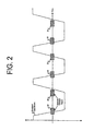
- an expected transition point can be derived for each data bit in the sampled stream. These data bit transitions are then monitored and assessed to determine whether they occur within an expected transition region as shown in Figure 2 . Data bits falling within the expected transition region as indicated at 22 have experienced considerably less noise than data bits falling out side of the expected transition region as indicated as 24. Thus, data bit transitions can provide an indication as to the reliability of the frequency over which the data bit was transmitted to the receiver.
- reliability metrics may be determined at 16 for each frequency over which data bits were received at the receiver.
- the reliability metric is derived from a comparison between the number of transition points which fall within the expected transition region and the total number of transition points seen.
- the reliability metric is defined as a ratio of the number of zero crossing that occur in the expected transition region to the total number of zero crossings that occur both inside and outside of the expected transition region.
- Other reliability metrics based on data bit transitions are also contemplated by this disclosure.
- the demodulator in a frequency hopped system knows the hopping sequence. Accordingly, the demodulator knows the frequency over which each data bit was transmitted to the receiver. For each hops' worth of data, a reliability ratio is computed from the data bits that were transmitted over the given frequency. Alternatively, the reliability ratio may be computed from data bits transmitted over a given frequency but sent over multiple hops.
- this ratio On a high signal to noise (i.e., low noise) frequency channel, this ratio will be close to unity. As the noise level increases, the ratio will also decease accordingly as more and more bit transitions occur outside the expected region. Thus, this ratio provides an indication as to the reliability of the frequency. In an exemplary embodiment, this ratio may be compared to an empirically derived threshold value. When the ratio for a given frequency greater than or equal to the threshold, the frequency is classified as reliable. When the ratio for the given frequency is lower than the threshold, the frequency is classified as unreliable. Alternatively, the ratio may be compared to multiple thresholds to determine different degrees of reliability. This reliability information is subsequently used when performing an decoding operation as indicated at 18. It is readily understood that the threshold may be set and adjusted based on system performance objectives.
- Figure 3 further illustrates how this decoding method may be integrated into a radio's receiver architecture.
- the radio receiver is generally comprised of a demodulator 32, a de-interleaver 36, and a decoder 38. While operation of these basic components is further described below, it is understood that other known radio receiver components may be needed for overall operation of the system.
- a received data signal is first input to the demodulator 32 which in turn demodulates the signal in a manner known in the art.
- the signal output from the demodulator 32 is commonly referred to as the baseband sample stream.
- the baseband sample stream is then input to a reliability metric generator 34.
- the reliability metric generator 34 is operable to determine reliability information for each frequency over which data bits were transmitted to the receiver. More specifically, the reliability metric generator 34 computes a reliability ratio for each frequency and compares the ratio to a threshold in the manner described above. This reliability information is then associated with each data bit in the baseband sample stream.
- a binary indicator bit is associated with each data bit. When a given frequency is deemed reliable, the reliability indicator is set to one; whereas, when the given frequency is deemed unreliable, the reliability indicator is set to zero.
- the reliability indicator may be comprised of two or more bits to represent different degrees of reliability information. This reliability indicator is commonly referred to as an erasure.
- the baseband sample stream may be comprised of the interleaved sequences IL1 + IL2 + IL3 + IL4 + IL5, where the each sequence was transmitted over a different frequency.
- the frequency assigned to the first interleaved sequence is deemed unreliable (i.e., 0.6 ⁇ 0.7).
- a reliability indicator bit of zero is associated with each bit in the sequence, such that the bit stream output by the reliability metric generator is as follows: (b 11 ,0), (b 21 ,0) (b 31 ,0), (b 41 ,0), (b 51 ,0).
- the frequency assigned to the second interleaved sequence is deemed reliable (i.e., 0.83 > 0.7).
- a reliability indicator bit of one is associated with each bit in the sequence as follows: (b 12 ,1), (b 22 ,1), (b 32 ,1), (b 42 ,1), (b 52 ,1).
- the data bits of the baseband sample stream are reformulated into bit pairs.
- the reformulated bit pairs are input to the de-interleaver 36.
- the de-interleaver 36 is adapted to account for the additional reliability bit associated with each incoming data bit, but otherwise operates in the manner known in the art to re-order the bit pairs into a sequence of codewords.
- the re-ordered bit pairs appear as: (b 11 ,0), (b 12 ,1), (b 13 ,1)
- the stream of re-ordered bit pairs is input into a decoder which employs a forward error correcting scheme with erasure capabilities.
- the decoder determines the number of bits having a value of one and the number of bits having a value of zero. Bits indicated as being transmitted over an unreliable frequency are ignored. If there are more ones than zeroes in a given codeword, the decoder outputs a value of one for the codeword. If there are more zeroes than ones in the codeword, the decoder outputs a value of zero for the codeword. For a tie, the decoder may make an arbitrary decision.
- the re-ordered bit pairs may be input to decoder which employ other decoding schemes (e.g., Reed-Solomon forward error correction scheme with erasure capabilities).
- decoding schemes e.g., Reed-Solomon forward error correction scheme with erasure capabilities.
Landscapes
- Engineering & Computer Science (AREA)
- Computer Networks & Wireless Communication (AREA)
- Signal Processing (AREA)
- Quality & Reliability (AREA)
- Power Engineering (AREA)
- Detection And Prevention Of Errors In Transmission (AREA)
- Error Detection And Correction (AREA)
- Digital Transmission Methods That Use Modulated Carrier Waves (AREA)
Claims (9)
- Verbessertes Verfahren (10) zum Decodieren von Daten in einem Frequenzsprungkommunikationssystem, das umfasst:- Überwachen von Übergangspunkten zwischen codierten Datenbits in einem Basisband-Datenstrom, wobei die Datenbits über verschiedene Übertragungsfrequenzen an einen Empfänger gesendet werden (12),- Bestimmen eines Zuverlässigkeitsindikators für jede Frequenz, über die Datenbits gesendet wurden (16), wobei der Zuverlässigkeitsindikator für eine gegebene Frequenz basierend auf den Übergangspunkten bezogen auf Datenbits bestimmt wird, die über die gegebene Frequenz gesendet wurden,- Zuordnen einer Zuverlässigkeitsmetrik zu jedem Datenbit in dem Basisband-Datenstrom, wobei die Zuverlässigkeitsmetrik für ein gegebenes Datenbit auf dem Zuverlässigkeitsindikator der Frequenz basiert, über die das Datenbit an den Empfänger gesendet wurde, und- Durchführen eines Decodiervorgangs unter Verwendung der jedem Datenbit zugewiesenen Zuverlässigkeitsmetrik.
- Verfahren nach Anspruch 1, das ferner das Demodulieren eines eingehenden Funksignals umfasst, um den Basisband-Datenstrom zu bilden.
- Verfahren nach Anspruch 1, wobei das Bestimmen einer Zuverlässigkeitsmetrik ferner das Bewerten von Übergangspunkten von Datenbits umfasst, die während eines einzelnen Sprungs auf einer gegebenen Frequenz gesendet wurden.
- Verfahren nach Anspruch 1, wobei das Bestimmen einer Zuverlässigkeitsmetrik ferner das Bewerten umfasst, ob die Bitübergänge innerhalb eines erwarteten Übergangsbereichs liegen, der von einer bekannten Bitrate des Datenstroms abgeleitet wird (24).
- Verfahren nach Anspruch 1, wobei das Bewerten der Bitübergänge ferner das Berechnen eines Verhältnisses zwischen einer Anzahl Bitübergänge, die innerhalb des erwarteten Übergangsbereichs liegen, und einer Gesamtzahl Bitübergänge umfasst, die sowohl innerhalb als auch außerhalb des erwarteten Übergangsbereichs liegen,- Klassifizieren einer gegebenen Frequenz, über die Datenbits empfangen wurden, als zuverlässig, wenn das Verhältnis für die gegebene Frequenz größer oder gleich einem vordefinierten Schwellenwert ist, und- Klassifizieren einer gegebenen Frequenz, über die Datenbits empfangen wurden, als unzuverlässig, wenn das Verhältnis für die gegebene Frequenz kleiner als der vordefinierte Schwellenwert ist.
- Verfahren nach Anspruch 5, wobei die Zuverlässigkeitsmetrik ferner als binärer Indikator definiert ist, der auf eins eingestellt wird, wenn die Frequenz als zuverlässig erachtet wird, und auf null eingestellt wird, wenn die Frequenz als unzuverlässig erachtet wird.
- Empfänger für ein Frequenzsprungkommunikationssystem, wobei Datenbits über verschiedene Übertragungsfrequenzen an den Empfänger gesendet werden, wobei der Empfänger umfasst:- einen Demodulator, der dafür ausgelegt ist, ein eingehendes codiertes Datensignal zu empfangen, und betriebsfähig dafür ausgelegt ist, das Datensignal zu demodulieren, um einen Basisband-Datenstrom zu bilden,- einen Zuverlässigkeitsmetrikgenerator, der dafür ausgelegt ist, den Basisband-Datenstrom vom Demodulator zu empfangen, und betriebsfähig dafür ausgelegt ist, für jede Frequenz, über die Datenbits im Basisband-Datenstrom empfangen wurden, einen Zuverlässigkeitsindikator zu berechnen, wobei der Zuverlässigkeitsmetrikgenerator ferner betriebsfähig dafür ausgelegt ist, den Zuverlässigkeitsindikator für eine gegebene Frequenz basierend auf Übergangspunkten von Datenbits zu berechnen, die über die gegebene Frequenz empfangen wurden,- wobei der Zuverlässigkeitsmetrikgenerator ferner betriebsfähig dafür ausgelegt ist, einen den Basisband-Datenstrom und eine zugeordnete Zuverlässigkeitsmetrik enthaltenden Bitstrom auszugeben, wobei die zugeordnete Zuverlässigkeitsmetrik auf dem Frequenzzuverlässigkeitsindikator basiert, der jedem Datenbit des Basisband-Datenstroms zugeordnet ist und auf der Frequenz basiert, über die das Datenbit an den Empfänger gesendet wurde, und- einen Decodierer, der dafür ausgelegt ist, den Bitstrom vom Zuverlässigkeitsmetrikgenerator zu empfangen, und betriebsfähig dafür ausgelegt ist, den Basisband-Datenstrom basierend zum Teil auf dem jedem Datenbit zugeordneten Zuverlässigkeitsindikator zu decodieren.
- Empfänger nach Anspruch 7, wobei der Zuverlässigkeitsmetrikgenerator den Zuverlässigkeitsindikator durch Bewerten, ob über eine gegebene Frequenz gesendete Bitübergänge innerhalb eines erwarteten Übergangsbereichs liegen, berechnet.
- Empfänger nach Anspruch 8, wobei der Zuverlässigkeitsmetrikgenerator ferner das Berechnen eines Verhältnisses zwischen einer Anzahl Bitübergänge, die innerhalb des erwarteten Übergangsbereichs liegen, und einer Gesamtzahl Bitübergänge, die sowohl innerhalb als auch außerhalb der erwarteten Übergangsbereiche liegen, und das Klassifizieren der gegebenen Frequenz als zuverlässig umfasst, wenn das Verhältnis für die gegebene Frequenz größer als ein vordefinierter Schwellenwert ist.
Applications Claiming Priority (2)
| Application Number | Priority Date | Filing Date | Title |
|---|---|---|---|
| US11/377,491 US7653117B2 (en) | 2006-03-16 | 2006-03-16 | Method for decoding digital data in a frequency hopping communication system |
| PCT/US2007/005587 WO2007108923A2 (en) | 2006-03-16 | 2007-03-06 | Improved method for decoding digital data in a frequency hopping communication system |
Publications (3)
| Publication Number | Publication Date |
|---|---|
| EP2005599A2 EP2005599A2 (de) | 2008-12-24 |
| EP2005599A4 EP2005599A4 (de) | 2012-07-18 |
| EP2005599B1 true EP2005599B1 (de) | 2013-09-11 |
Family
ID=38517781
Family Applications (1)
| Application Number | Title | Priority Date | Filing Date |
|---|---|---|---|
| EP07752301.7A Active EP2005599B1 (de) | 2006-03-16 | 2007-03-06 | Verbessertes verfahren zum decodieren digitaler daten in einem frequenzsprung-kommunikationssystem |
Country Status (4)
| Country | Link |
|---|---|
| US (2) | US7653117B2 (de) |
| EP (1) | EP2005599B1 (de) |
| CA (1) | CA2646187A1 (de) |
| WO (1) | WO2007108923A2 (de) |
Families Citing this family (6)
| Publication number | Priority date | Publication date | Assignee | Title |
|---|---|---|---|---|
| US8422395B2 (en) * | 2008-09-30 | 2013-04-16 | Microsoft Corporation | Resilient 1:N first-hop gateway selection mechanism |
| TWI411238B (zh) * | 2010-01-31 | 2013-10-01 | 晨星半導體股份有限公司 | 序列轉變位置的判斷方法及其裝置 |
| US8693897B2 (en) | 2011-01-22 | 2014-04-08 | Viasat, Inc. | Digital demodulator architecture |
| US8744279B2 (en) * | 2011-01-22 | 2014-06-03 | Viasat, Inc. | Adaptive PMD equalizer and implementation |
| US9583359B2 (en) | 2014-04-04 | 2017-02-28 | Fujifilm Planar Solutions, LLC | Polishing compositions and methods for selectively polishing silicon nitride over silicon oxide films |
| US11728843B2 (en) * | 2021-10-19 | 2023-08-15 | L3Harris Technologies, Inc. | Frequency hopping interference detection using decoder codeword metrics |
Family Cites Families (10)
| Publication number | Priority date | Publication date | Assignee | Title |
|---|---|---|---|---|
| GB2191912B (en) * | 1985-04-29 | 1988-12-14 | Signal Processors Ltd | Data transmission and decoding systems |
| US5430769A (en) * | 1992-11-23 | 1995-07-04 | Motorola, Inc. | Method and apparatus for controlling switched antenna diversity systems |
| US5452319A (en) | 1993-06-17 | 1995-09-19 | Itt Corporation | Method and system for increasing the reliability of multiple frequency communication systems |
| US6581179B1 (en) * | 1996-06-25 | 2003-06-17 | Ericsson Inc. | Methods for generating side information in the presence of time-selective fading |
| EP0885499B1 (de) * | 1996-12-18 | 2004-06-16 | Koninklijke Philips Electronics N.V. | Übertragungs- und aufzeichnungssystem mit vereinfachtem symboldetektor |
| US6240538B1 (en) * | 1998-09-10 | 2001-05-29 | Ericsson Inc. | Method and apparatus for errors and erasures decoding |
| US6584140B1 (en) * | 1999-01-22 | 2003-06-24 | Systems Information And Electronic Systems Integration Inc. | Spectrum efficient fast frequency-hopped modem with coherent demodulation |
| NZ520650A (en) | 2002-08-08 | 2005-08-26 | Tait Electronics Ltd | Improvements relating to radio communication systems |
| US7421006B2 (en) * | 2004-03-16 | 2008-09-02 | Harris Corporation | System and method for coherent multi-h continuous phase modulation waveform |
| US8476401B2 (en) * | 2004-09-10 | 2013-07-02 | Mitsubishi Rayon Co., Ltd. | Resist polymer, process for production thereof, resist composition, and process for production of substrated with patterns thereon |
-
2006
- 2006-03-16 US US11/377,491 patent/US7653117B2/en active Active
-
2007
- 2007-03-06 WO PCT/US2007/005587 patent/WO2007108923A2/en not_active Ceased
- 2007-03-06 EP EP07752301.7A patent/EP2005599B1/de active Active
- 2007-03-06 CA CA002646187A patent/CA2646187A1/en not_active Abandoned
-
2009
- 2009-08-27 US US12/548,574 patent/US8311075B2/en active Active
Also Published As
| Publication number | Publication date |
|---|---|
| EP2005599A2 (de) | 2008-12-24 |
| CA2646187A1 (en) | 2007-09-27 |
| US8311075B2 (en) | 2012-11-13 |
| WO2007108923A3 (en) | 2008-08-21 |
| EP2005599A4 (de) | 2012-07-18 |
| WO2007108923A2 (en) | 2007-09-27 |
| US7653117B2 (en) | 2010-01-26 |
| US20070217484A1 (en) | 2007-09-20 |
| US20090316754A1 (en) | 2009-12-24 |
Similar Documents
| Publication | Publication Date | Title |
|---|---|---|
| JP3850886B2 (ja) | 時間選択性フェージングが存在するときにサイド情報を発生する方法 | |
| US7817753B2 (en) | Reception quality estimating apparatus, wireless communication system, and reception quality estimating method | |
| JPH1093530A (ja) | 送信レート判定方法及び装置、並びにこれを用いた受信機 | |
| US8311075B2 (en) | Method for decoding digital data in a frequency hopping communication system | |
| US9973300B2 (en) | Modulation adaption method for multi-mode modems | |
| US5987631A (en) | Apparatus for measuring bit error ratio using a viterbi decoder | |
| EP0660978B1 (de) | Datendekoder und methode zur datendekodierung mit einer dynamisch indizierten kanalzustandsmetrik | |
| US20090055414A1 (en) | Method and system for feedback of decoded data characteristics to a decoder in stored data access and decoding operations to assist in additional decoding operations | |
| US9225469B2 (en) | Blind transport format detection depending on the conditions of reception of the signal | |
| US20020142728A1 (en) | Method for evaluating a radio link quality indicator in a wireless communication network and corresponding receiver | |
| US7890847B2 (en) | Apparatus and method for calculating error metrics in a digital communication system | |
| US9118480B2 (en) | Frame quality estimation during viterbi decoding | |
| JP5480589B2 (ja) | 通信装置、その中継方法及びプログラム | |
| US20070147548A1 (en) | Blind data rate identification for enhanced receivers | |
| CN101026430B (zh) | 一种去除干扰的方法及系统 | |
| JPH04219028A (ja) | 軟判定ビタビ復号方法 | |
| JP5120564B2 (ja) | 回線品質監視の方法およびその回路 | |
| Bei-Ming et al. | Complex position code parallel combinatory spread spectrum communication system with FEC technique | |
| EP1885079B1 (de) | Verfahren zur Qualitätsmessung eines Funkkanals und entsprechende Vorrichtung | |
| CN100471254C (zh) | 数字多媒体广播接收终端中的维特比解码器 | |
| Van Wyk et al. | Application of a burst-error-correction Viterbi algorithm to Q/sup 2/PSK on Rician fading channels | |
| Lu et al. | An investigation of coding for non-coherently demodulated binary FSK signals | |
| US20050141651A1 (en) | Method and system for modifying branch metric of Viterbi decoder for uncorrelated signals |
Legal Events
| Date | Code | Title | Description |
|---|---|---|---|
| PUAI | Public reference made under article 153(3) epc to a published international application that has entered the european phase |
Free format text: ORIGINAL CODE: 0009012 |
|
| 17P | Request for examination filed |
Effective date: 20081015 |
|
| AK | Designated contracting states |
Kind code of ref document: A2 Designated state(s): AT BE BG CH CY CZ DE DK EE ES FI FR GB GR HU IE IS IT LI LT LU LV MC MT NL PL PT RO SE SI SK TR |
|
| AX | Request for extension of the european patent |
Extension state: AL BA HR MK RS |
|
| RBV | Designated contracting states (corrected) |
Designated state(s): DE FR GB IT |
|
| A4 | Supplementary search report drawn up and despatched |
Effective date: 20120614 |
|
| RIC1 | Information provided on ipc code assigned before grant |
Ipc: H04B 1/00 20060101AFI20120608BHEP Ipc: H04B 1/713 20110101ALI20120608BHEP Ipc: H04L 25/06 20060101ALI20120608BHEP Ipc: H04L 1/20 20060101ALI20120608BHEP |
|
| DAX | Request for extension of the european patent (deleted) | ||
| GRAP | Despatch of communication of intention to grant a patent |
Free format text: ORIGINAL CODE: EPIDOSNIGR1 |
|
| RIC1 | Information provided on ipc code assigned before grant |
Ipc: H04L 25/06 20060101ALI20130301BHEP Ipc: H04B 1/00 20060101AFI20130301BHEP Ipc: H04L 1/20 20060101ALI20130301BHEP Ipc: H04B 1/713 20110101ALI20130301BHEP |
|
| INTG | Intention to grant announced |
Effective date: 20130402 |
|
| RIN1 | Information on inventor provided before grant (corrected) |
Inventor name: LEIBY, III, EDWIN, MCCALL Inventor name: VOGLEWEDE, PAUL Inventor name: SHAVER, JOSEPH Inventor name: CHAMBERLAIN, MARK, WALTER |
|
| GRAS | Grant fee paid |
Free format text: ORIGINAL CODE: EPIDOSNIGR3 |
|
| GRAA | (expected) grant |
Free format text: ORIGINAL CODE: 0009210 |
|
| AK | Designated contracting states |
Kind code of ref document: B1 Designated state(s): DE FR GB IT |
|
| REG | Reference to a national code |
Ref country code: GB Ref legal event code: FG4D |
|
| REG | Reference to a national code |
Ref country code: DE Ref legal event code: R096 Ref document number: 602007032802 Country of ref document: DE Effective date: 20131107 |
|
| REG | Reference to a national code |
Ref country code: DE Ref legal event code: R097 Ref document number: 602007032802 Country of ref document: DE |
|
| PLBE | No opposition filed within time limit |
Free format text: ORIGINAL CODE: 0009261 |
|
| STAA | Information on the status of an ep patent application or granted ep patent |
Free format text: STATUS: NO OPPOSITION FILED WITHIN TIME LIMIT |
|
| 26N | No opposition filed |
Effective date: 20140612 |
|
| REG | Reference to a national code |
Ref country code: DE Ref legal event code: R097 Ref document number: 602007032802 Country of ref document: DE Effective date: 20140612 |
|
| REG | Reference to a national code |
Ref country code: FR Ref legal event code: PLFP Year of fee payment: 10 |
|
| REG | Reference to a national code |
Ref country code: FR Ref legal event code: PLFP Year of fee payment: 11 |
|
| REG | Reference to a national code |
Ref country code: FR Ref legal event code: PLFP Year of fee payment: 12 |
|
| REG | Reference to a national code |
Ref country code: DE Ref legal event code: R082 Ref document number: 602007032802 Country of ref document: DE Representative=s name: WUESTHOFF & WUESTHOFF, PATENTANWAELTE PARTG MB, DE Ref country code: DE Ref legal event code: R081 Ref document number: 602007032802 Country of ref document: DE Owner name: HARRIS GLOBAL COMMUNICATIONS, INC., ALBANY, US Free format text: FORMER OWNER: HARRIS CORPORATION, MELBOURNE, FLA., US Ref country code: DE Ref legal event code: R081 Ref document number: 602007032802 Country of ref document: DE Owner name: HARRIS GLOBAL COMMUNICATIONS, INC., ALBANY, US Free format text: FORMER OWNER: HARRIS CORPORATION, MELBOURNE, FL, US |
|
| REG | Reference to a national code |
Ref country code: GB Ref legal event code: 732E Free format text: REGISTERED BETWEEN 20190207 AND 20190213 |
|
| P01 | Opt-out of the competence of the unified patent court (upc) registered |
Effective date: 20230530 |
|
| PGFP | Annual fee paid to national office [announced via postgrant information from national office to epo] |
Ref country code: GB Payment date: 20260327 Year of fee payment: 20 |
|
| PGFP | Annual fee paid to national office [announced via postgrant information from national office to epo] |
Ref country code: DE Payment date: 20260327 Year of fee payment: 20 |
|
| PGFP | Annual fee paid to national office [announced via postgrant information from national office to epo] |
Ref country code: IT Payment date: 20260319 Year of fee payment: 20 |
|
| PGFP | Annual fee paid to national office [announced via postgrant information from national office to epo] |
Ref country code: FR Payment date: 20260325 Year of fee payment: 20 |