EP2006043A1 - Tieflochbohrmaschine - Google Patents
Tieflochbohrmaschine Download PDFInfo
- Publication number
- EP2006043A1 EP2006043A1 EP07737762A EP07737762A EP2006043A1 EP 2006043 A1 EP2006043 A1 EP 2006043A1 EP 07737762 A EP07737762 A EP 07737762A EP 07737762 A EP07737762 A EP 07737762A EP 2006043 A1 EP2006043 A1 EP 2006043A1
- Authority
- EP
- European Patent Office
- Prior art keywords
- drilling
- coolant
- boring head
- deep
- boring
- Prior art date
- Legal status (The legal status is an assumption and is not a legal conclusion. Google has not performed a legal analysis and makes no representation as to the accuracy of the status listed.)
- Withdrawn
Links
Images


Classifications
-
- B—PERFORMING OPERATIONS; TRANSPORTING
- B23—MACHINE TOOLS; METAL-WORKING NOT OTHERWISE PROVIDED FOR
- B23B—TURNING; BORING
- B23B41/00—Boring or drilling machines or devices specially adapted for particular work; Accessories specially adapted therefor
- B23B41/02—Boring or drilling machines or devices specially adapted for particular work; Accessories specially adapted therefor for boring deep holes; Trepanning, e.g. of gun or rifle barrels
-
- B—PERFORMING OPERATIONS; TRANSPORTING
- B23—MACHINE TOOLS; METAL-WORKING NOT OTHERWISE PROVIDED FOR
- B23B—TURNING; BORING
- B23B51/00—Tools for drilling machines
-
- B—PERFORMING OPERATIONS; TRANSPORTING
- B23—MACHINE TOOLS; METAL-WORKING NOT OTHERWISE PROVIDED FOR
- B23B—TURNING; BORING
- B23B51/00—Tools for drilling machines
- B23B51/04—Drills for trepanning
- B23B51/0486—Drills for trepanning with lubricating or cooling equipment
-
- B—PERFORMING OPERATIONS; TRANSPORTING
- B23—MACHINE TOOLS; METAL-WORKING NOT OTHERWISE PROVIDED FOR
- B23B—TURNING; BORING
- B23B51/00—Tools for drilling machines
- B23B51/06—Drills with lubricating or cooling equipment
-
- E—FIXED CONSTRUCTIONS
- E21—EARTH OR ROCK DRILLING; MINING
- E21B—EARTH OR ROCK DRILLING; OBTAINING OIL, GAS, WATER, SOLUBLE OR MELTABLE MATERIALS OR A SLURRY OF MINERALS FROM WELLS
- E21B10/00—Drill bits
- E21B10/60—Drill bits characterised by conduits or nozzles for drilling fluids
- E21B10/602—Drill bits characterised by conduits or nozzles for drilling fluids the bit being a rotary drag type bit with blades
-
- B—PERFORMING OPERATIONS; TRANSPORTING
- B23—MACHINE TOOLS; METAL-WORKING NOT OTHERWISE PROVIDED FOR
- B23B—TURNING; BORING
- B23B2250/00—Compensating adverse effects during turning, boring or drilling
- B23B2250/12—Cooling and lubrication
-
- B—PERFORMING OPERATIONS; TRANSPORTING
- B23—MACHINE TOOLS; METAL-WORKING NOT OTHERWISE PROVIDED FOR
- B23B—TURNING; BORING
- B23B2251/00—Details of tools for drilling machines
- B23B2251/02—Connections between shanks and removable cutting heads
-
- B—PERFORMING OPERATIONS; TRANSPORTING
- B23—MACHINE TOOLS; METAL-WORKING NOT OTHERWISE PROVIDED FOR
- B23B—TURNING; BORING
- B23B2251/00—Details of tools for drilling machines
- B23B2251/56—Guiding pads
-
- B—PERFORMING OPERATIONS; TRANSPORTING
- B23—MACHINE TOOLS; METAL-WORKING NOT OTHERWISE PROVIDED FOR
- B23B—TURNING; BORING
- B23B2270/00—Details of turning, boring or drilling machines, processes or tools not otherwise provided for
- B23B2270/30—Chip guiding or removal
-
- B—PERFORMING OPERATIONS; TRANSPORTING
- B23—MACHINE TOOLS; METAL-WORKING NOT OTHERWISE PROVIDED FOR
- B23B—TURNING; BORING
- B23B51/00—Tools for drilling machines
- B23B51/06—Drills with lubricating or cooling equipment
- B23B51/063—Deep hole drills, e.g. ejector drills
-
- Y—GENERAL TAGGING OF NEW TECHNOLOGICAL DEVELOPMENTS; GENERAL TAGGING OF CROSS-SECTIONAL TECHNOLOGIES SPANNING OVER SEVERAL SECTIONS OF THE IPC; TECHNICAL SUBJECTS COVERED BY FORMER USPC CROSS-REFERENCE ART COLLECTIONS [XRACs] AND DIGESTS
- Y10—TECHNICAL SUBJECTS COVERED BY FORMER USPC
- Y10T—TECHNICAL SUBJECTS COVERED BY FORMER US CLASSIFICATION
- Y10T408/00—Cutting by use of rotating axially moving tool
- Y10T408/44—Cutting by use of rotating axially moving tool with means to apply transient, fluent medium to work or product
- Y10T408/45—Cutting by use of rotating axially moving tool with means to apply transient, fluent medium to work or product including Tool with duct
- Y10T408/455—Conducting channel extending to end of Tool
-
- Y—GENERAL TAGGING OF NEW TECHNOLOGICAL DEVELOPMENTS; GENERAL TAGGING OF CROSS-SECTIONAL TECHNOLOGIES SPANNING OVER SEVERAL SECTIONS OF THE IPC; TECHNICAL SUBJECTS COVERED BY FORMER USPC CROSS-REFERENCE ART COLLECTIONS [XRACs] AND DIGESTS
- Y10—TECHNICAL SUBJECTS COVERED BY FORMER USPC
- Y10T—TECHNICAL SUBJECTS COVERED BY FORMER US CLASSIFICATION
- Y10T408/00—Cutting by use of rotating axially moving tool
- Y10T408/89—Tool or Tool with support
- Y10T408/896—Having product-receiving chamber
Definitions
- the present invention relates to a deep-hole drilling machine for discharging cuttings (chips)generated during cutting outside thereof along with coolant supplied to the drilling portion by an external feeding system through the interior of a boring bar as in a so-called BTA (Boring Trepanning Association) system.
- BTA Biting Trepanning Association
- a hollow boring bar is employed, and at the same time, as shown in, for example, FIG. 4 , discharging openings 33a and 33b, which are open so as to face cutting blades 32a, 32c and 32b are provided at the tip end portion of a boring head 31 connected to the front end of a boring bar, wherein cuttings (chips) are discharged outside from the discharging openings 33a and 33b through the interior of the corresponding boring bar together with coolant supplied to the drilling portion.
- reference numeral 34 denotes a guide pad secured at the tip end side of the outer circumference of the boring head 31
- reference numeral 35 denotes a clamp groove secured slightly at the inner side of the outer circumference thereof.
- Coolant in the above-described inner supply system is introduced into a coolant supply path 40a between the inner tube 42 and the outer tube 43 at the proximal side of a double-tube type boring bar 41 as shown by the arrow in FIG. 5(A) , is flown outside through a coolant outlet 36 secured on the circumferential wall of the boring head 31 at the distal end side, and is supplied to the drilling portion side.
- the coolant is flown from the discharging openings 33a and 33b of the boring head 31 into a discharge passage 40b structured by the inner side of the inner tube 43 and is discharged outside along with cuttings (chips) generated in the drilling portion. Therefore, in this system, the flow resistance does not change at the supply side of coolant during cutting, wherein it does not matter to the discharge performance of cuttings (chips) that a cut hole H is made deep.
- coolant in the above-described outer supply system is supplied to the drilling portion through clearance T between the boring bar 41 and the inner circumference of a drilling hole H, and similarly, is discharged from the discharging openings 33a and 33b of the boring head 31 to the outside through the chip discharge passage 40 in the boring bar 41 along with the cuttings (chips) generated in the drilling portion.
- the supply path is lengthened, a pressure loss is accordingly increased due to the flow path resistance. Therefore, there is a shortcoming in this system that the deeper the drilling hole becomes, the worse the discharge performance of cuttings (chips) by means of coolant becomes.
- the present invention was developed in view of the above-described situations, and it is therefore an object of the present invention to provide a deep-hole drilling machine particularly as a machine for supplying coolant to the drilling portion by means of an outer supply system, which is capable of achieving high drilling efficiency, even if a drilling hole is deepened, by improving the distance performance of cuttings (chips) from the drilling portion without setting the supply pressure of coolant to a high level.
- the deep-hole drilling machine is configured so that a tubular boring head 2 having discharging openings 4a and 4b communicating with a chip discharge passage 10 is attached to cutting blades 3a and 3c at the distal end of a hollow boring bar 1 the interior of which is made into the chip discharge passage 10, coolant C is supplied from the exterior to the cutting blades 3a through 3c side through clearance between the outer circumferential surface of the boring bar 1 and the inner circumferential surface of a drilling hole H, and cuttings (chips) S generated by cutting are discharged from the discharging openings 4a and 4b to the outside through the chip discharge passage 10 along with the coolant C, and further includes bypass holes 5 diagonally provided at a plurality of points in the circumferential direction of the circumferential wall 21 of the boring head 2 so as to penetrate the circumferential wall 21 of the boring head 2 and so that the outer opening
- the deep-hole drilling machine according to a second aspect of the invention is a deep-hole drilling machine according to the first aspect, in which the respective bypass holes 5 described above are diagonally provided so that the outer opening 5a is positioned closer to the front side in the rotation direction of the corresponding boring head 2 than the inner opening 5b in relative rotation of the boring head 2 and a workpiece W.
- a part of coolant supplied from the outside to the drilling portion through clearance between the boring bar and the inner circumference of a drilling hole during cutting is caused to flow from the corresponding bypass holes in the interior of the boring head.
- the flow-in direction is diagonally provided toward the rear side, an induction force is generated toward the discharge side in the chip discharge passage, wherein cuttings (chips) are propelled to be discharged from the drilling portion by the induction force.
- the respective bypass holes described above are diagonally provided so that the outer opening is positioned further at the front side in the relative rotation direction of the boring head than the inner opening, a flow of the coolant through the respective bypass holes from the outside to the inside is propelled in line with relative rotation in cutting, and at the same time, eddies are brought about in the interior, wherein the induction force to the discharge side is further increased in the chip discharge passage, and higher drilling efficiency is further achieved since the discharge performance of cuttings (chips) is further increased.
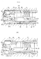
- FIG. 1 shows a boring head of the corresponding deep-hole drilling machine
- FIG. 2 shows the boring head side of the corresponding deep-hole drilling machine during cutting
- FIG. 3 shows a drilling state by the corresponding deep-hole drilling machine, respectively.
- the boring head 2 of the deep-hole drilling machine is roughly tubular, has its distal end formed to be acutely conical, and includes two large and small discharge holes 4a and 4b which are opened from the distal end face to the side and are fan-shaped when being observed from the distal end side.
- These discharging openings 4a and 4b communicate with the center bore 20 opened at its rear end, wherein a central cutting blade 3c and peripheral cutting blade 3a are attached to the edge face of the large discharging opening 4a, and an intermediate cutting blade 3b is fixed by welding to the edge face of the small discharging opening 4b.
- these cutting blades 3a through 3c are made of a cemented carbide alloy, and are disposed so that the blade tips are oriented roughly in the same diametrical direction.
- guide pads 6 and 6 are positioned and fixed near the distal end between both the discharging openings 4a and 4b at the outer circumference whose outer diameter is slightly larger, and at the same time, clamp grooves 7 and 7 are positioned and formed slightly inwardly of the outer circumference.
- a male threading portion 8 is provided on the outer circumference of the proximal portion 2c, and bypass holes 5 penetrating the inside and outside of the circumferential wall 21 are provided at a plurality of points (four points are illustrated) in the circumferential direction of the intermediate portion 2b.
- the outer opening 5a is positioned closer to the distal end side of the head than the inner opening 5b as shown in FIG. 2 (A) and (B) , and is diagonally provided so as to be positioned further at the front side in the relative rotation direction (the arrow direction Y shown in FIG. 2(A) ) when cutting using the corresponding boring head 2.
- a hollow boring bar of the deep-hole drilling machine is shaped to be like a round pipe as shown in FIG. 2(B) , and the interior thereof is constitutes a discharge passage 10. Since the male threading portion 8 at the proximal end 2c side of the boring head 2 is screwed in and tightened in female threading 11 secured on the inner circumference of the front end portion, the corresponding boring head 2 is concentrically linked with the distal end portion and held in a position. And, the linked boring head 2 is entered into a state where the distal end portion 2a is protruded from the distal end of the boring bar 1. However, annular clearance 9 is formed between the outer circumference of the intermediate portion 2b and the inner circumference of the distal end portion 12 of the boring bar 1, whereby the bypass holes 5 are caused to communicate with the exterior.
- the proximal end side of the boring bar 1 having a boring head 2 held at its distal end is linked to a spindle of a machine tool by means of a workpiece chuck (not illustrated), driven and rotated, or the workpiece W side is rotated.
- coolant is supplied from an outer supply system, wherein as shown in FIG.
- coolant C is supplied at a high pressure from the inlet port 15 into the corresponding jacket 13 in a state where the jacket 13 is pressed to a workpiece W via a seal link 14, the coolant C is supplied to the distal end side of the boring head 2 through clearance T between the outer circumferential surface of the boring bar 1 and the inner circumferential surface of a drilling hole H, and the coolant C is caused to flow from the discharging openings 4a and 4b of the boring head 2 into the chip discharge passage 10 in the boring bar 1 along with cuttings (chips) S generated at a drilling portion, and is then discharged outside.
- the outer opening 5a is diagonally provided so as to be positioned further at the front side in the rotation direction of the corresponding boring head 2 than the inner opening 5b as shown in FIG. 2(A) , flows of the coolant C passed through the bypass holes 5 from outside to inside are propelled in line with the relative rotations (in the arrow Y direction illustrated) of the boring bar 1 and the boring head 2, and further eddies are generated in the interior of the center bore 20, wherein the induction force to the discharge side is further increased.
- cuttings (chips) S generated in line with cutting are quickly moved from the discharging openings 4a and 4b into the center bore 20 along with the coolant C supplied to the drilling portion by an intensive induction force operating to the discharge side in the boring head 2, and are remarkably efficiently discharged through the chip discharge passage 10.
- such a mode is illustrated, which is composed of three cutting blades 3a through 3c, which are welded to and fixed at the boring head 2, and two discharging openings 4a and 4b.
- the present invention may be embodied in various modes, for example, a mode in which the boring head is composed of a single cutting blade and a single discharging opening, a mode in which the boring head is composed of five or more cutting blades of an odd number and two discharging openings, a mode in which the cutting blades are composed of a throw-away chip, or a mode in which cutting blades are integrally formed on the boring head.
- the boring head may be of an inner threading type contrary to the present embodiment and may be composed so that it is fitted to and screwed to the outside of the baring bar.
- the present invention may be subjected to various modifications and variations with respect to the detailed configuration regarding the number and formation position of bypass holes 5, number and attaching position of the guide pads, presence or absence and number of clamp grooves, etc.
Landscapes
- Engineering & Computer Science (AREA)
- Mechanical Engineering (AREA)
- Geology (AREA)
- Life Sciences & Earth Sciences (AREA)
- Mining & Mineral Resources (AREA)
- Environmental & Geological Engineering (AREA)
- Fluid Mechanics (AREA)
- Physics & Mathematics (AREA)
- General Life Sciences & Earth Sciences (AREA)
- Geochemistry & Mineralogy (AREA)
- Drilling Tools (AREA)
- Drilling And Boring (AREA)
- Earth Drilling (AREA)
Applications Claiming Priority (2)
| Application Number | Priority Date | Filing Date | Title |
|---|---|---|---|
| JP2006106089A JP4908900B2 (ja) | 2006-04-07 | 2006-04-07 | 深穴切削装置 |
| PCT/JP2007/054164 WO2007116620A1 (ja) | 2006-04-07 | 2007-03-05 | 深穴切削装置 |
Publications (2)
| Publication Number | Publication Date |
|---|---|
| EP2006043A1 true EP2006043A1 (de) | 2008-12-24 |
| EP2006043A4 EP2006043A4 (de) | 2011-01-19 |
Family
ID=38580922
Family Applications (1)
| Application Number | Title | Priority Date | Filing Date |
|---|---|---|---|
| EP07737762A Withdrawn EP2006043A4 (de) | 2006-04-07 | 2007-03-05 | Tieflochbohrmaschine |
Country Status (9)
| Country | Link |
|---|---|
| US (1) | US20090297285A1 (de) |
| EP (1) | EP2006043A4 (de) |
| JP (1) | JP4908900B2 (de) |
| KR (1) | KR20090003151A (de) |
| CN (1) | CN101360579B (de) |
| BR (1) | BRPI0706207A2 (de) |
| RU (1) | RU2401182C2 (de) |
| TW (1) | TW200800445A (de) |
| WO (1) | WO2007116620A1 (de) |
Cited By (4)
| Publication number | Priority date | Publication date | Assignee | Title |
|---|---|---|---|---|
| EP2202019A3 (de) * | 2008-12-25 | 2011-02-02 | Mori Seiki Co.,Ltd. | Werkzeug mit internem Flüssigkeitsdurchlauf |
| ITUD20100088A1 (it) * | 2010-04-29 | 2011-10-30 | Diafant S R L | Gruppo di lavorazione meccanica |
| RU183517U1 (ru) * | 2018-03-20 | 2018-09-25 | федеральное государственное бюджетное образовательное учреждение высшего образования "Донской государственный технический университет" (ДГТУ) | Фреза с комплексной системой охлаждения |
| US10975664B2 (en) | 2018-08-17 | 2021-04-13 | Ancor-Loc (Nz) Limited | Well or bore clearing tool |
Families Citing this family (23)
| Publication number | Priority date | Publication date | Assignee | Title |
|---|---|---|---|---|
| JP4895934B2 (ja) * | 2007-07-06 | 2012-03-14 | ユニタック株式会社 | ガンドリル |
| JP2010000581A (ja) * | 2008-06-23 | 2010-01-07 | Yunitakku Kk | 深孔切削用ドリルヘッド |
| JP5292045B2 (ja) * | 2008-10-03 | 2013-09-18 | ユニタック株式会社 | 深穴切削装置 |
| RU2481176C2 (ru) * | 2011-01-24 | 2013-05-10 | Константин Эдуардович Огоньков | Режущий инструмент (варианты) и способ резания |
| TWI422446B (zh) * | 2011-02-01 | 2014-01-11 | China Steel Corp | An annular deep hole processing apparatus and a method of machining the inner wall of the workpiece |
| RU2481925C2 (ru) * | 2011-02-21 | 2013-05-20 | Константин Эдуардович Огоньков | Крепежное устройство для режущих пластин |
| WO2014193785A1 (en) | 2013-05-28 | 2014-12-04 | Allied Machine & Engineering Corp. | Vacuum drilling system and methods |
| DE102013114792A1 (de) * | 2013-09-13 | 2015-03-19 | Jakob Lach Gmbh & Co. Kg | Zerspanungswerkzeug, insbesondere Bohr- und Fräswerkzeug |
| CN103909287B (zh) * | 2014-01-10 | 2017-03-08 | 宁波市荣科迈特数控刀具有限公司 | 组合式大孔深孔钻 |
| RU2563401C1 (ru) * | 2014-07-08 | 2015-09-20 | Федеральное государственное бюджетное образовательное учреждение высшего профессионального образования "Волгоградский государственный технический университет" (ВолгГТУ) | Способ механической обработки глубокого отверстия в трубной заготовке |
| AU2015215842B2 (en) * | 2014-08-20 | 2020-01-02 | TallyWalker Pty Ltd | Drill head |
| CN104786095B (zh) * | 2015-04-12 | 2017-02-01 | 娄底市洪申科技有限公司 | 一种高速切削刀具的散热装置及其散热方法 |
| WO2017053295A1 (en) * | 2015-09-22 | 2017-03-30 | Allied Machine & Engineering Corp. | Drilling system and methods for deep hole drilling |
| CN107914032A (zh) * | 2016-10-10 | 2018-04-17 | 中北大学 | 具有防偏功能的内排屑深孔钻 |
| CN106735456A (zh) * | 2016-11-11 | 2017-05-31 | 丹阳宝联五金制品有限公司 | 一种内排屑钻头 |
| WO2018112540A1 (en) * | 2016-12-23 | 2018-06-28 | TallyWalker Pty Ltd | Drill bit and drill head assembly |
| WO2019087656A1 (ja) * | 2017-10-30 | 2019-05-09 | 京セラ株式会社 | 切削工具及び切削加工物の製造方法 |
| CN110026591A (zh) * | 2019-04-22 | 2019-07-19 | 中北大学 | 一种深孔加工的智能高强度bta钻头 |
| CN112589149B (zh) * | 2020-10-30 | 2024-10-22 | 中北大学 | 一种内排屑深孔加工方法 |
| CN112453502B (zh) * | 2020-10-30 | 2024-11-08 | 中北大学 | 一种内排屑深孔钻 |
| JP7250257B1 (ja) | 2022-08-25 | 2023-04-03 | 株式会社タンガロイ | チップ及び切削工具 |
| CN117817014B (zh) * | 2024-03-05 | 2024-05-14 | 潍柴重机股份有限公司 | 喷吸钻及深直孔加工方法 |
| CN120244695B (zh) * | 2025-06-09 | 2025-08-12 | 江苏瑞骏达环保科技有限公司 | 一种风机主轴的镗孔设备及镗孔工艺 |
Family Cites Families (25)
| Publication number | Priority date | Publication date | Assignee | Title |
|---|---|---|---|---|
| GB1084269A (de) * | 1963-12-14 | 1900-01-01 | ||
| SE347450B (de) * | 1969-11-24 | 1972-08-07 | Sandvikens Jernverks Ab | |
| SU549272A2 (ru) * | 1975-12-29 | 1977-03-05 | Устройство дл глубокого сверлени | |
| GB1556661A (en) * | 1976-10-19 | 1979-11-28 | Gkn Transmissions Ltd | Drill heads and methods of drilling |
| JPS5727606A (en) * | 1980-07-25 | 1982-02-15 | Nippon Yakin:Kk | Deep hole cutting device |
| JPS5912405B2 (ja) * | 1980-07-25 | 1984-03-23 | 株式会社 日本冶金 | 深穴切削装置 |
| JPS57100417U (de) * | 1980-12-10 | 1982-06-21 | ||
| JPS57100417A (en) * | 1980-12-16 | 1982-06-22 | Victor Co Of Japan Ltd | Sigle-lens reflex type viewfinder |
| JPS59183715A (ja) * | 1983-04-01 | 1984-10-18 | 出川 義則 | 圧力釜を使用する炊飯方法およびライン装置 |
| JPS59183715U (ja) * | 1983-05-23 | 1984-12-07 | 三菱重工業株式会社 | 工具 |
| JPS60259303A (ja) * | 1985-06-03 | 1985-12-21 | Nippon Yakin:Kk | 深穴切削装置 |
| SU1282981A1 (ru) * | 1985-07-09 | 1987-01-15 | Одесский Политехнический Институт | Сверло |
| SU1342621A1 (ru) * | 1985-08-13 | 1987-10-07 | Специальное Конструкторское Бюро Алмазно-Расточных И Радиально-Сверлильных Станков | Станок дл обработки отверстий в детал х эжекторными сверлами |
| SU1315167A1 (ru) * | 1986-03-26 | 1987-06-07 | Предприятие П/Я А-7179 | Способ подачи смазочно-охлаждающей среды в зону резани |
| SU1472187A1 (ru) * | 1986-07-09 | 1989-04-15 | Предприятие П/Я А-7179 | Инструмент дл обработки отверстий |
| JPS6353611U (de) * | 1986-09-26 | 1988-04-11 | ||
| SU1572765A1 (ru) * | 1988-03-09 | 1990-06-23 | Одесский Политехнический Институт | Инструмент дл обработки отверстий |
| SU1673307A1 (ru) * | 1989-01-25 | 1991-08-30 | Ленинградский Механический Институт Маршала Советского Союза Устинова Д.Ф. | Устройство дл эжекторного сверлени глубоких отверстий |
| JPH02114413U (de) * | 1989-02-28 | 1990-09-13 | ||
| JPH0790408B2 (ja) * | 1989-03-10 | 1995-10-04 | 日立精機株式会社 | 深穴加工用工具 |
| DE4204428C2 (de) * | 1992-02-14 | 1994-02-03 | Dornier Luftfahrt | Hohlbohrwerkzeug zur Herstellung von zylindrischen Bohrungen |
| SE509383C2 (sv) * | 1994-06-13 | 1999-01-18 | Sandvik Ab | Borrverktyg |
| JP4057863B2 (ja) * | 2002-08-29 | 2008-03-05 | ユニタック株式会社 | 深穴切削装置 |
| SE526387C2 (sv) * | 2003-05-08 | 2005-09-06 | Seco Tools Ab | Borr för spånavskiljande bearbetning med alla delar utförda i ett material samt med innesluten spolkanal |
| CN2626654Y (zh) * | 2003-06-20 | 2004-07-21 | 顺德市顺达电脑厂有限公司 | 钻头 |
-
2006
- 2006-04-07 JP JP2006106089A patent/JP4908900B2/ja not_active Expired - Lifetime
-
2007
- 2007-03-05 EP EP07737762A patent/EP2006043A4/de not_active Withdrawn
- 2007-03-05 KR KR1020087014154A patent/KR20090003151A/ko not_active Ceased
- 2007-03-05 RU RU2008130675/02A patent/RU2401182C2/ru not_active IP Right Cessation
- 2007-03-05 US US12/094,442 patent/US20090297285A1/en not_active Abandoned
- 2007-03-05 CN CN2007800014962A patent/CN101360579B/zh active Active
- 2007-03-05 BR BRPI0706207-9A patent/BRPI0706207A2/pt not_active IP Right Cessation
- 2007-03-05 WO PCT/JP2007/054164 patent/WO2007116620A1/ja not_active Ceased
- 2007-04-04 TW TW096111951A patent/TW200800445A/zh not_active IP Right Cessation
Cited By (5)
| Publication number | Priority date | Publication date | Assignee | Title |
|---|---|---|---|---|
| EP2202019A3 (de) * | 2008-12-25 | 2011-02-02 | Mori Seiki Co.,Ltd. | Werkzeug mit internem Flüssigkeitsdurchlauf |
| US8622661B2 (en) | 2008-12-25 | 2014-01-07 | Mori Seiki Co., Ltd. | Tool with internal fluid passage |
| ITUD20100088A1 (it) * | 2010-04-29 | 2011-10-30 | Diafant S R L | Gruppo di lavorazione meccanica |
| RU183517U1 (ru) * | 2018-03-20 | 2018-09-25 | федеральное государственное бюджетное образовательное учреждение высшего образования "Донской государственный технический университет" (ДГТУ) | Фреза с комплексной системой охлаждения |
| US10975664B2 (en) | 2018-08-17 | 2021-04-13 | Ancor-Loc (Nz) Limited | Well or bore clearing tool |
Also Published As
| Publication number | Publication date |
|---|---|
| US20090297285A1 (en) | 2009-12-03 |
| WO2007116620A1 (ja) | 2007-10-18 |
| CN101360579B (zh) | 2010-11-10 |
| BRPI0706207A2 (pt) | 2011-03-15 |
| RU2008130675A (ru) | 2010-01-27 |
| RU2401182C2 (ru) | 2010-10-10 |
| CN101360579A (zh) | 2009-02-04 |
| TWI320005B (de) | 2010-02-01 |
| TW200800445A (en) | 2008-01-01 |
| KR20090003151A (ko) | 2009-01-09 |
| JP2007276056A (ja) | 2007-10-25 |
| JP4908900B2 (ja) | 2012-04-04 |
| EP2006043A4 (de) | 2011-01-19 |
Similar Documents
| Publication | Publication Date | Title |
|---|---|---|
| US20090297285A1 (en) | Deep hole drilling machine | |
| EP1419839B1 (de) | Tiefbohrwerkzeug | |
| US20110280675A1 (en) | Method for Forming Through-Hole | |
| JP5292045B2 (ja) | 深穴切削装置 | |
| US20180272442A1 (en) | Modular rotary tool and modular tool system | |
| EP2216115A1 (de) | Kanonenbohrer | |
| CN104968882B (zh) | 挖掘工具 | |
| JP2002321111A (ja) | 深穴切削装置 | |
| KR20090085567A (ko) | 드릴 헤드의 제조 방법 | |
| WO2006132068A1 (ja) | 深孔加工用ドリルヘッド | |
| US20110067927A1 (en) | Drill Head for Deep-Hole Drilling | |
| CN112974921B (zh) | 钻孔工具 | |
| KR20170135513A (ko) | 내부 경로를 통한 절삭유 공급 구조의 공작 공구 | |
| US20250332642A1 (en) | Cutting tool for use in hole machining and tool body of such cutting tool | |
| JP5072497B2 (ja) | 切削工具およびそれを用いた切削方法 | |
| JP4644552B2 (ja) | 深穴切削装置 | |
| US20110079445A1 (en) | Drill Head for Deep-Hole Drilling | |
| JP2004283969A (ja) | 深孔切削具 | |
| KR101946199B1 (ko) | 내부 경로를 통한 절삭유 공급 구조의 공작 공구 | |
| JP2004283970A (ja) | 深孔切削具 | |
| JP2005034976A (ja) | 切削工具 | |
| JP2004160625A (ja) | 深穴切削具 | |
| JP2005262330A (ja) | スローアウェイ式ドリル | |
| JP2003175413A (ja) | ドリル |
Legal Events
| Date | Code | Title | Description |
|---|---|---|---|
| PUAI | Public reference made under article 153(3) epc to a published international application that has entered the european phase |
Free format text: ORIGINAL CODE: 0009012 |
|
| 17P | Request for examination filed |
Effective date: 20080528 |
|
| AK | Designated contracting states |
Kind code of ref document: A1 Designated state(s): AT BE BG CH CY CZ DE DK EE ES FI FR GB GR HU IE IS IT LI LT LU LV MC MT NL PL PT RO SE SI SK TR |
|
| A4 | Supplementary search report drawn up and despatched |
Effective date: 20101220 |
|
| RIC1 | Information provided on ipc code assigned before grant |
Ipc: B23B 51/06 20060101AFI20071213BHEP Ipc: B23B 51/04 20060101ALI20101214BHEP |
|
| STAA | Information on the status of an ep patent application or granted ep patent |
Free format text: STATUS: THE APPLICATION HAS BEEN WITHDRAWN |
|
| 18W | Application withdrawn |
Effective date: 20120629 |
|
| DAX | Request for extension of the european patent (deleted) |