EP2006097A2 - Unités de support pour un cylindre d'impression d'une machine d'impression - Google Patents
Unités de support pour un cylindre d'impression d'une machine d'impression Download PDFInfo
- Publication number
- EP2006097A2 EP2006097A2 EP08152503A EP08152503A EP2006097A2 EP 2006097 A2 EP2006097 A2 EP 2006097A2 EP 08152503 A EP08152503 A EP 08152503A EP 08152503 A EP08152503 A EP 08152503A EP 2006097 A2 EP2006097 A2 EP 2006097A2
- Authority
- EP
- European Patent Office
- Prior art keywords
- bearing
- bearing unit
- unit according
- housing
- outer ring
- Prior art date
- Legal status (The legal status is an assumption and is not a legal conclusion. Google has not performed a legal analysis and makes no representation as to the accuracy of the status listed.)
- Granted
Links
- 238000007639 printing Methods 0.000 title claims abstract description 57
- 238000003860 storage Methods 0.000 claims description 19
- 230000002093 peripheral effect Effects 0.000 claims description 12
- 238000005096 rolling process Methods 0.000 claims description 7
- 230000005540 biological transmission Effects 0.000 claims description 2
- 238000000034 method Methods 0.000 abstract description 15
- 238000005452 bending Methods 0.000 abstract description 8
- 230000005284 excitation Effects 0.000 description 4
- 238000004519 manufacturing process Methods 0.000 description 4
- 230000009471 action Effects 0.000 description 3
- 238000013016 damping Methods 0.000 description 3
- 238000006073 displacement reaction Methods 0.000 description 3
- 230000010354 integration Effects 0.000 description 3
- 230000009467 reduction Effects 0.000 description 3
- 230000001133 acceleration Effects 0.000 description 2
- 230000008859 change Effects 0.000 description 2
- 230000008878 coupling Effects 0.000 description 2
- 238000010168 coupling process Methods 0.000 description 2
- 238000005859 coupling reaction Methods 0.000 description 2
- 230000006378 damage Effects 0.000 description 2
- 230000005484 gravity Effects 0.000 description 2
- 230000028161 membrane depolarization Effects 0.000 description 2
- 238000007645 offset printing Methods 0.000 description 2
- 230000003068 static effect Effects 0.000 description 2
- 230000003044 adaptive effect Effects 0.000 description 1
- 239000000853 adhesive Substances 0.000 description 1
- 230000001070 adhesive effect Effects 0.000 description 1
- 230000000712 assembly Effects 0.000 description 1
- 238000000429 assembly Methods 0.000 description 1
- 230000033228 biological regulation Effects 0.000 description 1
- 238000006243 chemical reaction Methods 0.000 description 1
- 238000010276 construction Methods 0.000 description 1
- 230000007547 defect Effects 0.000 description 1
- 230000001066 destructive effect Effects 0.000 description 1
- 238000001514 detection method Methods 0.000 description 1
- 230000008030 elimination Effects 0.000 description 1
- 238000003379 elimination reaction Methods 0.000 description 1
- 238000005516 engineering process Methods 0.000 description 1
- 239000003822 epoxy resin Substances 0.000 description 1
- 230000002349 favourable effect Effects 0.000 description 1
- 238000009434 installation Methods 0.000 description 1
- 239000002655 kraft paper Substances 0.000 description 1
- 235000015095 lager Nutrition 0.000 description 1
- 230000007246 mechanism Effects 0.000 description 1
- 230000010355 oscillation Effects 0.000 description 1
- 239000000123 paper Substances 0.000 description 1
- 230000000737 periodic effect Effects 0.000 description 1
- 229920000647 polyepoxide Polymers 0.000 description 1
- 230000036316 preload Effects 0.000 description 1
- 238000003825 pressing Methods 0.000 description 1
- 230000008569 process Effects 0.000 description 1
- 125000006850 spacer group Chemical group 0.000 description 1
- 229920003002 synthetic resin Polymers 0.000 description 1
- 239000000057 synthetic resin Substances 0.000 description 1
- 230000003313 weakening effect Effects 0.000 description 1
Images


Classifications
-
- B—PERFORMING OPERATIONS; TRANSPORTING
- B41—PRINTING; LINING MACHINES; TYPEWRITERS; STAMPS
- B41F—PRINTING MACHINES OR PRESSES
- B41F13/00—Common details of rotary presses or machines
- B41F13/08—Cylinders
- B41F13/24—Cylinder-tripping devices; Cylinder-impression adjustments
- B41F13/26—Arrangement of cylinder bearings
-
- B—PERFORMING OPERATIONS; TRANSPORTING
- B41—PRINTING; LINING MACHINES; TYPEWRITERS; STAMPS
- B41F—PRINTING MACHINES OR PRESSES
- B41F13/00—Common details of rotary presses or machines
- B41F13/08—Cylinders
- B41F13/24—Cylinder-tripping devices; Cylinder-impression adjustments
-
- B—PERFORMING OPERATIONS; TRANSPORTING
- B41—PRINTING; LINING MACHINES; TYPEWRITERS; STAMPS
- B41F—PRINTING MACHINES OR PRESSES
- B41F13/00—Common details of rotary presses or machines
- B41F13/08—Cylinders
- B41F13/24—Cylinder-tripping devices; Cylinder-impression adjustments
- B41F13/26—Arrangement of cylinder bearings
- B41F13/30—Bearings mounted on sliding supports
Definitions
- the invention relates to storage units for a printing cylinder of a printing press according to the preamble of claim 1 or 2.
- the active vibration damping techniques described above are almost exclusively used for damping resonantly forced vibrations in machine tools where there is continuous excitation (imbalance, chatter marks, process forces). In this case, low, continuously introduced forces are sufficient for damping, which are derived from a metrological detection of the actual value and a control algorithm.
- the channel impact vibrations of printing cylinders are caused by a single per revolution or periodic, pulse-shaped excitation.
- the force is applied by eliminating or reducing the pressing force when the interruption of the lateral surface is overrun (eg clamping channel of the opening for receiving an elevator). Due to the very short-term impact stimulus and the requirement to almost completely suppress the first vibration, which would otherwise already be visible as a quality defect in the printed product, new concepts regarding actuator technology and control are required.
- a bearing assembly for a printing machine wherein between a bearing inner ring and a bearing outer ring rolling elements are arranged and the bearing outer ring has a lateral mounting flange, with which it can be fixed to a housing.
- At least one piezoelectric adjusting element is arranged between the housing and the bearing outer ring, via which an exact radial positioning of the bearing lying in the micrometer range can be achieved in the housing bore, before the bearing is then fixed in the usual manner by means of screws on the housing. In the printing operation of the printing press, the bearing is thus rigidly fixed relative to the housing.
- the invention has for its object to provide storage units for a printing cylinder of a printing press.
- a force can be introduced which compensates for the elimination or reduction of the compressive stress when rolling over a cylinder channel, for example a clamping channel of a plate cylinder, and thus avoids vibration excitation.
- radial forces are introduced by means of the piezo actuators via the bearing in the printing cylinder, which substantially correspond in size and duration of action of the channel impact force. If the sum of the channel impact force and the actuator force is equal to zero at any time, movement of the center of gravity of the cylinder can be avoided.
- the invention enables integration of a suitable actuator for moving the bearing center of the printing cylinder and a suitable measuring system for calculating the Aktorstellkurve in a pre-assembled, compact storage unit that meets the requirements for space and connecting structures of a printing cylinder in a printing press.
- the compact and easy-to-install bearing unit which is pre-assembled, adjusted, eg B. mounted by shrink fit on the shaft seat of the printing cylinder and is mounted completely with the printing cylinder to a side frame of the printing press, resulting in no collision with adjacent modules such as page register or drive;
- the actuators and the power electronics are mounted on the bearing housing, ie on fixed components.
- Actuator dimensions are required in the currently typical printing unit loads, which can be rounded off in the preferred cross-sectional shape of the bearing unit, that is to say the preload side is rounded and the actuator sides are square.
- the effective actuator length can thus be increased to approximately 50% of the cylinder radius. After the stroke is proportional to the effective length of piezo actuators Actuators relevant size can be installed, while still sufficient space for radial bearings is guaranteed.
- an integration of actuators and sensors in a compact unit in the form of a storage unit is thus possible, with maximum utilization of the available installation space.
- a plate cylinder for example, a web-fed rotary printing press, such as a web-fed rotary offset printing machine
- the space constraint in the radial direction essentially results from the requirement to be able to apply several inking or dampening rollers with corresponding adjustment mechanisms around the outer surface of the plate cylinder and between plate cylinder and blanket cylinder the required center distance observed.
- the bearing unit may comprise a side register adjustment device, which may include a thrust bearing for axially adjusting the recorded in the storage unit printing cylinder, which may be adjustable by means of a threaded device.
- a side register adjustment device which may include a thrust bearing for axially adjusting the recorded in the storage unit printing cylinder, which may be adjustable by means of a threaded device.
- a storage unit is particularly suitable for use in connection with plate cylinders.
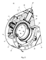
- the bearing unit 01 is used to hold a cylinder 02 not shown here (see. Fig. 4 ), in particular printing cylinder 02, for example, forme cylinder 02 or blanket cylinder 02 of a printing press, in particular a web-fed rotary printing press, for example a web-fed rotary offset printing press.
- the printing unit cylinder 02 mounted in the bearing unit 01 can in particular be a printing cylinder 02 with a single cylinder channel on the circumference.
- the storage unit 01 can be fastened, for example, on a side frame of the printing press, z. B. screwed, it being understood that on both sides of the cylinder 02 each have a bearing unit 01 is provided.
- the bearing unit 01 comprises a bearing 03, for example, a roller bearing 03, with an axial bore 04 for receiving a pin 06 (see. Fig. 4 )
- the bearing 03 includes a bearing inner ring 08, which defines the bore 04, a bearing outer ring 09 which is rotatably received in the bearing housing 07, and a recorded between bearing inner ring 08 and bearing outer ring 09 Wälzoasasatz 10.
- the bearing housing 07 is firmly screwed through threaded holes 11 with a side frame of the printing press, not shown.
- the bearing outer ring 09 is received in the bore 14 of the bearing housing 07 with radial play.
- the bearing outer ring 09 has on both sides a radially outwardly extending flange 12 and a contact shoulder 12, which extends into a correspondingly shaped, adjoining the bore 14 recess 13 on the respective end outer side of the bearing housing 07.
- the bearing outer ring 09 in the bearing housing 07 in the radial direction, d. H. in a plane perpendicular to the bearing axis movable, but received immovably in the axial direction due to the double-acting axial sliding of the abutment shoulders 12.
- the radially outwardly extending abutment shoulders 12 additionally cause a stiffening of the bearing outer ring 09, which is advantageous in view of the bending stress of the bearing outer ring 09 by the actuators 26 described below.
- the bearing housing 07 is formed divisible and comprises two housing halves 16; 17, which are joined together by means of dowel pins 18 and are screwed together.
- the dividing plane of the two housing halves 16; Preferably, the bearing outer ring 09 is divided Peripheral portion 17 of the other housing half 17 is rectangular.
- the length L1 of the long side of the rectangular housing half 17 may in particular correspond to twice the radius R of the semicircular or semicircular housing half 16 and the length L2 of the short side of the rectangular housing half may in particular correspond to the simple radius R.
- the bearing 03 or the bearing outer ring 09 is mounted as explained above with play in the bore 14 of the bearing housing 07.
- a rotation 19 in the form of a torsionally stiff, but flexible securing plate 19 is provided, which is annular with a ring-like portion 21 and a plurality, in particular four radially outwardly extending cranked arms 22, which preferably extend from each other at an angle of 90 °, and are preferably oriented so that two of the arms 22 extend in the direction of the two corners of the rectangular housing half 17.
- the annular portion 21 of the locking plate 19 is secured by screws 23 on the bearing outer ring 09, while the cranked arms 22 are fixed by screws 24 on the bearing housing 07, whereby a rotation 19 of the bearing outer ring 09 is created with simultaneous possibility of movement in the radial direction.
- each actuator 26 In the rectangular housing half 17 of the bearing housing 07 are two piezoelectric actuators 26, z. As actuators 26, for example, two piezo stack actuators 26 with integrated force plate arranged. The actuators 26 are completely received within the bearing housing 07. The actuators 26 extend The plane of each actuator 26 preferably extends perpendicular to the axis of the bearing 03 or the axis of the bearing 03 is preferably in the defined by the respective actuator 26 Level.
- the two actuators 26 are arranged at an angle of 90 ° + f 10% to each other, preferably 90 ° +/- 3%, in particular of 90 ° to each other, so in each case each have a vertical direction of action.
- the actuators 26 act with their radially inner end on the bearing outer ring 09 in the sense of moving the bearing outer ring 09 and thus the entire bearing 03 in a radial plane and are supported at its radially outer end on the bearing housing 07.
- a linear guide 29, z. B. a flat cage guide 29, in particular a needle rollers or balls having needle roller flat cage 29 may be provided.
- the two outer corner portions 27 of the rectangular housing half 17 are formed as detachable from the bearing housing 07 caps 27, in which the rear ends of the actuators 26 are encapsulated and supported by synthetic resin.
- the caps 27 in turn are fastened by means of screws 28 to the rectangular housing half 17.
- the actuators 26 via the actuators 26, the forces are directly over the stiffened by the flanges 12 bearing outer ring 09 in the center plane (therefore no torque input by Aktorkraft ) of the rigid bearing point initiated (the central axis of the actuator 27 is within the Wälz Scientificbachn and / or the working width of the rolling bearing 03); the actuators 26 are based on the bearing housing 07 directly from the rigid side frame of the printing press; to compensate for length or angle tolerances, the actuators 26 on the front side in each case an intermediate element 29 for transverse force coupling to the z. B. needle rollers having flat cage guide 29 is pressed and the back is set on each a spacer between the cap 27 and the bearing housing 07, an adhesive gap, which is poured with epoxy resin.
- the two actuators 26 opposite, preferably diametrically opposite each a biasing means 31 is provided which counteracts the force of the actuators 26.
- the biasing device 31 may in particular be formed by a spring device 31, for example by a cup spring assembly 31, which is arranged in the half-round housing half 16, radially aligned, is supported with its radially outer rear side on the housing half 16 and with its radially inner front acting on the bearing outer ring 09, wherein for decoupling of transverse forces turn a flat cage guide 29 may be provided.
- the biasing force of each spring means 31 is adjusted so that the spring means 31 biases its associated piezoelectric actuator 26 with a force corresponding to half the maximum actuating force of the control element 26.
- the method for reducing oscillation amplitudes of the bending modes of a printing cylinder 02 is, generally speaking, essentially that at least one bearing point of the printing cylinder 02, preferably at both or all bearing points, a dynamic capac Vietnamese pursebung occurs.
- This dynamic capacticianverschiebung takes place in particular by means of at least one piezoelectric Actuator 26 and Aktors 26th
- the actuators 26 by means of a suitable control or regulation, as in principle, for example, from the above-mentioned WO 2006/061432 A1 is known, energized in the required manner to initiate a force in the bearing 03, which counteracts the forces acting on the mounted cylinder 02 forces, for example when rolling over a clamping channel, or compensates for this, to avoid vibration excitations as possible.
- the existing clearance or gap between the radially outer bearing outer race 09 and the bore 14 of the bearing housing 07 restricts the maximum deflection of the actuators 26 in the event of overload (eg, in a winder) and thus prevents destruction and / or depolarization the actuators 26 in case of overload.
- the arrangement of the actuators 26 explained above also leads to an avoidance of transverse forces or bending moments on the actuators 26.
- an optimal gap between the outer ring and housing is required, which is large enough to the maximum Aktorhub (here about 45 microns) - taking into account manufacturing / assembly tolerances - to realize, is small enough to limit the maximum Aktoreinfederung (permissible (F.max-F.block) * C.aktor, here about 32 microns in ideal rigid environment).
- the gap was here dimensioned to 65 microns.
- the game is preferably 10 - 500 microns, in particular 20 - 100 microns.
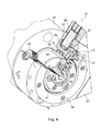
- the second embodiment according to Fig. 4 and 5 is essentially the same as in Fig. 1 to 3 , However, additionally has a built-in storage unit 01 side register adjustment device 32, the axial displacement of the printing cylinder 02, z. B. forme cylinder 02, in particular plate cylinder 02 for Correction of the page register enabled.
- the pin 06 of the forme cylinder 02 is non-rotatably connected to a pin extension 33, which carries a further bearing 34, namely a thrust bearing 34, for example a thrust ball bearing 34, the housing 36 at its outer periphery with a thread 37, in particular a fine thread 37,
- a metric fine thread 37 is provided, which meshes with a corresponding thread 38 of a fixed flange 39 which is rotatably connected to the bearing outer ring 09, in particular screwed.
- a rotation of the housing 36 of the thrust bearing 34 thus causes an axial translational movement of the housing 36 and thus ultimately of the cylinder 02.
- the possible adjustment range here can be about +/- 1.5 mm.
- a ring gear 41 is further mounted, which is rotatable via an additional drive gear 42, in particular spur gear 42 via a drive shaft 43 to the o. G.
- additional drive gear 42 in particular spur gear 42 via a drive shaft 43 to the o. G.
- p is the pitch of the thread 37
- d m is the mean thread diameter
- bearing unit 01 as a rubber cylinder bearing
- the integration of a macroscopic position adjustment for pressure and rest position of the blanket cylinder 02 is possible, see. also WO 2006/061432 A1 ,
Landscapes
- Engineering & Computer Science (AREA)
- Mechanical Engineering (AREA)
- Support Of The Bearing (AREA)
- Rolling Contact Bearings (AREA)
- Rolls And Other Rotary Bodies (AREA)
Applications Claiming Priority (1)
| Application Number | Priority Date | Filing Date | Title |
|---|---|---|---|
| DE200710024767 DE102007024767B4 (de) | 2007-05-26 | 2007-05-26 | Lagereinheit für einen Druckwerkszylinder |
Publications (3)
| Publication Number | Publication Date |
|---|---|
| EP2006097A2 true EP2006097A2 (fr) | 2008-12-24 |
| EP2006097A3 EP2006097A3 (fr) | 2012-01-11 |
| EP2006097B1 EP2006097B1 (fr) | 2012-10-24 |
Family
ID=39877254
Family Applications (1)
| Application Number | Title | Priority Date | Filing Date |
|---|---|---|---|
| EP20080152503 Not-in-force EP2006097B1 (fr) | 2007-05-26 | 2008-03-10 | Unité de support pour un cylindre d'impression d'une machine d'impression |
Country Status (2)
| Country | Link |
|---|---|
| EP (1) | EP2006097B1 (fr) |
| DE (1) | DE102007024767B4 (fr) |
Cited By (1)
| Publication number | Priority date | Publication date | Assignee | Title |
|---|---|---|---|---|
| DE102009002899B3 (de) * | 2009-05-07 | 2010-06-24 | Koenig & Bauer Aktiengesellschaft | Axialeinstellvorrichtung eines Zylinders und ein Verfahren zur Montage einer Axialeinstellvorrichtung eines Zylinders |
Families Citing this family (4)
| Publication number | Priority date | Publication date | Assignee | Title |
|---|---|---|---|---|
| DE102009046538B4 (de) | 2009-11-09 | 2014-06-05 | Koenig & Bauer Aktiengesellschaft | Vorrichtungen und Verfahren zur Schwingungsreduktion |
| DE102010026204A1 (de) | 2010-07-02 | 2012-01-05 | Fakultät Ingenieurwissenschaften und Informatik Fachhochschule Onsabrück | Verfahren sowie Vorrichtung zur Kompensation von über den Umfang eines rotierenden insbesondere zylindrischen, Bauteils, insbesondere einer Walze, periodisch wiederkehrenden Störanregungen sowie Verfahren zur Bestimmung der Oberflächenstruktur eines ringförmigen Profils zur Kompensation der Störanregungen |
| CN103825396B (zh) * | 2014-01-03 | 2016-08-17 | 重庆大学 | 电主轴振动主动控制装置 |
| CN113531041B (zh) * | 2021-07-30 | 2022-06-28 | 山东大学 | 堆叠型压电陶瓷减振环 |
Citations (6)
| Publication number | Priority date | Publication date | Assignee | Title |
|---|---|---|---|---|
| JPH11170474A (ja) | 1997-12-05 | 1999-06-29 | Toshiba Mach Co Ltd | 印刷機のショックマーク防止装置 |
| DE20011948U1 (de) | 2000-07-10 | 2000-12-07 | Skf Gmbh, 97421 Schweinfurt | Lageranordnung |
| WO2001050035A1 (fr) | 1999-12-31 | 2001-07-12 | Koenig & Bauer Aktiengesellschaft | Procede et dispositif pour la compensation de vibrations de composants rotatifs |
| WO2004016431A1 (fr) | 2002-07-19 | 2004-02-26 | Koenig & Bauer Aktiengesellschaft | Procede et dispositif pour reduire les vibrations au niveaux d'elements rotatifs et element rotatif correspondant amorti en vibrations |
| WO2006061432A1 (fr) | 2004-12-10 | 2006-06-15 | Koenig & Bauer Aktiengesellschaft | Procede et dispositifs pour reduire les vibrations |
| DE102005058787A1 (de) | 2004-12-10 | 2006-07-13 | Koenig & Bauer Ag | Verfahren und Vorrichtung zur Schwingungsreduktion |
Family Cites Families (2)
| Publication number | Priority date | Publication date | Assignee | Title |
|---|---|---|---|---|
| DE10107135A1 (de) * | 2001-02-15 | 2002-08-29 | Windmoeller & Hoelscher | Rollendruckmaschine sowie Verfahren zur Schwingungsdämpfung hieran |
| DE10236865A1 (de) * | 2002-08-12 | 2004-02-26 | Koenig & Bauer Ag | Zylinder in einer Druckeinheit mit mindestens einem Kanal mit mindestens einer Haltevorrichtung |
-
2007
- 2007-05-26 DE DE200710024767 patent/DE102007024767B4/de not_active Expired - Fee Related
-
2008
- 2008-03-10 EP EP20080152503 patent/EP2006097B1/fr not_active Not-in-force
Patent Citations (6)
| Publication number | Priority date | Publication date | Assignee | Title |
|---|---|---|---|---|
| JPH11170474A (ja) | 1997-12-05 | 1999-06-29 | Toshiba Mach Co Ltd | 印刷機のショックマーク防止装置 |
| WO2001050035A1 (fr) | 1999-12-31 | 2001-07-12 | Koenig & Bauer Aktiengesellschaft | Procede et dispositif pour la compensation de vibrations de composants rotatifs |
| DE20011948U1 (de) | 2000-07-10 | 2000-12-07 | Skf Gmbh, 97421 Schweinfurt | Lageranordnung |
| WO2004016431A1 (fr) | 2002-07-19 | 2004-02-26 | Koenig & Bauer Aktiengesellschaft | Procede et dispositif pour reduire les vibrations au niveaux d'elements rotatifs et element rotatif correspondant amorti en vibrations |
| WO2006061432A1 (fr) | 2004-12-10 | 2006-06-15 | Koenig & Bauer Aktiengesellschaft | Procede et dispositifs pour reduire les vibrations |
| DE102005058787A1 (de) | 2004-12-10 | 2006-07-13 | Koenig & Bauer Ag | Verfahren und Vorrichtung zur Schwingungsreduktion |
Cited By (1)
| Publication number | Priority date | Publication date | Assignee | Title |
|---|---|---|---|---|
| DE102009002899B3 (de) * | 2009-05-07 | 2010-06-24 | Koenig & Bauer Aktiengesellschaft | Axialeinstellvorrichtung eines Zylinders und ein Verfahren zur Montage einer Axialeinstellvorrichtung eines Zylinders |
Also Published As
| Publication number | Publication date |
|---|---|
| EP2006097B1 (fr) | 2012-10-24 |
| EP2006097A3 (fr) | 2012-01-11 |
| DE102007024767A1 (de) | 2008-11-27 |
| DE102007024767B4 (de) | 2010-06-24 |
Similar Documents
| Publication | Publication Date | Title |
|---|---|---|
| EP1991419B1 (fr) | Groupes d'impression d'une machine à imprimer | |
| EP1609908B1 (fr) | Procédé et dispositif pour réduire des vibrations de flexion à au moins un cylindre rotatif d`une machine d`usinage et machine d`usinage | |
| EP2404720B1 (fr) | Dispositif d'estampillage rotatif de produits plats à plusieurs couches | |
| EP2006097B1 (fr) | Unité de support pour un cylindre d'impression d'une machine d'impression | |
| EP1736698A2 (fr) | Dispositif pour raccorder un composant rotatif d'une machine d'impression pour transmettre du fluide sous pression | |
| EP1820643A2 (fr) | Procédé destiné à la réduction de vibrations | |
| EP1819513B1 (fr) | Dispositif pour reduire les vibrations | |
| DE102005047661B4 (de) | Antrieb eines rotierenden Bauteils einer Druckmaschine | |
| EP0722831B1 (fr) | Procédé et arrangement pour un moteur électrique pour entraíner un corps de rotation, en particulier un cylindre d'imprimerie | |
| EP3664998B1 (fr) | Presse | |
| DE102019121755A1 (de) | Mehrteiliges Stellelement | |
| DE10327490B4 (de) | Druckeinheit einer Rotationsdruckmaschine | |
| EP2762314B1 (fr) | Cylindre rotatif | |
| DE102005058787B4 (de) | Verfahren und Vorrichtung zur Schwingungsreduktion | |
| DE4406572B4 (de) | Rotationsdruckmaschine | |
| WO2013075766A1 (fr) | Groupe d'impression flexographique avec système de levier coudé | |
| DE102005052497B4 (de) | Antrieb eines Zylinders einer Druckmaschine | |
| DE102005008982B3 (de) | Vorrichtungen zum registerhaltigen Ausrichten zumindest einer Druckplatte auf einem Plattenzylinder | |
| DE102006003006B4 (de) | Verfahren zum Einstellen einer Druck-An-Stellung | |
| DE102005058786A1 (de) | Verfahren und eine Vorrichtung zur Schwingungsreduktion eines Zylinders | |
| DE102008041904A1 (de) | Verfahren zur Kontrolle der Rotationskörpereinstellung | |
| DE102007033589B3 (de) | Vorrichtung zum seitlichen Ausrichten mindestens eines einem Zylinder einer Druckmaschine zuzuführenden Aufzugs | |
| WO2013029700A1 (fr) | Machine à imprimer et dispositif d'appui pour cylindre de machine à imprimer | |
| DE102023127980A1 (de) | Elektromechanische Rahmenbremse | |
| DE102004022775B4 (de) | Anordnung eines Elektromotors zum Antrieb eines Drehkörpers |
Legal Events
| Date | Code | Title | Description |
|---|---|---|---|
| PUAI | Public reference made under article 153(3) epc to a published international application that has entered the european phase |
Free format text: ORIGINAL CODE: 0009012 |
|
| AK | Designated contracting states |
Kind code of ref document: A2 Designated state(s): AT BE BG CH CY CZ DE DK EE ES FI FR GB GR HR HU IE IS IT LI LT LU LV MC MT NL NO PL PT RO SE SI SK TR |
|
| AX | Request for extension of the european patent |
Extension state: AL BA MK RS |
|
| PUAL | Search report despatched |
Free format text: ORIGINAL CODE: 0009013 |
|
| AK | Designated contracting states |
Kind code of ref document: A3 Designated state(s): AT BE BG CH CY CZ DE DK EE ES FI FR GB GR HR HU IE IS IT LI LT LU LV MC MT NL NO PL PT RO SE SI SK TR |
|
| AX | Request for extension of the european patent |
Extension state: AL BA MK RS |
|
| RIC1 | Information provided on ipc code assigned before grant |
Ipc: B41F 13/26 20060101ALI20111206BHEP Ipc: B41F 13/24 20060101AFI20111206BHEP Ipc: B41F 13/30 20060101ALI20111206BHEP |
|
| 17P | Request for examination filed |
Effective date: 20111220 |
|
| GRAP | Despatch of communication of intention to grant a patent |
Free format text: ORIGINAL CODE: EPIDOSNIGR1 |
|
| RTI1 | Title (correction) |
Free format text: BEARING UNIT FOR A PRINTING CYLINDER IN A PRINTING MACHINE |
|
| GRAS | Grant fee paid |
Free format text: ORIGINAL CODE: EPIDOSNIGR3 |
|
| AKX | Designation fees paid |
Designated state(s): AT BE BG CH CY CZ DE DK EE ES FI FR GB GR HR HU IE IS IT LI LT LU LV MC MT NL NO PL PT RO SE SI SK TR |
|
| GRAA | (expected) grant |
Free format text: ORIGINAL CODE: 0009210 |
|
| AK | Designated contracting states |
Kind code of ref document: B1 Designated state(s): AT BE BG CH CY CZ DE DK EE ES FI FR GB GR HR HU IE IS IT LI LT LU LV MC MT NL NO PL PT RO SE SI SK TR |
|
| REG | Reference to a national code |
Ref country code: GB Ref legal event code: FG4D Free format text: NOT ENGLISH |
|
| REG | Reference to a national code |
Ref country code: CH Ref legal event code: EP |
|
| REG | Reference to a national code |
Ref country code: AT Ref legal event code: REF Ref document number: 580679 Country of ref document: AT Kind code of ref document: T Effective date: 20121115 |
|
| REG | Reference to a national code |
Ref country code: IE Ref legal event code: FG4D Free format text: LANGUAGE OF EP DOCUMENT: GERMAN |
|
| REG | Reference to a national code |
Ref country code: DE Ref legal event code: R096 Ref document number: 502008008477 Country of ref document: DE Effective date: 20121220 |
|
| REG | Reference to a national code |
Ref country code: NL Ref legal event code: VDEP Effective date: 20121024 |
|
| PG25 | Lapsed in a contracting state [announced via postgrant information from national office to epo] |
Ref country code: NL Free format text: LAPSE BECAUSE OF FAILURE TO SUBMIT A TRANSLATION OF THE DESCRIPTION OR TO PAY THE FEE WITHIN THE PRESCRIBED TIME-LIMIT Effective date: 20121024 Ref country code: FI Free format text: LAPSE BECAUSE OF FAILURE TO SUBMIT A TRANSLATION OF THE DESCRIPTION OR TO PAY THE FEE WITHIN THE PRESCRIBED TIME-LIMIT Effective date: 20121024 Ref country code: IS Free format text: LAPSE BECAUSE OF FAILURE TO SUBMIT A TRANSLATION OF THE DESCRIPTION OR TO PAY THE FEE WITHIN THE PRESCRIBED TIME-LIMIT Effective date: 20130224 Ref country code: NO Free format text: LAPSE BECAUSE OF FAILURE TO SUBMIT A TRANSLATION OF THE DESCRIPTION OR TO PAY THE FEE WITHIN THE PRESCRIBED TIME-LIMIT Effective date: 20130124 Ref country code: HR Free format text: LAPSE BECAUSE OF FAILURE TO SUBMIT A TRANSLATION OF THE DESCRIPTION OR TO PAY THE FEE WITHIN THE PRESCRIBED TIME-LIMIT Effective date: 20121024 Ref country code: SE Free format text: LAPSE BECAUSE OF FAILURE TO SUBMIT A TRANSLATION OF THE DESCRIPTION OR TO PAY THE FEE WITHIN THE PRESCRIBED TIME-LIMIT Effective date: 20121024 Ref country code: ES Free format text: LAPSE BECAUSE OF FAILURE TO SUBMIT A TRANSLATION OF THE DESCRIPTION OR TO PAY THE FEE WITHIN THE PRESCRIBED TIME-LIMIT Effective date: 20130204 |
|
| PG25 | Lapsed in a contracting state [announced via postgrant information from national office to epo] |
Ref country code: PL Free format text: LAPSE BECAUSE OF FAILURE TO SUBMIT A TRANSLATION OF THE DESCRIPTION OR TO PAY THE FEE WITHIN THE PRESCRIBED TIME-LIMIT Effective date: 20121024 Ref country code: GR Free format text: LAPSE BECAUSE OF FAILURE TO SUBMIT A TRANSLATION OF THE DESCRIPTION OR TO PAY THE FEE WITHIN THE PRESCRIBED TIME-LIMIT Effective date: 20130125 Ref country code: LV Free format text: LAPSE BECAUSE OF FAILURE TO SUBMIT A TRANSLATION OF THE DESCRIPTION OR TO PAY THE FEE WITHIN THE PRESCRIBED TIME-LIMIT Effective date: 20121024 Ref country code: CY Free format text: LAPSE BECAUSE OF FAILURE TO SUBMIT A TRANSLATION OF THE DESCRIPTION OR TO PAY THE FEE WITHIN THE PRESCRIBED TIME-LIMIT Effective date: 20121024 Ref country code: SI Free format text: LAPSE BECAUSE OF FAILURE TO SUBMIT A TRANSLATION OF THE DESCRIPTION OR TO PAY THE FEE WITHIN THE PRESCRIBED TIME-LIMIT Effective date: 20121024 Ref country code: PT Free format text: LAPSE BECAUSE OF FAILURE TO SUBMIT A TRANSLATION OF THE DESCRIPTION OR TO PAY THE FEE WITHIN THE PRESCRIBED TIME-LIMIT Effective date: 20130225 |
|
| PG25 | Lapsed in a contracting state [announced via postgrant information from national office to epo] |
Ref country code: DK Free format text: LAPSE BECAUSE OF FAILURE TO SUBMIT A TRANSLATION OF THE DESCRIPTION OR TO PAY THE FEE WITHIN THE PRESCRIBED TIME-LIMIT Effective date: 20121024 Ref country code: SK Free format text: LAPSE BECAUSE OF FAILURE TO SUBMIT A TRANSLATION OF THE DESCRIPTION OR TO PAY THE FEE WITHIN THE PRESCRIBED TIME-LIMIT Effective date: 20121024 Ref country code: BG Free format text: LAPSE BECAUSE OF FAILURE TO SUBMIT A TRANSLATION OF THE DESCRIPTION OR TO PAY THE FEE WITHIN THE PRESCRIBED TIME-LIMIT Effective date: 20130124 Ref country code: CZ Free format text: LAPSE BECAUSE OF FAILURE TO SUBMIT A TRANSLATION OF THE DESCRIPTION OR TO PAY THE FEE WITHIN THE PRESCRIBED TIME-LIMIT Effective date: 20121024 Ref country code: EE Free format text: LAPSE BECAUSE OF FAILURE TO SUBMIT A TRANSLATION OF THE DESCRIPTION OR TO PAY THE FEE WITHIN THE PRESCRIBED TIME-LIMIT Effective date: 20121024 |
|
| PG25 | Lapsed in a contracting state [announced via postgrant information from national office to epo] |
Ref country code: RO Free format text: LAPSE BECAUSE OF FAILURE TO SUBMIT A TRANSLATION OF THE DESCRIPTION OR TO PAY THE FEE WITHIN THE PRESCRIBED TIME-LIMIT Effective date: 20121024 Ref country code: IT Free format text: LAPSE BECAUSE OF FAILURE TO SUBMIT A TRANSLATION OF THE DESCRIPTION OR TO PAY THE FEE WITHIN THE PRESCRIBED TIME-LIMIT Effective date: 20121024 |
|
| PLBE | No opposition filed within time limit |
Free format text: ORIGINAL CODE: 0009261 |
|
| STAA | Information on the status of an ep patent application or granted ep patent |
Free format text: STATUS: NO OPPOSITION FILED WITHIN TIME LIMIT |
|
| BERE | Be: lapsed |
Owner name: KOENIG & BAUER A.G. Effective date: 20130331 |
|
| 26N | No opposition filed |
Effective date: 20130725 |
|
| PG25 | Lapsed in a contracting state [announced via postgrant information from national office to epo] |
Ref country code: MC Free format text: LAPSE BECAUSE OF NON-PAYMENT OF DUE FEES Effective date: 20130331 |
|
| REG | Reference to a national code |
Ref country code: CH Ref legal event code: PL |
|
| GBPC | Gb: european patent ceased through non-payment of renewal fee |
Effective date: 20130310 |
|
| REG | Reference to a national code |
Ref country code: DE Ref legal event code: R097 Ref document number: 502008008477 Country of ref document: DE Effective date: 20130725 |
|
| REG | Reference to a national code |
Ref country code: FR Ref legal event code: ST Effective date: 20131129 |
|
| REG | Reference to a national code |
Ref country code: IE Ref legal event code: MM4A |
|
| REG | Reference to a national code |
Ref country code: DE Ref legal event code: R119 Ref document number: 502008008477 Country of ref document: DE Effective date: 20131001 |
|
| PG25 | Lapsed in a contracting state [announced via postgrant information from national office to epo] |
Ref country code: GB Free format text: LAPSE BECAUSE OF NON-PAYMENT OF DUE FEES Effective date: 20130310 Ref country code: DE Free format text: LAPSE BECAUSE OF NON-PAYMENT OF DUE FEES Effective date: 20131001 Ref country code: FR Free format text: LAPSE BECAUSE OF NON-PAYMENT OF DUE FEES Effective date: 20130402 Ref country code: IE Free format text: LAPSE BECAUSE OF NON-PAYMENT OF DUE FEES Effective date: 20130310 Ref country code: LI Free format text: LAPSE BECAUSE OF NON-PAYMENT OF DUE FEES Effective date: 20130331 Ref country code: BE Free format text: LAPSE BECAUSE OF NON-PAYMENT OF DUE FEES Effective date: 20130331 Ref country code: CH Free format text: LAPSE BECAUSE OF NON-PAYMENT OF DUE FEES Effective date: 20130331 |
|
| REG | Reference to a national code |
Ref country code: AT Ref legal event code: MM01 Ref document number: 580679 Country of ref document: AT Kind code of ref document: T Effective date: 20130310 |
|
| PG25 | Lapsed in a contracting state [announced via postgrant information from national office to epo] |
Ref country code: LT Free format text: LAPSE BECAUSE OF FAILURE TO SUBMIT A TRANSLATION OF THE DESCRIPTION OR TO PAY THE FEE WITHIN THE PRESCRIBED TIME-LIMIT Effective date: 20121024 Ref country code: MT Free format text: LAPSE BECAUSE OF FAILURE TO SUBMIT A TRANSLATION OF THE DESCRIPTION OR TO PAY THE FEE WITHIN THE PRESCRIBED TIME-LIMIT Effective date: 20121024 |
|
| PG25 | Lapsed in a contracting state [announced via postgrant information from national office to epo] |
Ref country code: AT Free format text: LAPSE BECAUSE OF NON-PAYMENT OF DUE FEES Effective date: 20130310 |
|
| PG25 | Lapsed in a contracting state [announced via postgrant information from national office to epo] |
Ref country code: TR Free format text: LAPSE BECAUSE OF FAILURE TO SUBMIT A TRANSLATION OF THE DESCRIPTION OR TO PAY THE FEE WITHIN THE PRESCRIBED TIME-LIMIT Effective date: 20121024 |
|
| PG25 | Lapsed in a contracting state [announced via postgrant information from national office to epo] |
Ref country code: HU Free format text: LAPSE BECAUSE OF FAILURE TO SUBMIT A TRANSLATION OF THE DESCRIPTION OR TO PAY THE FEE WITHIN THE PRESCRIBED TIME-LIMIT; INVALID AB INITIO Effective date: 20080310 Ref country code: LU Free format text: LAPSE BECAUSE OF NON-PAYMENT OF DUE FEES Effective date: 20130310 |