EP2006140B1 - Systeme d'ouverture/fermeture pour panneau de toit et cable de commande separe utilise pour celui-ci - Google Patents
Systeme d'ouverture/fermeture pour panneau de toit et cable de commande separe utilise pour celui-ci Download PDFInfo
- Publication number
- EP2006140B1 EP2006140B1 EP20070740016 EP07740016A EP2006140B1 EP 2006140 B1 EP2006140 B1 EP 2006140B1 EP 20070740016 EP20070740016 EP 20070740016 EP 07740016 A EP07740016 A EP 07740016A EP 2006140 B1 EP2006140 B1 EP 2006140B1
- Authority
- EP
- European Patent Office
- Prior art keywords
- roof panel
- cable
- locking mechanism
- fully closed
- panel
- Prior art date
- Legal status (The legal status is an assumption and is not a legal conclusion. Google has not performed a legal analysis and makes no representation as to the accuracy of the status listed.)
- Ceased
Links
- 230000007246 mechanism Effects 0.000 claims abstract description 225
- 230000033001 locomotion Effects 0.000 claims description 16
- 230000009467 reduction Effects 0.000 description 9
- 230000003247 decreasing effect Effects 0.000 description 5
- 238000010276 construction Methods 0.000 description 2
- 230000001629 suppression Effects 0.000 description 2
- 230000003796 beauty Effects 0.000 description 1
- 230000005540 biological transmission Effects 0.000 description 1
- 230000002542 deteriorative effect Effects 0.000 description 1
- 230000006872 improvement Effects 0.000 description 1
- 230000037431 insertion Effects 0.000 description 1
- 238000003780 insertion Methods 0.000 description 1
- 230000013011 mating Effects 0.000 description 1
- 230000000149 penetrating effect Effects 0.000 description 1
- 238000007789 sealing Methods 0.000 description 1
- 239000003566 sealing material Substances 0.000 description 1
- 238000003466 welding Methods 0.000 description 1
Images






Classifications
-
- B—PERFORMING OPERATIONS; TRANSPORTING
- B60—VEHICLES IN GENERAL
- B60J—WINDOWS, WINDSCREENS, NON-FIXED ROOFS, DOORS, OR SIMILAR DEVICES FOR VEHICLES; REMOVABLE EXTERNAL PROTECTIVE COVERINGS SPECIALLY ADAPTED FOR VEHICLES
- B60J7/00—Non-fixed roofs; Roofs with movable panels, e.g. rotary sunroofs
- B60J7/185—Locking arrangements
- B60J7/19—Locking arrangements for rigid panels
- B60J7/198—Locking arrangements for rigid panels for locking tonneau covers such as covers for roof storage compartments or for pick-up truck beds
-
- B—PERFORMING OPERATIONS; TRANSPORTING
- B60—VEHICLES IN GENERAL
- B60J—WINDOWS, WINDSCREENS, NON-FIXED ROOFS, DOORS, OR SIMILAR DEVICES FOR VEHICLES; REMOVABLE EXTERNAL PROTECTIVE COVERINGS SPECIALLY ADAPTED FOR VEHICLES
- B60J7/00—Non-fixed roofs; Roofs with movable panels, e.g. rotary sunroofs
- B60J7/08—Non-fixed roofs; Roofs with movable panels, e.g. rotary sunroofs of non-sliding type, i.e. movable or removable roofs or panels, e.g. let-down tops or roofs capable of being easily detached or of assuming a collapsed or inoperative position
- B60J7/12—Non-fixed roofs; Roofs with movable panels, e.g. rotary sunroofs of non-sliding type, i.e. movable or removable roofs or panels, e.g. let-down tops or roofs capable of being easily detached or of assuming a collapsed or inoperative position foldable; Tensioning mechanisms therefor, e.g. struts
- B60J7/14—Non-fixed roofs; Roofs with movable panels, e.g. rotary sunroofs of non-sliding type, i.e. movable or removable roofs or panels, e.g. let-down tops or roofs capable of being easily detached or of assuming a collapsed or inoperative position foldable; Tensioning mechanisms therefor, e.g. struts with a plurality of rigid plate-like elements or rigid non plate-like elements, e.g. with non-slidable, but pivotable or foldable movement
- B60J7/143—Non-fixed roofs; Roofs with movable panels, e.g. rotary sunroofs of non-sliding type, i.e. movable or removable roofs or panels, e.g. let-down tops or roofs capable of being easily detached or of assuming a collapsed or inoperative position foldable; Tensioning mechanisms therefor, e.g. struts with a plurality of rigid plate-like elements or rigid non plate-like elements, e.g. with non-slidable, but pivotable or foldable movement for covering the passenger compartment
- B60J7/145—Non-fixed roofs; Roofs with movable panels, e.g. rotary sunroofs of non-sliding type, i.e. movable or removable roofs or panels, e.g. let-down tops or roofs capable of being easily detached or of assuming a collapsed or inoperative position foldable; Tensioning mechanisms therefor, e.g. struts with a plurality of rigid plate-like elements or rigid non plate-like elements, e.g. with non-slidable, but pivotable or foldable movement for covering the passenger compartment at least two elements being folded in clamp-shell fashion
-
- B—PERFORMING OPERATIONS; TRANSPORTING
- B60—VEHICLES IN GENERAL
- B60J—WINDOWS, WINDSCREENS, NON-FIXED ROOFS, DOORS, OR SIMILAR DEVICES FOR VEHICLES; REMOVABLE EXTERNAL PROTECTIVE COVERINGS SPECIALLY ADAPTED FOR VEHICLES
- B60J7/00—Non-fixed roofs; Roofs with movable panels, e.g. rotary sunroofs
- B60J7/185—Locking arrangements
- B60J7/1855—Locking arrangements for locking or immobilising roof elements when stored
-
- B—PERFORMING OPERATIONS; TRANSPORTING
- B60—VEHICLES IN GENERAL
- B60J—WINDOWS, WINDSCREENS, NON-FIXED ROOFS, DOORS, OR SIMILAR DEVICES FOR VEHICLES; REMOVABLE EXTERNAL PROTECTIVE COVERINGS SPECIALLY ADAPTED FOR VEHICLES
- B60J7/00—Non-fixed roofs; Roofs with movable panels, e.g. rotary sunroofs
- B60J7/185—Locking arrangements
- B60J7/1856—Locking arrangements for interlocking the roof linkage system when deployed
-
- Y—GENERAL TAGGING OF NEW TECHNOLOGICAL DEVELOPMENTS; GENERAL TAGGING OF CROSS-SECTIONAL TECHNOLOGIES SPANNING OVER SEVERAL SECTIONS OF THE IPC; TECHNICAL SUBJECTS COVERED BY FORMER USPC CROSS-REFERENCE ART COLLECTIONS [XRACs] AND DIGESTS
- Y10—TECHNICAL SUBJECTS COVERED BY FORMER USPC
- Y10T—TECHNICAL SUBJECTS COVERED BY FORMER US CLASSIFICATION
- Y10T74/00—Machine element or mechanism
- Y10T74/20—Control lever and linkage systems
- Y10T74/20012—Multiple controlled elements
Definitions
- the present invention relates to a system for holding a roof panel supported by a vehicle body via a link mechanism and capable of operating opening, closing, and moving between a fully closed state where vehicle cabin space is closed and a stored state where the vehicle cabin space is opened and said roof panel is stored in a storage room located in rear side of the vehicle, at the fully closed state and stored state, and a branched driving cable to be used for the system.
- a vehicle with such a configuration that panel members such as a roof panel provided to a vehicle body are made openable, closable, and movable (see Patent Documents 1 , 2 ).
- a roof panel is supported by a vehicle body via a link mechanism and at the same time, the link mechanism is driven by an electric motor so as to allow opening and closing of the roof panel between fully closed state where vehicle cabin space is closed and stored state where vehicle cabin space is opened and the roof panel is stored in the trunk room.
- roof panel automatically openable/closable as mentioned
- lifting of the roof panel occurs by aerodynamic force or vibrations during traveling in fully closed state or at stored state, and looseness is caused due to vibrations during traveling. Therefore, the roof panel should be reliably held to the vehicle body in fully closed state and stored state, and various locking mechanisms are required.
- a roof locking mechanism for holding front edge portion of the roof panel to front header of vehicle body in fully closed state, where vehicle cabin space is closed by the roof panel, is provided.
- the roof panel is held in fully closed state by this roof locking mechanism which is driven by an electric motor via a connecting rod.
- a link locking mechanism for restricting the link mechanism connecting the roof panel and the vehicle body while the roof panel is in fully closed state. In this way, improvement of holding rigidity of the roof panel in fully closed state is attempted by restricting the link mechanism. That is, the link locking mechanism indirectly holds the roof panel by restricting the link mechanism.
- This link locking mechanism is driven via a wire although driving mechanism is unknown.
- a stored state locking mechanism which holds the roof panel in the storage room in stored state where the roof panel is stored in the storage room is provided. In this way, by holding the roof panel in stored state by the stored state locking mechanism, up/down looseness of the roof panel in the storage room at traveling is prevented.
- the stored state locking mechanism is driven by an electric motor via a connecting rod.
- the present invention has been developed in view of the above aspects, and an object of the present invention is to reduce the number of parts for cases where a plurality of locking mechanisms is used.
- the present invention is designed in such that a plurality of locking mechanisms is driven by one driving mechanism using a branched driving cable capable of obtaining two outputs from one input. Locking mechanisms which can function appropriately even if they are driven by one driving mechanism are selected as said plurality of locking mechanisms.
- an object of the invention is a system for opening/closing a roof panel which a roof panel supported by a vehicle body via a link mechanism and is capable of operating opening/closing movement between a fully closed state for closing a vehicle cabin space and a stored state in which the vehicle cabin space is opened and said roof panel is stored in a storage room located in rear side of the vehicle, a fully closed state locking mechanism for holding the roof panel when said roof panel is in fully closed state, and a stored state locking mechanism for holding the roof panel when said roof panel is in stored state.
- the invention is further comprising a driving mechanism associated with a storage room panel adapted for opening and closing said storage room, a branched driving cable having an input cable being driven by said driving mechanism when pulled, a connecting member connected rotatably to the vehicle body with output end of the input cable is connected thereto, a first output cable, an input end of which is connected to the connecting member while an output end of which is connected to said fully closed state locking mechanism, which first output cable transmits a pulling force of the input cable to the fully closed state locking mechanism, and a second output cable, an input end of which is connected to the connecting member while an output end of which is connected to said stored state locking mechanism, which second output cable transmits a pulling force of the input cable to the stored state locking mechanism, where both of said fully closed state locking mechanism and said stored state locking mechanism are driven by said driving mechanism through said branched driving cable.
- said fully closed locking mechanism and stored state locking mechanism can be driven by one input. Specifically, when said input cable is driven while the roof panel is in fully closed state, the fully closed state locking mechanism holds the roof panel. Although the stored state locking mechanism is operated on this occasion, it does not hold the roof panel since the roof panel is not in stored state. Meanwhile, when the input cable is driven while the roof panel is in stored state, the stored state locking mechanism holds the roof panel. Although the fully closed state locking mechanism is operated on this occasion, it does not hold the roof panel since the roof panel is not in fully closed state.
- the fully closed state locking mechanism is a locking mechanism necessary when the roof panel is in fully closed state while the stored state locking mechanism is a locking mechanism necessary when the roof panel is in stored state, and fully closed state and stored state do not occur simultaneously, and therefore one input can drive fully closed state locking mechanism or stored state locking mechanism appropriately as necessary.
- fully closed state locking mechanism and stored state locking mechanism are driven via said branched driving cable, and common use of the driving mechanism is made possible.
- said storage room panel need to be opened/closed inevitably. That is, since said fully closed state locking mechanism and stored state locking mechanism function being interlocked with the storage room panel, such a configuration is used that said fully closed state locking mechanism and stored state locking mechanism are driven by a driving mechanism associated with the storage room panel.
- the driving mechanism shared between the fully closed locking mechanism and the stored state locking mechanism by the branched driving cable is also used as a driving mechanism associated with the storage room panel, thereby reducing the number of parts.
- said storage room panel is provided with a storage room panel locking mechanism for holding the storage room panel when said storage room is closed, said driving mechanism is adapted to drive said storage room panel locking mechanism, and said fully closed state locking mechanism and said stored state locking mechanism are driven synchronously so that both of said mechanisms hold said roof panel and said storage room panel when said storage room panel locking mechanism is holding said storage room panel, while both of said mechanisms release holding of said roof panel and said storage room panel when said storage room panel locking mechanism releases holding of said storage room panel.
- said storage room panel is held in fully closed state by said storage room panel locking mechanism and is brought into fully opened state when the roof panel is moved from fully closed state to stored state or from stored state to fully closed state.
- time required for storing or fully closing the roof panel is preferably shorter. Then, in order to shorten the time required, such a configuration is employed that when said storage room panel locking mechanism releases holding of said storage room panel, said fully closed state locking mechanism and stored state locking mechanism release holding of the roof panel.
- a panel holding of which is released first should start operation having waited for releasing of holding of rest panel, and time required for storing or fully closing the roof panel is lengthened as much as the time for waiting.
- said first output cable is connected to said connecting member at a position away from a rotation center of said connecting member for a predetermined first distance
- said second output cable is connected to said connecting member at a position away from the rotation center of said connecting member for a predetermined second distance
- said input cable is connected to said connecting member at a position away from the rotation center of said connecting member for a predetermined third distance.
- a pulling force input to said input cable can be increased or decreased and then transmitted to the output cable, the output cable can be driven with stroke volume (pulling length) when the input cable is driven being increased or decreased. That is, by adjusting said predetermined first to third distances in said connecting member, pulling force or stroke volume being input can be adjusted depending on each locking mechanism and then output.
- said first to third distances need not necessarily be different, and the same distance may be used.
- the branched driving cable is comprising an input cable driven by a pulling force, a rotatable connecting member connected to an output end of the input cable, a first output cable, an output end of which is connected to the connecting member while an input end of which is connected to a first member to be driven, and a second output cable, an output end of which is connected to the connecting member and input end is connected to a second member to be driven.
- the driving cable for driving two driven members can be structured as one assembly.
- the number of parts of cables can be reduced, thereby suppressing the costs and improving ease of assembly.
- said first output cable is connected to said connecting member at a position away from a rotation center of the connecting member for a predetermined first distance
- said second output cable is connected to said connecting member at a position away from the rotation center of the connecting member for a predetermined second distance
- said input cable is connected to said connecting member at a position away from the rotation center of the connecting member for a predetermined third distance.
- a pulling force input to said input cable can be increased or decreased and then transmitted to the output cable, the output cable can be driven with stroke volume (pulling length) when the input cable is driven being increased or decreased. That is, by adjusting said predetermined first to third distances in said connecting member, pulling force or stroke volume being input can be adjusted depending on each locking mechanism and then output.
- said first to third distances need not necessarily be different, and the same distance may be used.
- said fully closed state locking mechanism and stored state locking mechanism are driven by said branched driving cable, and driving mechanism thereof is made common with the driving mechanism associated with said storage room panel to allow reduction in the number of parts, thereby suppressing costs and improving ease of assembly.
- a driving cable for driving said first driven means and second driven means is composed to be branched construction having one input cable and two output cables (i.e., first output cable and second output cable), and this allows reduction in the number of parts and suppression of costs.
- first output cable and second output cable i.e., first output cable and second output cable
- front side of the vehicle is referred to as “front”
- rear side of the vehicle is referred to as “rear”
- left side of vehicle width direction is referred to as “left”
- right side of vehicle width direction is referred to as "right”.
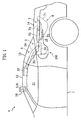
- Fig. 1 shows a vehicle V having a trunk lid relating to the embodiment of the present invention.
- Reference numeral 12 is a roof panel provided to a vehicle body 1
- 13 is a back window panel provided to the vehicle 1
- 14 is a trunk lid for opening/closing a trunk room 15 formed to rear side of the vehicle of vehicle body 1 .
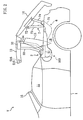
- Said roof panel 12 and back window panel 13 are configured to be openable/closable by the roof panel opening/closing device 2 between fully closed state where vehicle cabin space 11 of the vehicle body 1 is closed as shown in Fig. 1 and stored state (fully opened state) being in the trunk room 15 provided at rear side of the vehicle as shown in Fig. 3 .
- said trunk lid 14 is cofigured to be openable/closable by the trunk lid opening/closing device 6 between fully closed state where the trunk room 15 is closed and fully opened state where the trunk room 15 is opened.
- the trunk lid 14 performs opening/closing operation being interlocked with opening/closing operation of said roof panel 12 and back window panel 13. That is, when said roof panel 12 and back window panel 13 are in fully closed state or stored state, the trunk lid 14 is in fully closed state (see Figs. 1 , 3 ), and when said roof panel 12 and back window panel 13 are performing opening/closing operation from fully closed state to stored state or vice versa, the trunk room 15 remains in opened state (see Fig. 2 ).
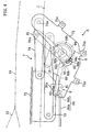
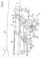
- the trunk lid opening/closing device 6 will be explained. Although the trunk lid opening/closing device 6 is provided at both right and left side with respect to the trunk lid 14 , their configuration is identical, and therefore, explanation will be given for the trunk lid opening/closing device 6 at the left referring to Fig. 4 to Fig. 8 .
- the trunk lid opening/closing device 6 includes a link mechanism 7 for connecting the trunk lid 14 and the vehicle body 1 , a locking mechanism 8 for holding the trunk lid 14 in fully closed state, an electric motor 10 (not shown in Figs. 5 to 7 ) for driving the link mechanism 7 and the locking mechanism 8 , and a transmitting mechanism 9 for transmitting a driving force of the electric motor 10 to the link mechanism 7 , causes the trunk lid 14 to perform opening/closing operation between fully closed state and fully opened state, and at the same time, holds the trunk lid 14 to the vehicle body in fully closed state.
- Said link mechanism 7 includes a base bracket 71 provided to the vehicle body 1 , a lid side bracket 72 provided to the trunk lid 14, and a front connecting link 73 and a rear connecting link 74 for connecting the base bracket 71 and the lid side bracket 72 .
- Said base bracket 71 includes mounting brackets 71a , 71a , ... , and these mounting brackets 71a , 71a , ... are attached to the side body of the vehicle body 1 from the inside of the vehicle cabin.
- Lid side end of said front connecting link 73 is rotatably connected to the lid side bracket 72 and vehicle side end of said front connecting link 73 is rotatably connected to the base bracket 71 .
- lid side end of said rear connecting link 74 is rotatably connected to the lid side bracket 72 and vehicle side end of said rear connecting link 74 is rotatably connected to the base bracket 71 at backward position than the front connecting link member 73 .
- the base bracket 71 , the lid side bracket 72 , the front connecting link member 73 , and rear connecting link 74 constitute so-called four-jointed link mechanism, and rotation of the front connecting link 73 and the rear connecting link 74 about each of vehicle side end causes the trunk lid 14 to perform opening/closing operation.
- Said transmitting mechanism 9 includes a driving link 91 one end of which is connected to said rear connecting link 74 , a sector gear 92 rotatably driven being connected to the electric motor 10 , and a connecting pin 93 for connecting other end of the driving link 91 and the sector gear 92 , and is so composed that transmitting state where driving force of the electric motor 10 is transmitted to the link mechanism 7 and non-transmitting state where the driving force is not transmitted to the link mechanism 7 are switchable.
- One end of said driving link 91 is rotatably connected to said rear connecting link 74 at a connection portion 91a , while to other end is penetrated an inserting hole 91b (see Fig. 8 ) through which said connecting pin 93 is passed.
- a gear portion 92a mating with an output gear (not shown) provided to an output shaft of said electric motor 10 and a connection portion 92b to which other end of said driving link 91 is connected.
- Said gear portion 92a has gear ratio to reduce driving force of the electric motor 10 with respect to the output gear, i.e., the sector gear 92 functions also as a reduction gear.
- To said connection portion 92b is penetrated a fitting hole 92c in oblong shape extending in radial direction with respect to center of rotation of the sector gear 92 .
- the driving link 91 is rotatably connected to the sector gear 92 and is displaceably connected in the direction of extension of the oblong hole of the fitting hole 92c .
- the connecting pin 93 is rotatably provided to the driving link 91 by insertion through the inserting hole 91b of the driving link 91, sthe connecting pin 93 may be fixed to the driving link 91 by welding.
- the fitting hole 92c need not be penetrated necessarily, and any configuration with closed bottom may be used as long as the connecting pin 93 can be fit thereto.
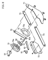
- the driving link 91 and the sector gear 92 connected via the connecting pin 93 are grasped by a guide outer 75 (shown in Fig. 8 only) and a guide inner 76 (shown in Fig. 8 only) provided opposedly each other as shown in Fig. 8 .
- a guide outer 75 shown in Fig. 8 only
- a guide inner 76 shown in Fig. 8 only
- an outer guide groove 75a is formed to said guide outer 75, and at the same time, an inner guide groove 76a having identical profile of the outer guide groove 75a as opposed thereto is formed to the guide inner 76.
- a pair of the outer guide groove 75a and the inner guide groove 76a constitutes one guide portion 94.
- the outer guide groove 75a and the inner guide groove 76a have a groove width which is identical to or slightly broader than the outside diameter of the connecting pin 93 and allows fitting of the connecting pin 93 in the groove 76a.
- the guide portion 94 (outer guide groove 75a and inner guide groove 76a ) has a curved shape from one end located at front lower side to other end located at rear upper side, and a non-transmitting guide portion 94a for not transmitting the driving force of the electric motor 10 to the link mechanism 7 and a transmitting guide portion 94b for transmitting the driving force of the electric motor 10 to the link mechanism 7 are continuous with each other at a switching point 94c .
- Said non-transmitting guide portion 94a is formed between one end at front lower side and the switching point 94c , and forms an arc C1 (shown in Fig. 4 only) which is drawn around the connection portion 91a in the fully closed state of trunk lid 14 , to which the driving link 91 and the rear connecting link 74 are connected, and passes the the connecting pin 93 .
- the driving link 91 simply rotates about the connection portion 91a as shown in Figs. 4 , 5 , while the connection portion 91a is not displaced.
- the rear connecting link 74 does not move and the trunk lid 14 remains motionless in fully closed state. That is, the transmitting mechanism 9 is in non-transmitting state where driving force of the electric motor 10 is not transmitted to the link mechanism 7 while the connecting pin 93 is guided along the non-transmitting guide portion 94a.
- Said transmitting guide portion 94b is formed between the switching point 94c and other end at rear upper side, and has a profile of arc C2 (shown in Fig. 4 only) passing on the connecting pin 93 while rotation center of the sector gear 92 is centered.
- the driving link 91 moves so as to displace the connection portion 91a of the driving link 91 and the rear connecting link 74 as shown in Fig. 6 , and causes the rear connecting link 74 to rotate around a vehicle side end 74a .
- the trunk lid 14 performs opening/closing operation by the link mechanism 7 (see Figs. 1 to 3 ). That is, the transmitting mechanism 9 is in transmitting state for transmitting driving force of the electric motor 10 to the link mechanism 7 while guiding the connecting pin 93 along the transmitting guide portion 94b .
- Said locking mechanism 8 includes, as shown in Fig. 4 , a hook 81 rotatably provided to said base bracket 71 , an engaging pin 82 provided to said lid side bracket 72 and engages with the hook 81 , and the lock transmitting link 83 for transmitting driving force of the electric motor 10 to the hook 81 , and holds the trunk lid 14 in fully closed state by engaging the hook 81 with the engaging pin 82 when the trunk lid 14 is in fully closed state.
- a hook portion 81a engaging with said engaging pin 82 is formed to said hook 81.
- lock transmitting link 83 is rotatably connected to the connection portion 92b of said sector gear 92 and other end is rotatably connected to said hook 81 to transmit rotating motion of the sector gear 92 to the hook 81 .
- the lock transmitting link 83 causes the hook 81 to rotate in the direction engaging with the engaging pin 82 (counterclockwise in Fig. 4 ) when the sector gear 92 drives the connecting pin 93 from switching point 94c to one end side direction along non-transmitting guide portion 94a of the guide portion 94 (clockwise in Fig. 4 ), and causes the hook 81 to rotate in the direction disengaging from the engaging pin 82 (clockwise in Fig.
- an input end of an inner cable 84b of an input cable 84 which will be dealt with later.
- the connecting pin 93 is, as shown in Fig. 4 , located at one end of front lower side of the non-transmitting guide portion 94a of the guide portion 94. Since one end of the non-transmitting guide portion 94a side of the guide portion 94 is located at farthest position from center of rotation of the sector gear 92 in the guide portion 94 , the connecting pin 93 is located at outer end of the fitting hole 92c .
- the hook portion 81a of the hook 81 is engaged with the engaging pin 82 of the lid side bracket 72 , thereby holding the trunk lid 14 in fully closed state.
- the connecting pin 93 moves the non-transmitting guide portion 94a of the guide portion 94 from one end side to the switching point 94c side in accordance with rotation of the sector gear 92 . Since this non-transmitting guide portion 94a has arc C1 profile around the connection portion 91a of the driving link 91 and the rear connecting link 74 when the trunk lid 14 is fully closed, the driving link 91 simply rotates about the connection portion 91a as long as the connecting pin 93 is being guided to the non-transmitting guide portion 94a .
- connection portion 91a does not displace, the rear connecting link 74 does not move, and the trunk lid 14 remains motionless in fully closed state.
- the connecting pin 93 moves relatively in the fitting hole 92c from outer end side to inner end side as the connecting pin 93 moves along the non-transmitting guide portion 94a toward the transmitting guide portion 94b.
- the connecting pin 93 will be located at inner end of the fitting hole 92c .
- the hook 81 starts rotation from a state where the hook portion 81a is engaged with the engaging pin 82 to disengaging direction, and when the connecting pin 93 comes to the position of the switching point 94c of the guide portion 94 , engagement with the engaging pin 82 is completely released. That is, the locking mechanism 8 performs unlocking operation when the transmitting mechanism 9 is in non-transmitting state.
- the connecting pin 93 When the sector gear 92 is further driven counterclockwise by driving the electric motor 10 , as shown in Fig. 6 , the connecting pin 93 will be guided along the transmitting guide portion 94b of the guide portion 94 . Then, the connecting pin 93 moves being deviated from the arc C1 profile around said connection portion 91a , and therefore, the driving link 91 not only rotates about the connection portion 91a , but also moves to displace the connection portion 91a upwardly. As a result, the rear connecting link 74 rotates about the vehicle side end 74a and accordingly, the trunk lid 14 starts opening. On this occasion, the trunk lid 14 is able to perform opening/closing operation since the locking mechanism 8 is in unlocked state.
- the electric motor 10 is driven in the reverse direction (clockwise in the figure) of the direction when the trunk lid 14 is brought into fully opened state.
- the connecting pin 93 then moves on the transmitting guide portion 94b from other end side to switching point 94c side.
- the driving link 91 displaces the connection portion 91a in accordance with movement of the connecting pin 93 , and rotates the rear connecting link 74 about the vehicle side end 74a in the direction to close the trunk lid 14 .
- the trunk lid 14 starts closing.
- the trunk lid 14 When the connecting pin 93 arrives at the switching point 94c of the guide portion 94, the trunk lid 14 is in fully closed state where the trunk room 15 is fully closed (see Fig. 5 ).
- the connecting pin 93 passes the switching point 94c and moves along the non-transmitting guide portion 94a from switching point 94c side to one end side, i.e., when the transmitting mechanism 9 is in non-transmitting state, the hook portion 81a of said hook 81 starts engagement with the engaging pin 82 .
- the connecting pin 93 reach one end of the non-transmitting guide portion 94a , the hook portion 81a of said hook 81 is fully engaged with the engaging pin 82 to become locked state.
- the driving link 91 simply rotates about the connection portion 91a as long as the connecting pin 93 is moving along the non-transmitting guide portion 94a and the connection portion 91a is not displaced, and therefore, the trunk lid 14 remains motionless in fully closed state. That is, the locking mechanism 8 performs locking operation while the transmitting mechanism 9 is in non-transmitting state.
- the trunk lid opening/closing device 6 drives the locking mechanism 8 while the trunk lid 14 remains motionless to cause locking or unlocking operation.
- the connecting pin 93 is moved along the transmitting guide portion 94b , it causes the trunk lid 14 to perform opening/closing operation.
- the roof panel opening/closing device 2 is provided at both right and left side with respect to the roof panel 12 and the back window panel 13 and their configuration is identical, and therefore, explanation will be given for the roof panel opening/closing device 2 at the left referring to Fig. 9 to Fig. 15 .
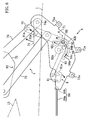
- the roof panel opening/closing device 2 includes, as shown in Fig. 9 , the link mechanism 3 for connecting the roof panel 12 , the back window panel 13 , and vehicle body 1 (see Fig. 1 ), the electric motor 4 (shown in Fig. 9 only) for driving the link mechanism 3 , a link restricting mechanism 500 for restricting the link mechanism 3 when the roof panel 12 and the back window panel 13 are in fully closed state, and a stored state locking mechanism 510 for holding the roof panel 12 when the roof panel 12 and the back window panel 13 are in stored state.
- the roof panel opening/closing device 2 causes the roof panel 12 and the back window panel 13 to perform opening/closing operation between fully closed state and stored state, restricts the link mechanism 3 in the fully closed state, and at the same time, holds the roof panel 12 in the stored state.
- a sealing material (not shown) is provided at periphery of said roof panel 12 and the back window panel 13 in order to maintain air tightness of the vehicle cabin space 11 in fully closed state.
- Said link mechanism 3 includes, as shown in FIGS 1 to 3 , a base bracket 31 provided to the vehicle body 1 , a panel side bracket 32 provided to the roof panel 12 , and the front connecting link 33 and the rear connecting link 34 for connecting the base bracket 31 and the panel side bracket 32 .
- a panel side end of said front connecting link 33 is rotatably connected to the panel side bracket 32 and a vehicle body side end of said front connecting link 33 is rotatably connected to the base bracket 31 .
- a panel side end of said rear connecting link 34 is rotatably connected to the panel side bracket 32 and a vehicle body side end of said rear connecting link 34 is rotatably connected to the base bracket 31 at backward position than the front connecting link member 33.
- the back window panel 13 is provided to the rear connecting link 34 .
- the base bracket 31 , the panel side bracket 32 , the front connecting link 33 , and the rear connecting link 34 constitute so-called four-jointed link mechanism.
- Said electric motor 14 is, as shown in Fig. 9 , provided to vehicle body side end of the front connecting link 33.
- a reduction gear 33a is provided to the vehicle body side end of the front connecting link 33
- the electric motor 4 is provided to said base bracket 31 in such that an output gear 4a provided to the output shaft thereof mates with the reduction gear 33a .
- driving force of the electric motor 4 is reduced and transmitted to the front connecting link 33 to rotate the front connecting link 33 about vehicle body side end thereof.
- the link mechanism 3 is driven to perform opening/closing operation of the roof panel 12 and the back window panel 13 .
- roof panel 12 and back window panel 13 (hereafter also referred to as roof panel 12 and the like). Since the roof panel 12 and the like are opened and closed being interlocked with opening/closing operation of the trunk lid 14 , interlocking with the trunk lid 14 is also explained.
- the front connecting link 33 and the rear connecting link 34 are inclined forward being overlapped each other in the side elevation, and the roof panel 12 and the like are in fully closed state where the vehicle cabin space 11 is closed.
- the roof panel 12 is held by a locking mechanism (not shown) with respect to a front header 16 while front edge portion is in contact with the front header 16 .
- rear edge portion of the roof panel 12 and front edge portion of the back window panel 13 are in contact via the sealing member.
- the trunk lid 14 is also in fully closed state.
- the trunk lid 14 performs opening/closing in accordance with the movements of the roof panel 12 and the back window panel 13 .
- the trunk lid 14 in order to avoid interference with opening/closing operation of the roof panel 12 and the like, when the roof panel 12 and the like move up to a position, where the roof panel 12 and the like are overlapped on opening/closing track of the trunk lid 14, the trunk lid 14 is in opened state up to a position where it does not interfere with opening/closing track of the roof panel 12 and the like.
- the front connecting link 33 and the rear connecting link 34 are inclined backward being overlapped each other in the side elevation, and are in the trunk room 15 while the roof panel 12 and the back window panel 13 are folded and overlapped up and down.
- the trunk lid 14 is closed gradually following the roof panel 12 and the like being retracted into the trunk room 15, and when the roof panel 12 and the like are stored wholly in the trunk room 15, the trunk room 15 is brought into fully closed state.
- the trunk lid 14 when opening of the trunk lid 14 is started, the roof panel 12 and the like start opening/closing operation towards fully closed state from the trunk room 15 inside. In this case, the trunk lid 14 opens so as not to interfere with the roof panel 12 and the like performing opening/closing operation towards fully closed state.
- the roof panel 12 and the back window panel 13 thus composed, a front edge portion of the roof panel 12 is held by a locking mechanism to the front header 16 in fully closed state.
- a locking mechanism to the front header 16 in fully closed state.
- the link restricting mechanism 500 for restricting movements of the link mechanism 3 in the fully closed state and the stored state locking mechanism 510 for holding the roof panel 12 in stored state are provided.
- the link restricting mechanism 500 is provided to each of the roof panel opening/closing device 2 provided at both right and left and their configuration is identical, and therefore, explanation will be given for left side link restricting mechanism 500.
- the link restricting mechanism 500 is adapted to restrict movements of the link mechanism 3 when the roof panel 12 is in fully closed state and, as shown in Fig. 9 , and includes a hook member 501 rotatably provided with respect to the base bracket 31, a biasing spring 502 for biasing the hook member 501 from rear to front on upper side (counterclockwise in the figure, hereafter referred to as engagement direction), a first driving cable 503 for rotating the hook member 501 from front to rear on upper side against biasing force of the biasing spring 502 (clockwise in the figure, hereafter referred to as disengagement direction), and an engaging pin 504 provided to said rear connecting link 34 and engages with said hook member 501.
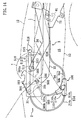
- said engaging pin 504 is provided to said rear connecting link 34, it moves between fully closed position corresponding to the roof panel 12 is fully closed (position shown in Fig. 9 ) and stored position corresponding to the roof panel 12 is stored (position shown in Figs. 14 ,15) while drawing an arc-shaped moving track T, together with the rear connecting link 34 rotating when the roof panel 12 performs opening/closing operation.
- a hook portion 501a in hook shape, and an inner periphery 501b of the hook portion 501a (see Figs. 10 , 11 ) engages with the engaging pin 504 when the roof panel 12 is in fully closed state.
- a contacting pin 505 contacting with a contacting bracket 33b provided to the front connecting link 33 when the roof panel 12 performs opening/closing operation so as to be brought into stored state, which will be explained in detail later.
- the hook member 501 thus composed is rotated in engagement direction by biasing force of the biasing spring 502 by releasing the driving of said first driving cable 503 (non-driving), and the hook portion 501a is caused to engage with the engaging pin 504 when the roof panel 12 is in fully closed state. Meanwhile, engagement of the hook portion 501a and the engaging pin 504 is disengaged by rotating the hook member 501 in disengaging direction against biasing force of the biasing spring 502 by driving of the first driving cable 503.
- the hook member 501 will be explained in detail hereafter.
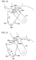
- the inner periphery 501 b of the hook portion 501a of said hook member 501 has such profile that, as shown in Fig. 10 , a forefront portion 501c is opened to outside of a circumference C3 with respect to the circumference C3 passing on the hook portion 501a about rotation center of the hook member 501 .
- the hook member 501 rotates in engagement direction by biasing force of the biasing spring 502.
- a stopper 506 contacting with the hook member 501 is provided so that hook member 501 stops at a stop position where an outer periphery 501d of the hook portion 501a is located on the movement track T of the engaging pin 504, and does not rotate further.
- the hook member 501 has inclined profile so that, when it stops at said stop position, the outer periphery 501d of the hook portion 501a is inclined with respect to the movement track T of the engaging pin 504 .
- forefront of the outer periphery 501d of the hook portion 501a is located outside the arc-shaped movement track T and is inclined with respect to the movement track T so that base end side thereof is located inside the arc-shaped movement track T .
- the engaging pin 504 moves relatively on the outer periphery 501d of the hook portion 501a from base end to forefront, and when a portion where engaging pin 504 contacts the hook portion 501a is shifted from the outer periphery 501d to the forefront portion 501c of the inner periphery, the hook member 501 starts rotation in engagement direction by biasing force of the biasing spring 502 and engages with the engaging pin 504 when the engaging pin 504 has moved to the fully closed position.
- the stored state locking mechanism 510 is provided to each of the roof panel opening/closing device 2 provided at both right and left and their configuration is identical, and therefore, explanation will be given for left side stored state locking mechanism 510.
- the stored state locking mechanism 510 is adapted to hold the roof panel 12 in the trunk room 15 when the roof panel 12 is stored, and includes, as shown in Fig. 9 , an engaging bar 511 mounted to a leading guide 512 provided to the base bracket 31 and is capable of directly moving in fore and aft directions, a biasing spring 513 for biasing the engaging bar 511 backward, a second driving cable 514 for moving the engaging bar 511 forward against biasing force of the biasing spring 513 , and a counter engaging member 516 (see Figs. 1 to 3 , 14 , 15) to which is formed a counter engaging hole 515 to which said engaging bar 511 is engaged.
- Said engaging bar 511 is provided so that forefront thereof protrudes in the trunk room 15 and at a position to be inserted to the counter engaging hole 515 of the counter engaging member 516 of the roof panel 12 in stored state (see Figs. 14 ,15).
- the engaging bar 511 is moved backward (inside of trunk room 15) by biasing force of the biasing spring 513 by releasing the driving of the second driving cable 514 (non-driving) to cause it to engage with the counter engaging hole 515 of the counter engaging member 516 of the roof panel 12 now in fully closed state.
- the engaging bar 511 is moved forward (outside of trunk room 15) against biasing force of the biasing spring 513 by driving the second driving cable 514 to release engagement of the engaging bar 511 and the counter engaging hole 515.
- Said link restricting mechanism 500 and the stored state locking mechanism 510 are driven by the electric motor 10 via a branched driving cable 100 .
- the branched driving cable 100 includes, as shown in Fig. 9 , an input cable 84 connected to said hook 81, the first driving cable 503 for driving said link restricting mechanism 500, the second driving cable 514 for driving said stored state locking mechanism 510, and a connecting member 110 for connecting the input cable 84, the first driving cable 503 and the second driving cable 514 .
- Said connecting member 110 is constituted by a fixing bracket 110a mounted to the vehicle body 1 and a connecting plate 110b rotatably provided to the fixing bracket 110a.
- Said input cable 84 is constituted by an outer cable 84a and an inner cable 84b slidably provided in the outer cable 84a .
- Input end of the outer cable 84a is provided to said base bracket 71 and input end of the inner cable 84b is provided to the hook 81.
- output end of the outer cable 84a is provided to said fixing bracket 110a and an output end of the inner cable 84b is attached to part of said connecting plate 110b away from the rotation center thereof by a predetermined third distance L3 .
- Said first driving cable 503 is constituted by an outer cable 503a and an inner cable 503b slidably provided in the outer cable 503a.
- Input end of the outer cable 503a is provided to the fixing bracket 110a and input end of the inner cable 503b is attached to part of said connecting plate 110b away from the rotation center thereof by a predetermined first distance L1 .
- output end of the outer cable 503a is provided to the base bracket 31 and at the same time, output end of the inner cable 503b is provided to hook member 501 .
- Said second driving cable 514 is constituted by an outer cable 514a and an inner cable 514b slidably provided in the outer cable 514a.
- Input end of the outer cable 514a is provided to the fixing bracket 110a and at the same time, input end of the inner cable 514b is attached to part of said connecting plate 110b away from the rotation center thereof by a predetermined second distance L2 .
- output end of the outer cable 514a is provided to the base bracket 31 and at the same time, output end of the inner cable 514b is provided to the engaging bar 511 .
- the inner cable 84b of said input cable 84 and the inner cable 514b of the second driving cable 514 are provided at the same position with respect to the connecting plate 110b , and therefore, the second distance L2 and the third distance L3 are identical.
- Said hook 81 is driven by the electric motor 10 via the lock transmitting link 83 (see Fig. 4 ). That is, the link restricting mechanism 500 and the stored state locking mechanism 510 being driven by the branched driving cable 100 whose input end is provided to the hook 81 are driven by the electric motor 10 .
- the hook 81 is in a state engaged with the engaging pin 82 and the hook member 501 is in a state engaged with the engaging pin 504.
- the engaging bar 511 is in a state being moved backward, it is not functioning as a locking mechanism since the roof panel 12 is in fully closed state.
- the inner cable 84b of the input cable 84 is being pulled in accordance with rotation of the hook 81 .
- the connecting plate 110b connected to output end thereof rotates in one direction (counterclockwise in Fig. 8 ), and when the connecting plate 110b rotates in one direction, the inner cable 503b of the first driving cable 503 and the inner cable 514b of the second driving cable 514 are pulled.
- the first driving cable 503 causes the hook member 501 to rotate in releasing direction, thereby releasing the engagement of the hook member 501 and the engaging pin 504.
- the stored state locking mechanism 510 does not function as the locking mechanism while the roof panel 12 is in closed state, the engaging bar 511 moves forward since the second driving cable 514 is pulled.
- stroke volume input to the input cable 84 (i.e., amount the inner cable 84b is pulled) is multiplied ( L1/L3 ) times and transmitted to the first driving cable 503, and multiplied ( L2/L3 ) times and transmitted to the second driving cable 514.
- the hook 81 remains being rotated in the direction of releasing the engagement with the engaging pin 82 , and therefore, the inner cable 84b of the input cable 84 remains in a state being pulled. Accordingly, the hook member 501 is held being rotated in the direction of releasing and at the same time, the engaging bar 511 is also held being moved forward.
- the roof panel 12 and the back window panel 13 are folded one above the other and are stored in the trunk room 15 .
- said transmitting mechanism 9 is brought into non-transmitting state
- the locking mechanism 8 performs locking operation to lock the trunk lid 14 . That is, the hook 81 rotates so as to be engaged with the engaging pin 82 . In this way, the pulling force acting on the inner cable 84b of the inner cable 84 is released and as a result, as shown in Fig. 15 , the hook member 501 rotates in engagement direction by biasing force of the biasing spring 502 and at the same time, the engaging bar 511 moves backward by biasing force of the biasing spring 513.
- the roof panel 12 is stored in the trunk room 15 , and the counter engaging hole 515 of said counter engaging member 516 provided to front edge portion of the roof panel 12 is located at a position opposed to the engaging bar 511 .
- the engaging bar 511 moves backward by biasing force of the biasing spring 13 , it engages with the counter engaging hole 515 to lock the roof panel 12 in stored state. That is, the stored state locking mechanism 510 functions as the locking mechanism.
- the link restricting mechanism 500 for holding the roof panel 12 in fully closed state does not need to function as the locking mechanism. Therefore, when the roof panel 12 performs opening/closing operation towards stored state, as shown in Figs. 14 , 15 , the hook member 501 is held at a position lower than the belt line BL formed on upper periphery of the vehicle body 1 and upper periphery of the trunk lid 14 by that the hook member 501 is rotated backward (i.e., releasing direction) together with the front connecting link 33 , while said contacting bracket 33b of the front connecting link 33 rotating backward contacts with the contacting pin 505 provided to the hook member 501 .
- the hook member 501 When the first driving cable 503 rotates to engagement position in non-driving state, the hook member 501 is in a state protruded above the belt line BL as shown in Fig. 8 . While the roof panel 12 is in fully closed state, the hook member 501 can not be viewed from outside the vehicle even if protruded upward from the belt line BL since it is hidden by the back window panel 13 . However, while the roof panel 12 is in stored state, since the back window panel 13 is stored in the trunk room 15 together with the roof panel 12 , if the hook member 501 is protruded above the belt line BL, it is viewed from outside the vehicle, thereby deteriorating beauty.
- the roof panel 12 while the roof panel 12 is in stored state, it is rotated to a position not protruding from the belt line BL, in releasing direction together with the front connecting link 33 rotating backwardly, to be held at a position hidden by the vehicle body 1 in the side elevation.
- the roof panel 12 is held in fully closed state by the stored state locking mechanism 510 and at the same time, the trunk lid 14 is also held in fully closed state by the locking mechanism 8 .
- the hook 81 remains being rotated in the direction of releasing the engagement with the engaging pin 82 , and therefore, the inner cable 84b of the input cable 84 remains in a state being pulled. Accordingly, the hook member 501 is held being rotated in the direction of releasing and at the same time, the engaging bar 511 is also held being moved forward.
- the trunk lid 14 is also in the fully closed state, and the locking mechanism 8 performs locking operation for the trunk lid 14 in fully closed state. That is, the hook 81 rotates so as to be engaged with the engaging pin 82 . The pulling force acting on the inner cable 84b of the input cable 84 is then released, and as a result, the hook member 501 rotates in engagement direction by biasing force of the biasing spring 502 and at the same time, the engaging bar 511 moves backward by biasing force of the biasing spring 513.
- the roof panel 12 is in fully closed state and the engaging pin 504 provided to the rear connecting link 34 is in fully closed position capable of engaging with the hook member 501. That is, when the hook member 501 rotates in engagement direction by biasing force of the biasing spring 502, the hook portion 501a engages with the engaging pin 504, thereby restricting the link mechanism 3 for the roof panel 12 in fully closed state.
- the link restricting mechanism 500 functions as the locking mechanism.
- the stored state locking mechanism 510 does not function as the locking mechanism while the engaging bar 511 simply moves backward.
- the roof panel 12 is held in fully closed state by the link restricting mechanism 500 and the trunk lid 14 is also held in fully closed sate by the locking mechanism 8 .
- the link restricting mechanism 500 and the stored state locking mechanism 510 can be driven by one input from the electric motor 10 via the hook 81 . That is, the link restricting mechanism 500 is a locking mechanism required while the roof panel 12 is in fully closed state and the stored state locking mechanism is a locking mechanism required while the roof panel 12 is in stored state, and since fully closed state and stored state of the roof panel 12 do not occur at the same time, the link restricting mechanism 500 and the stored state locking mechanism 510 may function as a locking mechanism alternatively. Therefore, while the roof panel 12 is in fully closed state, only the link restricting mechanism 500 should be taken into account and be operated by the electric motor 10.
- link restricting mechanism 500 and the stored state locking mechanism 510 can be driven by one branched driving cable 100 instead of driving them by two driving cables, respectively, the number of driving cables can be reduced and at the same time, ease of assembly can be improved through reduction in the number of cables.
- each of operation timings of the roof panel 12 and the trunk lid 14 can be set with flexible manner in such that opening/closing operation of the trunk lid 14 and opening/closing operation of the roof panel 12 are started with nearly same timing, instead of starting opening/closing operation having waited for unlocking of either component.
- time required for operation of the roof panel 12 or the like from fully closed state to stored state and from stored state to fully closed state can be shortened.
- connecting plate 110b of the connecting member 100 is configured to be rotatable, output end on the inner cable 84b of an input cable 84 , input end of the inner cable 503b of the first driving cable 503 and input end of the inner cable 514b of the second driving cable 514 are attached to the connecting plate 110b .
- Each of attached positions is located at a position away from rotation center of the connecting plate 110b by the first distance L1 , second distance L2 , and third distance L3, respectively.
- the pulling force input to the input cable 84 can be distributed to drive the first and second driving cables 503 and 514 , and the first driving cable 503 and the second driving cable 514 can be driven by increasing/decreasing stroke volume (amount of travel of the inner cable 84b as it is pulled).
- the first driving cable 503 and the second driving cable 514 can be driven while pulling force and stroke volume input to the input cable 84 are adjusted, by adjusting said first distance L1 , second distance L2 , and third distance L3 .
- the present invention is not limited thereto. That is, by connecting two means to be driven functioning simultaneously, or two means to be driven which should function alternatively to output end of each of the first driving cable 503 and the second driving cable 514 of the branched driving cable 100, two means to be driven can be driven by one driving source, thereby reducing the number of parts.
- the present invention is useful for a system for opening/closing a roof panel, which is supported by a vehicle body via a link mechanism, and which is capable of opening, closing, moving between a fully closed state where a vehicle cabin space is closed and a closed state where the vehicle cabin space is opened and is stored in a storage room at rear side of the vehicle, for holding the roof panel between the fully closed state and the stored state, and branched driving cable to be used for the system.
Landscapes
- Engineering & Computer Science (AREA)
- Mechanical Engineering (AREA)
- Power-Operated Mechanisms For Wings (AREA)
- Lock And Its Accessories (AREA)
- Superstructure Of Vehicle (AREA)
Abstract
Claims (3)
- Système pour ouvrir/fermer un panneau de toit, comprenant :un panneau de toit (12) supporté par une caisse de véhicule (1) par le biais d'un mécanisme de liaison (7) capable d'effectuer un mouvement d'ouverture/fermeture entre un état complètement fermé pour fermer un habitacle du véhicule (11) etun état rangé dans lequel l'habitacle du véhicule (11) est ouvert et ledit panneau de toit est rangé dans un compartiment de rangement (15) situé dans une partie arrière du véhicule ;un mécanisme de verrouillage d'état complètement fermé (500) pour retenir le panneau de toit (12) lorsque ledit panneau de toit (12) est dans un état complètement fermé ; etun mécanisme de verrouillage d'état rangé (510) pour retenir le panneau de toit (12) lorsque ledit panneau de toit (12) est dans un état rangé,ledit système comprenant en outre :un mécanisme d'entraînement (10) associé à un panneau de compartiment de rangement (14) prévu pour ouvrir et fermer ledit compartiment de rangement (15) ;un câble d'entraînement à branches (100) ayant un câble d'entrée (84) entraîné par ledit mécanisme d'entraînement (10) lorsqu'il est tiré, un organe de connexion (110) connecté à rotation à la caisse du véhicule (1), auquel est connectée l'extrémité de sortie du câble d'entrée (84), un premier câble de sortie (503), dont une extrémité d'entrée est connectée à l'organe de connexion (110) tandis qu'une extrémité de sortie de celui-ci est connectée audit mécanisme de verrouillage d'état complètement fermé (500), lequel premier câble de sortie (503) transmet une force de traction du câble d'entrée (84) au mécanisme de verrouillage d'état complètement fermé (500), et un deuxième câble de sortie, dont une extrémité d'entrée est connectée à l'organe de connexion tandis qu'une extrémité de sortie de celui-ci est connectée audit mécanisme de verrouillage d'état rangé (510), lequel deuxième câble de sortie (514) transmet une force de traction du câble d'entrée au mécanisme de verrouillage d'état rangé (510),ledit système étant caractérisé en ce que ledit mécanisme de verrouillage d'état complètement fermé (500) et ledit mécanisme de verrouillage d'état rangé (510) sont tous deux entraînés par ledit mécanisme d'entraînement au moyen dudit câble d'entraînement à branches (100).
- Système pour ouvrir/fermer le panneau de toit selon la revendication 1, caractérisé en ce que :ledit panneau de compartiment de rangement (14) est pourvu d'un mécanisme de verrouillage de panneau de compartiment de rangement pour retenir le panneau de compartiment de rangement (14) lorsque ledit compartiment de rangement (15) est fermé ;ledit mécanisme d'entraînement est prévu pour entraîner ledit mécanisme de verrouillage de panneau de compartiment de rangement ; ledit mécanisme de verrouillage d'état complètement fermé (500) et ledit mécanisme de verrouillage d'état rangé (510) étant entraînés de manière synchrone de telle sorte que ces deux mécanismes retiennent ledit panneau de toit (12) et ledit panneau de compartiment de rangement (14) lorsque ledit mécanisme de verrouillage de panneau de compartiment de rangement retient ledit panneau de compartiment de rangement (14) ; tandis que lesdits deux mécanismes libèrent ledit panneau de toit et ledit panneau de compartiment de rangement (14) lorsque ledit mécanisme de verrouillage de panneau de compartiment de rangement libère ledit panneau de compartiment de rangement (14).
- Système pour ouvrir/fermer le panneau de toit selon la revendication 1 ou 2, caractérisé en ce que :ledit premier câble de sortie (503) est connecté audit organe de connexion (110) en une position éloignée d'un centre de rotation dudit organe de connexion (110) sur une première distance prédéterminée ;ledit deuxième câble de sortie (514) est connecté audit organe de connexion (110) en une position éloignée du centre de rotation dudit organe de connexion (110) sur une deuxième distance prédéterminée ; etledit câble d'entrée (84) est connecté audit organe de connexion (110) en une position éloignée du centre de rotation dudit organe de connexion (110) sur une troisième distance prédéterminée.
Applications Claiming Priority (2)
| Application Number | Priority Date | Filing Date | Title |
|---|---|---|---|
| JP2006088854A JP4917820B2 (ja) | 2006-03-28 | 2006-03-28 | ルーフパネルの開閉システム |
| PCT/JP2007/056578 WO2007114138A1 (fr) | 2006-03-28 | 2007-03-28 | Système d'ouverture/fermeture pour panneau de toit et câble de commande séparé utilisé pour celui-ci |
Publications (3)
| Publication Number | Publication Date |
|---|---|
| EP2006140A1 EP2006140A1 (fr) | 2008-12-24 |
| EP2006140A4 EP2006140A4 (fr) | 2010-08-25 |
| EP2006140B1 true EP2006140B1 (fr) | 2011-05-11 |
Family
ID=38563407
Family Applications (1)
| Application Number | Title | Priority Date | Filing Date |
|---|---|---|---|
| EP20070740016 Ceased EP2006140B1 (fr) | 2006-03-28 | 2007-03-28 | Systeme d'ouverture/fermeture pour panneau de toit et cable de commande separe utilise pour celui-ci |
Country Status (4)
| Country | Link |
|---|---|
| US (1) | US8042424B2 (fr) |
| EP (1) | EP2006140B1 (fr) |
| JP (1) | JP4917820B2 (fr) |
| WO (1) | WO2007114138A1 (fr) |
Families Citing this family (6)
| Publication number | Priority date | Publication date | Assignee | Title |
|---|---|---|---|---|
| US8174146B2 (en) | 2009-04-16 | 2012-05-08 | Land Rover | Power split tailgate system and method |
| DE102012216427A1 (de) * | 2012-09-14 | 2014-05-15 | Magna Car Top Systems Gmbh | Kinematik für eine Klappe |
| DE102015000824A1 (de) * | 2014-01-23 | 2015-07-23 | Magna Closures Inc. | Türschlossvorrichtung für Kraftfahrzeuge |
| DE102015002053A1 (de) * | 2014-02-24 | 2015-08-27 | Magna Closures Inc. | Schloss für eine Tür eines Kraftfahrzeugs |
| US11465477B2 (en) | 2018-05-02 | 2022-10-11 | Abc Technologies Inc. | Tonneau cover |
| US11479095B2 (en) | 2018-05-02 | 2022-10-25 | Abc Technologies Inc. | Tonneau cover |
Family Cites Families (16)
| Publication number | Priority date | Publication date | Assignee | Title |
|---|---|---|---|---|
| US5694812A (en) * | 1995-04-28 | 1997-12-09 | United Technologies Automotive, Inc. | Multi-functional apparatus employing an electromagnetic device and an intermittent motion mechanism |
| JP3513690B2 (ja) * | 1997-05-26 | 2004-03-31 | 日信工業株式会社 | バーハンドル車両用ブレーキ装置 |
| US5927442A (en) * | 1997-06-02 | 1999-07-27 | Liao; Chi-Chao | Device for controlling the operational sequence of brake assemblies for bicycles |
| US5889341A (en) * | 1997-10-09 | 1999-03-30 | Ut Automotive Dearborn, Inc. | Multi-functional apparatus employing a linear wiper |
| DE10000639B4 (de) * | 2000-01-11 | 2005-05-04 | Siemens Ag | Betätigungsvorrichtung für Schiebetür |
| JP3649137B2 (ja) | 2001-03-13 | 2005-05-18 | アイシン精機株式会社 | リトラクタブルルーフの保持機構 |
| JP3636306B2 (ja) * | 2001-03-13 | 2005-04-06 | アイシン精機株式会社 | リトラクタブルルーフ |
| DE10116710C2 (de) | 2001-04-04 | 2003-03-13 | Edscha Cabrio Dachsys Gmbh | Verdeck für ein Cabriolet-Fahrzeug |
| JP4045810B2 (ja) * | 2002-02-12 | 2008-02-13 | マツダ株式会社 | 車両の上部車体構造 |
| DE10216417B4 (de) * | 2002-04-12 | 2004-06-17 | Cts Fahrzeug-Dachsysteme Gmbh | Zwischen einer Schließposition und einer Ablageposition verstellbares Fahrzeugdach |
| DE10252987B4 (de) * | 2002-11-14 | 2005-03-17 | Wilhelm Karmann Gmbh | Cabriolet-Fahrzeug mit versenkbarem Verdeck |
| JP4071167B2 (ja) * | 2003-06-30 | 2008-04-02 | 本田技研工業株式会社 | 車両用シートの電動収納構造 |
| JP4405312B2 (ja) * | 2004-04-27 | 2010-01-27 | 株式会社ホンダロック | スライドドアのロック装置 |
| US7562917B2 (en) * | 2006-01-10 | 2009-07-21 | Ford Global Technologies, Llc | Door latch system for automotive vehicle |
| JP4755528B2 (ja) * | 2006-05-17 | 2011-08-24 | 三井金属アクト株式会社 | 車両用ドアラッチのリモートコントロール装置 |
| JP4759443B2 (ja) * | 2006-05-31 | 2011-08-31 | 三井金属アクト株式会社 | 車両用ドアラッチのリモートコントロール装置 |
-
2006
- 2006-03-28 JP JP2006088854A patent/JP4917820B2/ja not_active Expired - Fee Related
-
2007
- 2007-03-28 EP EP20070740016 patent/EP2006140B1/fr not_active Ceased
- 2007-03-28 WO PCT/JP2007/056578 patent/WO2007114138A1/fr not_active Ceased
- 2007-03-28 US US12/295,159 patent/US8042424B2/en active Active
Also Published As
| Publication number | Publication date |
|---|---|
| JP4917820B2 (ja) | 2012-04-18 |
| EP2006140A4 (fr) | 2010-08-25 |
| JP2007261420A (ja) | 2007-10-11 |
| US20100007178A1 (en) | 2010-01-14 |
| EP2006140A1 (fr) | 2008-12-24 |
| US8042424B2 (en) | 2011-10-25 |
| WO2007114138A1 (fr) | 2007-10-11 |
Similar Documents
| Publication | Publication Date | Title |
|---|---|---|
| EP2006140B1 (fr) | Systeme d'ouverture/fermeture pour panneau de toit et cable de commande separe utilise pour celui-ci | |
| EP3617433B1 (fr) | Ensemble poignée de portière externe rétractable pour véhicule | |
| US9631404B2 (en) | Vehicle door lock apparatus | |
| US10808433B2 (en) | Tailgate opening and closing device for vehicle | |
| US7125063B2 (en) | Lid mechanism and center console box | |
| US20180171677A1 (en) | Tailgate opening and closing device for vehicle | |
| KR20190028966A (ko) | 순서에 상관없이 개폐가능한 차량의 대향식 스윙도어 | |
| US20070158973A1 (en) | Tailgate assembly | |
| US6131337A (en) | Vehicle door closing apparatus | |
| WO2013047377A1 (fr) | Dispositif de poignée de porte pour véhicule | |
| EP2090729A2 (fr) | Système de verrouillage de porte | |
| EP2006137B1 (fr) | Dispositif d'ouverture/fermeture pour panneau de toit | |
| WO2007114161A1 (fr) | Système de toit escamotable pour automobiles | |
| JP4833710B2 (ja) | パネル部材の開閉装置 | |
| JP7018861B2 (ja) | スライドドア付き車両 | |
| JP2009132203A (ja) | ルーフ開閉装置 | |
| JPH0268220A (ja) | 自動車のキャンバストップ | |
| JP4026459B2 (ja) | スライドドアのハンドル装置 | |
| US7267397B2 (en) | Open roof construction for a vehicle | |
| JP2003220833A (ja) | 車両用ルーフ開閉装置 | |
| JP2013076217A (ja) | 車両用ドアハンドル装置 | |
| EP1614570A2 (fr) | Toit ouvrant de véhicule | |
| JP2000103240A (ja) | ラゲージのヒンジ機構 | |
| JP2013076218A (ja) | 車両用ドアハンドル装置 | |
| JP2006347524A (ja) | ラッゲージパネルの開閉装置 |
Legal Events
| Date | Code | Title | Description |
|---|---|---|---|
| PUAI | Public reference made under article 153(3) epc to a published international application that has entered the european phase |
Free format text: ORIGINAL CODE: 0009012 |
|
| 17P | Request for examination filed |
Effective date: 20081027 |
|
| AK | Designated contracting states |
Kind code of ref document: A1 Designated state(s): DE FR GB IT |
|
| DAX | Request for extension of the european patent (deleted) | ||
| RBV | Designated contracting states (corrected) |
Designated state(s): DE FR GB IT |
|
| A4 | Supplementary search report drawn up and despatched |
Effective date: 20100728 |
|
| GRAP | Despatch of communication of intention to grant a patent |
Free format text: ORIGINAL CODE: EPIDOSNIGR1 |
|
| RIC1 | Information provided on ipc code assigned before grant |
Ipc: E05F 15/10 20060101ALI20101026BHEP Ipc: E05B 65/12 20060101ALI20101026BHEP Ipc: B60J 7/20 20060101ALI20101026BHEP Ipc: B60J 7/12 20060101ALI20101026BHEP Ipc: B60J 7/185 20060101AFI20101026BHEP |
|
| GRAS | Grant fee paid |
Free format text: ORIGINAL CODE: EPIDOSNIGR3 |
|
| GRAA | (expected) grant |
Free format text: ORIGINAL CODE: 0009210 |
|
| AK | Designated contracting states |
Kind code of ref document: B1 Designated state(s): DE FR GB IT |
|
| REG | Reference to a national code |
Ref country code: GB Ref legal event code: FG4D |
|
| REG | Reference to a national code |
Ref country code: DE Ref legal event code: R096 Ref document number: 602007014505 Country of ref document: DE Effective date: 20110622 |
|
| PLBE | No opposition filed within time limit |
Free format text: ORIGINAL CODE: 0009261 |
|
| STAA | Information on the status of an ep patent application or granted ep patent |
Free format text: STATUS: NO OPPOSITION FILED WITHIN TIME LIMIT |
|
| 26N | No opposition filed |
Effective date: 20120214 |
|
| REG | Reference to a national code |
Ref country code: DE Ref legal event code: R097 Ref document number: 602007014505 Country of ref document: DE Effective date: 20120214 |
|
| REG | Reference to a national code |
Ref country code: FR Ref legal event code: PLFP Year of fee payment: 10 |
|
| REG | Reference to a national code |
Ref country code: FR Ref legal event code: PLFP Year of fee payment: 11 |
|
| REG | Reference to a national code |
Ref country code: FR Ref legal event code: PLFP Year of fee payment: 12 |
|
| PGFP | Annual fee paid to national office [announced via postgrant information from national office to epo] |
Ref country code: GB Payment date: 20200325 Year of fee payment: 14 Ref country code: IT Payment date: 20200325 Year of fee payment: 14 |
|
| PGFP | Annual fee paid to national office [announced via postgrant information from national office to epo] |
Ref country code: FR Payment date: 20200324 Year of fee payment: 14 |
|
| GBPC | Gb: european patent ceased through non-payment of renewal fee |
Effective date: 20210328 |
|
| PG25 | Lapsed in a contracting state [announced via postgrant information from national office to epo] |
Ref country code: FR Free format text: LAPSE BECAUSE OF NON-PAYMENT OF DUE FEES Effective date: 20210331 Ref country code: GB Free format text: LAPSE BECAUSE OF NON-PAYMENT OF DUE FEES Effective date: 20210328 |
|
| PG25 | Lapsed in a contracting state [announced via postgrant information from national office to epo] |
Ref country code: IT Free format text: LAPSE BECAUSE OF NON-PAYMENT OF DUE FEES Effective date: 20210328 |
|
| PGFP | Annual fee paid to national office [announced via postgrant information from national office to epo] |
Ref country code: DE Payment date: 20230320 Year of fee payment: 17 |
|
| REG | Reference to a national code |
Ref country code: DE Ref legal event code: R119 Ref document number: 602007014505 Country of ref document: DE |
|
| PG25 | Lapsed in a contracting state [announced via postgrant information from national office to epo] |
Ref country code: DE Free format text: LAPSE BECAUSE OF NON-PAYMENT OF DUE FEES Effective date: 20241001 |
|
| PG25 | Lapsed in a contracting state [announced via postgrant information from national office to epo] |
Ref country code: DE Free format text: LAPSE BECAUSE OF NON-PAYMENT OF DUE FEES Effective date: 20241001 |