EP2006157B1 - Rétroviseur d'un véhicule - Google Patents
Rétroviseur d'un véhicule Download PDFInfo
- Publication number
- EP2006157B1 EP2006157B1 EP08016972A EP08016972A EP2006157B1 EP 2006157 B1 EP2006157 B1 EP 2006157B1 EP 08016972 A EP08016972 A EP 08016972A EP 08016972 A EP08016972 A EP 08016972A EP 2006157 B1 EP2006157 B1 EP 2006157B1
- Authority
- EP
- European Patent Office
- Prior art keywords
- light
- emitting means
- light emitting
- mirror according
- exterior mirror
- Prior art date
- Legal status (The legal status is an assumption and is not a legal conclusion. Google has not performed a legal analysis and makes no representation as to the accuracy of the status listed.)
- Active
Links
Images
Classifications
-
- B—PERFORMING OPERATIONS; TRANSPORTING
- B60—VEHICLES IN GENERAL
- B60R—VEHICLES, VEHICLE FITTINGS, OR VEHICLE PARTS, NOT OTHERWISE PROVIDED FOR
- B60R1/00—Optical viewing arrangements; Real-time viewing arrangements for drivers or passengers using optical image capturing systems, e.g. cameras or video systems specially adapted for use in or on vehicles
- B60R1/12—Mirror assemblies combined with other articles, e.g. clocks
- B60R1/1207—Mirror assemblies combined with other articles, e.g. clocks with lamps; with turn indicators
-
- B—PERFORMING OPERATIONS; TRANSPORTING
- B60—VEHICLES IN GENERAL
- B60Q—ARRANGEMENT OF SIGNALLING OR LIGHTING DEVICES, THE MOUNTING OR SUPPORTING THEREOF OR CIRCUITS THEREFOR, FOR VEHICLES IN GENERAL
- B60Q1/00—Arrangement of optical signalling or lighting devices, the mounting or supporting thereof or circuits therefor
- B60Q1/26—Arrangement of optical signalling or lighting devices, the mounting or supporting thereof or circuits therefor the devices being primarily intended to indicate the vehicle, or parts thereof, or to give signals, to other traffic
- B60Q1/2661—Arrangement of optical signalling or lighting devices, the mounting or supporting thereof or circuits therefor the devices being primarily intended to indicate the vehicle, or parts thereof, or to give signals, to other traffic mounted on parts having other functions
- B60Q1/2665—Arrangement of optical signalling or lighting devices, the mounting or supporting thereof or circuits therefor the devices being primarily intended to indicate the vehicle, or parts thereof, or to give signals, to other traffic mounted on parts having other functions on rear-view mirrors
Definitions
- the invention relates to an exterior mirror of a vehicle according to the preamble of claim 1.
- Exterior mirrors in which a light function is integrated in the form of a turn signal, are known.
- a turn signal module is integrated in a forward-facing rear wall of the mirror housing.
- various components such as an actuator for tilting the mirror, are arranged for a possible heating device or for folding the exterior mirror into a parking position.
- an exterior mirror of a vehicle which has light emitting diodes with different light functions mounted in a module in its front-facing housing part.
- laterally emitting LEDs are provided which are operated as flashing lights and on the main surface transverse to LEDs that emit forward and can be operated as a daytime running light.
- the object of the invention is to provide an exterior mirror of a vehicle whose scope is extended despite limited space.
- the exterior mirror according to the invention of a vehicle has a mounted in the rearward opening in a housing with a
- Cavity in which a mirror is receivable, and a forward facing, the cavity bounding the rear wall with an outer surface.
- At least two different light functions can be displayed on the outer surface and / or on the mirror, the light functions comprising light sources that are combined within the housing in one or more, in particular a few, preferably at most two, modules.
- the light functions are integrated via the module or modules with different signal functions, which are installed in the exterior mirror.
- each module is assigned at least one light function or signal function.
- the lighting means are arranged in a module-forming insert, which is embedded in the rear wall of the exterior mirror.
- the light sources are arranged for different light functions in a common module, wherein first light bulbs protrude into apertures within forwardly open reflectors and are surrounded in a coronary manner by a plurality of second light bulbs.
- the bulbs emit different colored light.
- the light functions are at least two of the group flashing light, daytime running light, side marker light (SML), parking light, position light (PO light), limiting light, ambient light, blind spot monitoring light (SWA).
- the blind spot monitoring light preferably backlit a display, which the driver can see in the mirror glass, while the other light functions are preferably arranged in the region of the rear wall, which is not directly visible by the driver, and their lights light down, forward, to the side and / or radiate upwards.
- the insert can be made extremely compact.
- a module comprises one or more carriers for the one or more lighting means, power supply means, fastening means for attachment in the housing and electronics for controlling the one or more bulbs.
- the bulbs can light through corresponding openings in the housing to the outside or they are inserted into a housing forming a module insert.
- the module or modules are arranged on the inside on the rear wall.
- the module for applying the various light functions on electrical elements which are divided over a few boards in the cavity, for example, on one or two boards. A suitable number will be selected by the person skilled in the art as needed. This assembly is possible even with little space available.
- a transparent lens it may be provided on the insert a transparent lens, so that they are readily used in the exterior mirror and a separate seal can be avoided. Alternatively, however, for example, a separate cover or the like may be provided.
- At least one rearwardly directed depression can be introduced in the rear wall, which has an opening for a luminous means which points outward from the cavity.
- the at least one depression may be oval and / or a depression may be round.
- the at least one recess serves as a reflector of the lighting means. If LEDs (light-emitting diodes) are used as light sources, the indentation can at least partially reflect the radiated light in such a way that some alignment of the radiated light takes place. For example, if the light function is a daytime running light, a preceding vehicle can better recognize the following vehicle, which enhances road safety.
- LEDs light-emitting diodes
- the oval depression can be arranged approximately horizontally, the illumination means being arranged in the region of a mirror-like edge and the depression extending away from the edge.
- the recess can be formed so deep that a lateral visibility of the light function is given.
- each light source can be provided with a sealing seal to the outside. This can prevent the penetration of dirt or moisture in the exterior mirror.
- the seal is expediently arranged as a clear layer over the light sources, for example as a coating poured over it.
- the seal is placed as a cover on the housing.
- the cover may extend over the entire rear wall, or the cover may be limited to an area with the one or more depressions and / or the insert.
- the lighting means can be provided so that different colors can be displayed.
- the blind spot monitoring light may output a color depending on a distance to an obstacle. This can be done by means known to those skilled in the art, such as filter elements or different colored bulbs that can be activated accordingly.
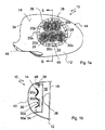
- FIGS. 1a and 1b an embodiment of a preferred exterior mirror 10 is shown, wherein FIG. 1a a top view and FIG. 1b shows a section along the line bb ..
- the exterior mirror 10 is arranged with a vehicle-side projection 46, which is only indicated in the figure, on a body of a vehicle.
- the outer mirror 10 comprises a housing 12 having a cavity 16 and with a rearwardly directed in the assembled state opening 36, in a Mirror 18 is used with a servomotor 38 for tilting the mirror 18.
- the cavity 16 is bounded in the forward direction by a forwardly curved rear wall 34 having an outer surface 14.
- the bulbs 26, 28 are combined in a module 48, which is embedded in the rear wall 34.
- the rear wall 34 on an opening 30a.
- the five lighting means 26 protrude into apertures 32a within forwardly open reflectors 30b and are surrounded by a plurality of lighting means 28, of which only a few are indicated for the sake of clarity.
- the bulbs 28 also sit in small, unspecified reflectors The bulbs 26 and 28 give different colored light.
- the trained as an insert module 48 is covered with a seal designed as a transparent cover 40 and protected against ingress of dirt and moisture.
- the seal 40 may be part of the module 48, or it may be provided over the entire rear wall 34 as in the next embodiment, a corresponding cover.
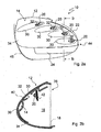
- FIGS. 2a and 2b illustrate an embodiment of an exterior mirror 10 according to the invention of a vehicle in a plan view of a rear wall 34 (FIG. FIG. 2a ) and as a section along the line bb ( FIG. 2b ), in addition to the in Fig. 1a and 1b is provided, wherein the in Fig. 1 a, 1 b pictured insert is not shown.
- the exterior mirror 10 is arranged with a vehicle-side projection 46, which is only indicated in the figure, on a body of a vehicle.
- the outer mirror 10 comprises a housing 12 with a cavity 16 and with a rearwardly directed in the assembled state opening 36, in which a mirror 18 is inserted.
- the cavity 16 is bounded in the forward direction by a forwardly curved rear wall 34 having an outer surface 14.
- the bulbs 20, 22, 24 are combined in a schematically indicated module 42, which is fastened on the inside to the rear wall 34.
- the luminous means 22 can be associated, for example, with a position light and illuminant 24 with an ambient light radiating downwards, while the illuminants 20, which are preferably designed as LEDs, can be used as flashing light.
- the four light sources 20 are introduced into four recesses 30 directed backwards and protrude out of the cavity 16 through an opening 32 in the rear wall 34 of the housing 12 to the outside.
- the oval-shaped recesses 30 extend approximately horizontally, wherein the bulbs 20 are arranged in the region of a mirror-like edge 44 of the housing 12 and the recess 30 extends away from the edge 44 away.
- the recesses 30 serve as a kind of reflector of the luminous means 20 and allow by an at least low directivity of the light, a detection of the bulbs 20 from the front and from the side.
- the recess 30 may be formed so deep that a lateral visibility of the light function is given.
- the bulbs 20, and also 22 and 24, are provided with an outwardly sealing seal 40, which is placed as a transparent cover on the rear wall 34 of the exterior mirror 10.
- the cover 40 formed as a seal 40 also allows a light output down. Due to the smooth and all-over shape of the seal 40, the interior of the exterior mirror 10 is protected from contamination or the ingress of moisture, and the seal 40 can be easily cleaned from the outside.
Landscapes
- Engineering & Computer Science (AREA)
- Mechanical Engineering (AREA)
- Multimedia (AREA)
- Lighting Device Outwards From Vehicle And Optical Signal (AREA)
- Rear-View Mirror Devices That Are Mounted On The Exterior Of The Vehicle (AREA)
Claims (14)
- Rétroviseur extérieur d'un véhicule ayant une ouverture (36) orientée vers l'arrière à l'état monté dans un logement (12) ayant un espace creux (16), dans lequel un miroir (18) peut être logé, ainsi qu'une paroi arrière (34) orientée vers l'avant, délimitant l'espace creux (16) avec une surface extérieure (14), de sorte qu'au moins deux fonctions lumineuses différentes peuvent être représentées sur la surface extérieure (14) et/ou sur le miroir (18), les fonctions lumineuses comprenant des moyens lumineux (20, 22, 24, 26, 28) qui sont réunis au sein du logement (12) en un ou plusieurs modules (42, 48), caractérisé en ce que
les moyens lumineux (26, 28) sont disposés dans un insert formant un des modules (48), qui est introduit dans la paroi arrière (34),
un ou plusieurs modules (48) sont agencés derrière un scellement transparent (40), qui est installé en tant que capot du logement (12),
les moyens lumineux (26, 28) pour des fonctions lumineuses différentes sont installés dans un module commun (48), de sorte que des premiers moyens lumineux (26), à l'intérieur de percements (32a), sont entourés sur le dessus par des réflecteurs (30b) ouverts vers l'avant, et en bordure par plusieurs deuxièmes moyens lumineux (28), de sorte que les premiers et deuxièmes moyens lumineux (26, 28) fournissent des lumières d'une couleur différente, et de sorte que
les fonctions lumineuses sont au moins deux parmi le groupe que sont le feu clignotant, le feu diurne, le feu de marquage latéral, le feu de veille, le feu de position, le feu de délimitation, le feu de champ périphérique, le feu de surveillance de l'angle mort. - Rétroviseur extérieur selon la revendication 1, caractérisé en ce que les deuxièmes moyens lumineux (28) sont placés dans de petits réflecteurs.
- Rétroviseur extérieur selon la revendication 1, caractérisé en ce que le ou les modules (42, 48) présentent un module de commande lumineuse commun dans le logement (12).
- Rétroviseur extérieur selon la revendication 1 ou 2, caractérisé en ce que le ou les modules (42, 48) sont disposés du côté interne sur la paroi arrière (34).
- Rétroviseur extérieur selon l'une quelconque des revendications précédentes, caractérisé en ce que le ou les modules (42, 48) présentent des éléments électriques pour solliciter les différentes fonctions lumineuses, qui sont répartis sur quelques disques dans l'espace creux (32).
- Rétroviseur extérieur selon l'une quelconque des revendications précédentes, caractérisé en ce qu'au moins un renfoncement (30) orienté vers l'arrière est réalisé dans la paroi arrière (34), lequel présente un percement (36) pour un moyen lumineux (20, 26, 28), qui est tourné vers l'extérieur depuis l'espace creux (16).
- Rétroviseur extérieur selon la revendication 6, caractérisé en ce que le au moins un renfoncement (30) est réalisé de forme ovale
- Rétroviseur extérieur selon la revendication 6 ou 7, caractérisé en ce que le au moins un renfoncement (30) est réalisé de forme ronde.
- Rétroviseur extérieur selon l'une quelconque des revendications 6 à 8, caractérisé en ce que le au moins un renfoncement (30) sert de réflecteur du moyen lumineux (20).
- Rétroviseur extérieur selon l'une quelconque des revendications 6 à 9, caractérisé en ce que le renfoncement ovale (30) est disposé de manière approximativement horizontale, le moyen lumineux (20) étant disposé dans la région d'un bord proche du miroir (44), et le renfoncement (30) s'étendant à l'écart du bord (44).
- Rétroviseur extérieur selon l'une quelconque des revendications précédentes, caractérisé en ce que le renfoncement (30) est réalisé de manière si profonde qu'une perceptibilité latérale de la fonction lumineuse en résulte.
- Rétroviseur extérieur selon l'une quelconque des revendications précédentes, caractérisé en ce que chaque moyen lumineux (20, 22, 24, 26, 28) est pourvu d'un scellement (40) fournissant une étanchéité vis-à-vis de l'extérieur.
- Rétroviseur extérieur selon la revendication 12, caractérisé en ce que le scellement (40) est disposé en tant que couche transparente au-dessus des moyens lumineux (20, 22, 24, 26, 28).
- Rétroviseur extérieur selon l'une quelconque des revendications précédentes, caractérisé en ce que les moyens lumineux (20, 22, 24, 26, 28) sont prévus de sorte que différentes couleurs peuvent être représentées.
Applications Claiming Priority (2)
| Application Number | Priority Date | Filing Date | Title |
|---|---|---|---|
| DE102006025070A DE102006025070A1 (de) | 2006-05-23 | 2006-05-23 | Außenspiegel eines Fahrzeugs |
| EP07009920A EP1859995B1 (fr) | 2006-05-23 | 2007-05-18 | Rétroviseur d'un véhicule |
Related Parent Applications (2)
| Application Number | Title | Priority Date | Filing Date |
|---|---|---|---|
| EP07009920A Division EP1859995B1 (fr) | 2006-05-23 | 2007-05-18 | Rétroviseur d'un véhicule |
| EP07009920.5 Division | 2007-05-18 |
Publications (2)
| Publication Number | Publication Date |
|---|---|
| EP2006157A1 EP2006157A1 (fr) | 2008-12-24 |
| EP2006157B1 true EP2006157B1 (fr) | 2013-02-20 |
Family
ID=38328547
Family Applications (2)
| Application Number | Title | Priority Date | Filing Date |
|---|---|---|---|
| EP07009920A Active EP1859995B1 (fr) | 2006-05-23 | 2007-05-18 | Rétroviseur d'un véhicule |
| EP08016972A Active EP2006157B1 (fr) | 2006-05-23 | 2007-05-18 | Rétroviseur d'un véhicule |
Family Applications Before (1)
| Application Number | Title | Priority Date | Filing Date |
|---|---|---|---|
| EP07009920A Active EP1859995B1 (fr) | 2006-05-23 | 2007-05-18 | Rétroviseur d'un véhicule |
Country Status (3)
| Country | Link |
|---|---|
| US (1) | US7594742B2 (fr) |
| EP (2) | EP1859995B1 (fr) |
| DE (2) | DE102006025070A1 (fr) |
Families Citing this family (7)
| Publication number | Priority date | Publication date | Assignee | Title |
|---|---|---|---|---|
| DE102007010747A1 (de) * | 2007-02-27 | 2008-08-28 | Schefenacker Patents S.à.r.l. | Außenrückblickspiegel für Fahrzeuge, insbesondere Kraftfahrzeuge |
| GB2466428B (en) * | 2008-12-16 | 2013-03-27 | James Akira Matsumiya | Viewing apparatus for a vehicle |
| JP5264615B2 (ja) | 2009-01-29 | 2013-08-14 | 本田技研工業株式会社 | 車両用灯火装置 |
| FR2943288B1 (fr) * | 2009-03-20 | 2013-02-08 | Valeo Vision Sas | Dispositif optique pour vehicule automobile. |
| JP5189559B2 (ja) | 2009-05-28 | 2013-04-24 | 株式会社村上開明堂 | ターンランプユニット |
| US10576896B2 (en) | 2010-10-01 | 2020-03-03 | Magna Mirrors Of America, Inc. | Vehicle exterior mirror system with light module |
| DE102025110272A1 (de) | 2025-03-18 | 2026-04-02 | Audi Aktiengesellschaft | Außenspiegel für ein Fahrzeug |
Family Cites Families (23)
| Publication number | Priority date | Publication date | Assignee | Title |
|---|---|---|---|---|
| US4049891A (en) | 1976-06-21 | 1977-09-20 | Massachusetts Institute Of Technology | Compositions for fast alkali-metal-ion transport |
| GB1591234A (en) | 1976-11-12 | 1981-06-17 | Texas Instruments Inc | Solid dry electrochromic display |
| US4297005A (en) | 1979-06-25 | 1981-10-27 | Bell Telephone Laboratories, Incorporated | Persistent memory cell |
| US4258984A (en) | 1979-09-14 | 1981-03-31 | Bell Telephone Laboratories, Incorporated | Iridium oxide based electrochromic devices |
| DE3016524A1 (de) | 1980-04-29 | 1981-11-05 | Max-Planck-Gesellschaft zur Förderung der Wissenschaften e.V., 3400 Göttingen | Verfahren zu seiner herstellung und seine verwendung |
| DE3207131A1 (de) | 1982-02-27 | 1983-09-08 | Rosenthal Technik Ag, 8672 Selb | Keramiksubstrat als traeger fuer elektronische bauelemente und integrierte elektronische schaltkreise |
| US6441943B1 (en) * | 1997-04-02 | 2002-08-27 | Gentex Corporation | Indicators and illuminators using a semiconductor radiation emitter package |
| CA2230930A1 (fr) * | 1997-04-25 | 1998-10-25 | Dale Gathergood | Retroviseur exterieur avec clignotant integre |
| US6152590A (en) * | 1998-02-13 | 2000-11-28 | Donnelly Hohe Gmbh & Co. Kg | Lighting device for motor vehicles |
| DE29804489U1 (de) * | 1998-03-13 | 1998-05-20 | Reitter & Schefenacker GmbH & Co. KG, 73730 Esslingen | Außenrückblickspiegel für Fahrzeuge, vorzugsweise für Kraftfahrzeuge |
| DE19951178A1 (de) * | 1999-05-25 | 2000-12-21 | Choe Byung Ju | Außenrückblickspiegel für ein Fahrzeug |
| US6049271A (en) * | 1999-06-29 | 2000-04-11 | Chu; Ching-Ti | Vehicle rearview mirror with multiple signal means |
| DE20001407U1 (de) * | 2000-01-27 | 2000-03-16 | Reitter & Schefenacker GmbH & Co. KG, 73730 Esslingen | Außenrückblickspiegel für Fahrzeuge, vorzugsweise für Kraftfahrzeuge |
| DE20008994U1 (de) * | 2000-05-18 | 2000-08-24 | Lutzenberger, Helmut, 87534 Oberstaufen | Außenrückspiegel |
| DE10025810B4 (de) * | 2000-05-24 | 2014-01-23 | SMR Patents S.à.r.l. | Leuchteneinheit, insbesondere für Außenrückblickspiegel von Fahrzeugen, vorzugsweise von Kraftfahrzeugen |
| DE20011341U1 (de) * | 2000-06-28 | 2000-09-21 | FER Fahrzeugelektrik GmbH, 99817 Eisenach | Leuchtenbaugruppe |
| ES2278670T3 (es) * | 2000-10-04 | 2007-08-16 | Fer Fahrzeugelektrik Gmbh | Luz intermitente lateral. |
| US6769798B2 (en) * | 2002-04-11 | 2004-08-03 | E'sam Co.,. Ltd. | Side mirror cover and cover lamp to be used therefor |
| US6918685B2 (en) * | 2002-04-15 | 2005-07-19 | K. W. Muth Company, Inc. | Mirror with integrated signaling assembly |
| DE10251380A1 (de) * | 2002-11-01 | 2004-05-13 | Volkswagen Ag | Außenspiegel mit optischem Signalgeber |
| JP4086227B2 (ja) | 2002-12-09 | 2008-05-14 | 本田技研工業株式会社 | バックミラー装置 |
| US6880960B2 (en) | 2003-03-26 | 2005-04-19 | E'sam Co., Ltd. | Side mirror cover and side mirror body |
| US6932497B1 (en) * | 2003-12-17 | 2005-08-23 | Jean-San Huang | Signal light and rear-view mirror arrangement |
-
2006
- 2006-05-23 DE DE102006025070A patent/DE102006025070A1/de not_active Ceased
-
2007
- 2007-05-18 EP EP07009920A patent/EP1859995B1/fr active Active
- 2007-05-18 DE DE502007005314T patent/DE502007005314D1/de active Active
- 2007-05-18 EP EP08016972A patent/EP2006157B1/fr active Active
- 2007-05-23 US US11/752,767 patent/US7594742B2/en active Active
Also Published As
| Publication number | Publication date |
|---|---|
| DE102006025070A1 (de) | 2007-11-29 |
| EP1859995A3 (fr) | 2008-04-09 |
| US7594742B2 (en) | 2009-09-29 |
| EP1859995B1 (fr) | 2010-10-13 |
| US20080084703A1 (en) | 2008-04-10 |
| DE502007005314D1 (de) | 2010-11-25 |
| EP1859995A2 (fr) | 2007-11-28 |
| EP2006157A1 (fr) | 2008-12-24 |
Similar Documents
| Publication | Publication Date | Title |
|---|---|---|
| DE102012003200B4 (de) | Lichtdurchlässiges Karosserieteil der Außenhaut eines Kraftfahrzeugs | |
| EP3825601B1 (fr) | Élément lumineux pour un véhicule automobile et véhicule automobile | |
| EP2006157B1 (fr) | Rétroviseur d'un véhicule | |
| EP1914118A2 (fr) | Miroir extérieur avec moyen lumineux | |
| DE102007015703A1 (de) | Kraftfahrzeug | |
| DE112018002995T5 (de) | Fahrzeugaussensystem mit lichtmodul | |
| DE102004048669B4 (de) | Fahrzeugseitenspiegelgerät | |
| EP1215081A2 (fr) | Feu pour véhicule | |
| WO2005018987A1 (fr) | Dispositif d'eclairage de vehicules | |
| DE102012211822A1 (de) | Gehäuseschale für eine Leuchteneinheit eines Kraftfahrzeug und Verfahren zum Herstellen einer Gehäuseschale für eine Leuchteneinheit eines Kraftfahrzeug | |
| DE202016103822U1 (de) | Kraftfahrzeug mit A-Säulen umfassend Fahrtrichtungsanzeigevorrichtungen | |
| DE10337615B3 (de) | Leuchtvorrichtung für Fahrzeuge | |
| DE102009025637B4 (de) | Versenkt angeordnetes, beleuchtetes, hochgesetzt und mittig montiertes Bremslicht (CHMSL) | |
| WO2005100089A1 (fr) | Retroviseur exterieur pour vehicules, notamment pour vehicules a moteur | |
| DE102012211821A1 (de) | Leuchteneinheit für ein Kraftfahrzeug und Verfahren zum Herstellen eines Gehäuseelementes einer Leuchteneinheit für ein Kraftfahrzeug | |
| EP3792111B1 (fr) | Luminaire | |
| DE102021201145A1 (de) | Kraftfahrzeugscheinwerfer und Verfahren zum Betrieb eines Kraftfahrzeugscheinwerfers | |
| DE10341572B4 (de) | Fahrzeugleuchte mit Elektrolumineszenz-Anordnung | |
| DE102010045145A1 (de) | Beleuchtungsvorrichtung für Fahrzeuge | |
| EP1775512A1 (fr) | Dispositif d'allumage pour véhicules, de préférence feu arrière pour véhicule automoteur | |
| EP4067732A1 (fr) | Lampe pour véhicule dotée d'une surface d'éclairage comprenant une surface de réflecteur | |
| DE102020116264A1 (de) | Lichtleitervorrichtung, fahrzeugkomponente und fahrzeug | |
| DE102020204906A1 (de) | Heckklappe eines Fahrzeugs mit einer Beleuchtungsanordnung an einteiligem Außenblech | |
| DE102015108486A1 (de) | Seitenblinkleuchte für Fahrzeuge | |
| DE102006032023B4 (de) | Vorrichtung zum Beleuchten eines Kraftfahrzeuges |
Legal Events
| Date | Code | Title | Description |
|---|---|---|---|
| PUAI | Public reference made under article 153(3) epc to a published international application that has entered the european phase |
Free format text: ORIGINAL CODE: 0009012 |
|
| AC | Divisional application: reference to earlier application |
Ref document number: 1859995 Country of ref document: EP Kind code of ref document: P |
|
| AK | Designated contracting states |
Kind code of ref document: A1 Designated state(s): AT BE BG CH CY CZ DE DK EE ES FI FR GB GR HU IE IS IT LI LT LU LV MC MT NL PL PT RO SE SI SK TR |
|
| AX | Request for extension of the european patent |
Extension state: AL BA HR MK RS |
|
| RIN1 | Information on inventor provided before grant (corrected) |
Inventor name: HEZINGER, KLAUS-DIETER Inventor name: SCHMIERER, ARNE Inventor name: APFELBECK, ROBERT Inventor name: LIESENER, ALF |
|
| 17P | Request for examination filed |
Effective date: 20090624 |
|
| AKX | Designation fees paid |
Designated state(s): DE FR GB |
|
| RAP1 | Party data changed (applicant data changed or rights of an application transferred) |
Owner name: SMR PATENTS S.A.R.L. |
|
| 17Q | First examination report despatched |
Effective date: 20100709 |
|
| REG | Reference to a national code |
Ref country code: DE Ref legal event code: R079 Ref document number: 502007011344 Country of ref document: DE Free format text: PREVIOUS MAIN CLASS: B60R0001120000 Ipc: B60Q0001260000 |
|
| RIC1 | Information provided on ipc code assigned before grant |
Ipc: B60Q 1/26 20060101AFI20120723BHEP Ipc: B60R 1/12 20060101ALI20120723BHEP |
|
| GRAP | Despatch of communication of intention to grant a patent |
Free format text: ORIGINAL CODE: EPIDOSNIGR1 |
|
| GRAS | Grant fee paid |
Free format text: ORIGINAL CODE: EPIDOSNIGR3 |
|
| GRAA | (expected) grant |
Free format text: ORIGINAL CODE: 0009210 |
|
| AC | Divisional application: reference to earlier application |
Ref document number: 1859995 Country of ref document: EP Kind code of ref document: P |
|
| AK | Designated contracting states |
Kind code of ref document: B1 Designated state(s): DE FR GB |
|
| REG | Reference to a national code |
Ref country code: GB Ref legal event code: FG4D Free format text: NOT ENGLISH |
|
| REG | Reference to a national code |
Ref country code: DE Ref legal event code: R096 Ref document number: 502007011344 Country of ref document: DE Effective date: 20130418 |
|
| PLBE | No opposition filed within time limit |
Free format text: ORIGINAL CODE: 0009261 |
|
| STAA | Information on the status of an ep patent application or granted ep patent |
Free format text: STATUS: NO OPPOSITION FILED WITHIN TIME LIMIT |
|
| 26N | No opposition filed |
Effective date: 20131121 |
|
| REG | Reference to a national code |
Ref country code: DE Ref legal event code: R097 Ref document number: 502007011344 Country of ref document: DE Effective date: 20131121 |
|
| REG | Reference to a national code |
Ref country code: FR Ref legal event code: PLFP Year of fee payment: 10 |
|
| REG | Reference to a national code |
Ref country code: FR Ref legal event code: PLFP Year of fee payment: 11 |
|
| REG | Reference to a national code |
Ref country code: FR Ref legal event code: PLFP Year of fee payment: 12 |
|
| REG | Reference to a national code |
Ref country code: DE Ref legal event code: R084 Ref document number: 502007011344 Country of ref document: DE |
|
| P01 | Opt-out of the competence of the unified patent court (upc) registered |
Effective date: 20230616 |
|
| PGFP | Annual fee paid to national office [announced via postgrant information from national office to epo] |
Ref country code: DE Payment date: 20250519 Year of fee payment: 19 |
|
| PGFP | Annual fee paid to national office [announced via postgrant information from national office to epo] |
Ref country code: GB Payment date: 20250522 Year of fee payment: 19 |
|
| PGFP | Annual fee paid to national office [announced via postgrant information from national office to epo] |
Ref country code: FR Payment date: 20250523 Year of fee payment: 19 |