EP2006172A2 - Installation d'essuie-glace et procédé de fonctionnement d'une installation d'essuie-glace - Google Patents
Installation d'essuie-glace et procédé de fonctionnement d'une installation d'essuie-glace Download PDFInfo
- Publication number
- EP2006172A2 EP2006172A2 EP08103633A EP08103633A EP2006172A2 EP 2006172 A2 EP2006172 A2 EP 2006172A2 EP 08103633 A EP08103633 A EP 08103633A EP 08103633 A EP08103633 A EP 08103633A EP 2006172 A2 EP2006172 A2 EP 2006172A2
- Authority
- EP
- European Patent Office
- Prior art keywords
- wiper arm
- parking position
- drive motor
- sensor
- control unit
- Prior art date
- Legal status (The legal status is an assumption and is not a legal conclusion. Google has not performed a legal analysis and makes no representation as to the accuracy of the status listed.)
- Granted
Links
- 238000000034 method Methods 0.000 title claims abstract description 13
- 238000001514 detection method Methods 0.000 claims 1
- 238000011161 development Methods 0.000 description 4
- 230000018109 developmental process Effects 0.000 description 4
- 230000003213 activating effect Effects 0.000 description 2
- 230000015572 biosynthetic process Effects 0.000 description 2
- 230000004888 barrier function Effects 0.000 description 1
- 230000000694 effects Effects 0.000 description 1
- 238000009434 installation Methods 0.000 description 1
- 230000003287 optical effect Effects 0.000 description 1
Images
Classifications
-
- B—PERFORMING OPERATIONS; TRANSPORTING
- B60—VEHICLES IN GENERAL
- B60S—SERVICING, CLEANING, REPAIRING, SUPPORTING, LIFTING, OR MANOEUVRING OF VEHICLES, NOT OTHERWISE PROVIDED FOR
- B60S1/00—Cleaning of vehicles
- B60S1/02—Cleaning windscreens, windows or optical devices
- B60S1/04—Wipers or the like, e.g. scrapers
- B60S1/06—Wipers or the like, e.g. scrapers characterised by the drive
- B60S1/08—Wipers or the like, e.g. scrapers characterised by the drive electrically driven
Definitions
- the invention relates to a windshield wiper system for a motor vehicle according to the preamble of claim 1 and to a method for operating a windshield wiper system according to the preamble of claim 11.
- the invention has for its object to propose a windshield wiper system, in which no active intervention by the driver is necessary when the wiper arm unintentionally moved out of his parking position. Furthermore, a correspondingly improved method for operating a windshield wiper system is to be proposed.
- the invention is based on the idea of assigning the windshield wiper system a sensor which is designed and / or arranged such that it detects a moving out of the wiper arm from its parking position and transmits a corresponding signal to the control unit of the drive motor.
- the control unit is designed in accordance with the concept of the invention such that it recognizes an unintentional moving out of the wiper arm from its parking position based on the sensor signal and possibly further information and upon detecting an unwanted moving out of the wiper arm from its parking position, the drive motor controls such that this Wiper arm moved back to its parking position.
- the windshield wiper system comprises a sensor for detecting the park position, so that the control unit - if necessary - the energization of the drive motor interrupts when the wiper arm has regained its parking position.
- the concept of the invention makes it possible to dispense with an active intervention of the driver when it detects an unwanted moving out of the wiper arm, in particular with deactivated windshield wiper system.
- Another significant advantage of the wiper system according to the invention is that drives with a lower self-locking can be used, whereby electric motors with lower power consumption can be used.
- the senor is designed and / or arranged such that it detects a moving out of the wiper arm from its parking position only when the latter has traveled a chiropractorverstellweg from its parking position. In this way, energization of the drive motor can be avoided with only a minimal, usually not disturbing adjustment movement of the wiper arm. If, for example, a rotation angle sensor is used as the sensor, then it already detects a minimal pivoting movement of the wiper arm out of its parking position.
- control unit is designed such that it closes only on an unintentional leaving the parking position or detects unwanted moving out of the wiper arm from the parking position and not energized in the sequence, the drive motor when the wiper arm a predetermined adjustment, in particular Swivel angle, has returned from its parking position.
- the control unit is designed such that after an unwanted moving out of the wiper arm has been detected from its parking position and the wiper arm has already been moved back from the drive motor back in its parking position, the drive motor is energized further ,
- the wiper arm is subjected to force against a stop limiting or defining the parking position. This is to avoid that the wiper arm moved out of his parking position again immediately after moving back into the parking position, for example, due to strong airstream, unintentionally.
- the senor is a sensor which is active independently of the current supply of the drive motor.
- the sensor is formed in a further development of the invention such that it detects an unwanted moving out of the wiper arm even in the case or exclusively in the event that the drive motor is disabled in particular by default by the driver, in particular by means of a steering column switch.
- a rotation angle sensor is already integrated in known windshield wiper systems, by means of which the achievement the parking position of the wiper arm is detected.
- this rotation angle sensor is used to detect the unwanted leaving of the parking position by the wiper arm.
- a rotation angle sensor in particular exclusively designed to detect the leaving of the parking position and / or arranged, can be provided.
- the rotation angle sensor can be supplied with current independently of the drive motor, in order to prevent the drive motor having to be supplied with current in order to be able to detect a movement of the wiper arm out of its parking position.
- the senor is designed as a switch.
- the switch can be actuated by the wiper arm and / or the drive motor and / or arranged.
- the switch is arranged and / or formed such that it is switched only when the wiper arm has covered a Wegverstellweg.
- an optical sensor in particular a light barrier, are provided.
- the switch is to form the switch as a magnetic switch, for example, the wiper arm carries a permanent magnet for switching the preferably also having a permanent magnet having switch.
- the formation of the switch or the activating mechanism for the switch with at least one electromagnet is conceivable.
- Particularly reliable and inexpensive is an embodiment of the serving as a sensor switch, wherein the switch has a shift lever which is adjustable by a mechanical contact.
- the shift lever of a drive motor component for example, a seated on the motor shaft projection, or the wiper arm can be arranged operable.
- a windshield wiper system which dispenses with a crank mechanism for oscillating drive of the wiper arm.
- the wiper arm is directly connected rotationally fixed to the motor shaft of the drive.
- the invention also leads to a method for operating a wiper system, which is characterized in that a wiper arm is automatically moved back into its parking position, if it is determined that it has unintentionally removed from its parking position.
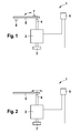
- Fig. 1 is a highly schematic representation of a windshield wiper system 1 for a motor vehicle.
- the windshield wiper system 1 comprises an electric drive motor which is equipped with a rotation angle sensor 3.
- the rotation angle sensor 3 detects the rotation angle of a motor shaft 4 (drive shaft) of the drive motor 2.
- a wiper arm 5 is connected to a wiper blade, not shown.
- the wiper arm 5 is oscillating reciprocally movable by means of the drive motor 2, wherein the wiper arm 5 in Fig. 1 located in a park location.
- the drive motor 2 is associated with an electronic control unit 6, which is signal-conducting connected to the rotation angle sensor 3 and which energizes the drive motor 2 in response to the specification of a driver via a steering column switch, not shown.
- the wiper arm 5 is associated with a trained as a switch sensor 7, each time the wiper arm 5 flips a lever of this switch, the wiper arm 5 switches the switch so sent from this a corresponding electrical signal to the control unit 6.
- the control unit 6 recognizes an unwanted movement out of the wiper arm 5 from its parking position, which is preferably located in a lower region of a windscreen or a rear window.
- the drive motor 2 is energized by the control unit 6 so that the wiper arm 5 is moved back into its parking position, wherein the achievement of the park position is detected by the rotation angle sensor 3.
- the energization of the drive motor 2 is interrupted immediately after reaching the parking position.
- the drive motor 2 is energized for a predetermined period of time, so that the wiper arm 5 is subjected to a force against a stop 8, to prevent the wiper arm 5, for example, due to unfavorable wind conditions, immediately unintentionally moved out of its parking position ,
- the sensor 7 does not necessarily have to be actuatable directly by the wiper arm 5. It is also conceivable to arrange the sensor 7 within the drive motor 2 or in the region of the drive motor 2, for example such that it can be actuated by the motor shaft 4 or a projection, not shown, on the motor shaft 4.
- Fig. 2 an alternative embodiment of a windshield wiper system 1 is shown.
- the windshield wiper system 1 comprises an electric drive motor 2 with a motor shaft 4, with which a wiper arm 5 is non-rotatably connected. Further, sitting on the motor shaft 4 designed as a rotation angle sensor sensor 7, which is signal-conducting connected to a control unit 6.
- a rotation angle sensor sensor 7 which is signal-conducting connected to a control unit 6.
- the wiper arm 5 in a parking position in a lower portion of a vehicle window. If the wiper arm 5 is moved out of its parking position when the drive motor 2 is not energized, this is detected by the sensor 7, the sensor 7 relaying corresponding incremental signals to the control unit 6.
- the control unit 6 is constructed so that it does not recognize immediately upon receipt of a first signal of the rotation angle sensor on an unwanted Herausverstellen the wiper arm 5 from its parking position. Only when the wiper arm 5 has exceeded a certain pivot angle, the sensor 7 configured as a rotation angle sensor has sent a certain number of signals to the control unit 6, and the control unit 6 simultaneously recognizes that the drive motor 2 is deactivated, it recognizes an unwanted moving out of the wiper arm 5 from its parking position and energized the drive motor 2 such that the wiper arm 5 is moved back into its parking position, wherein the achievement of the parking position is detected by the formed as a rotation angle sensor sensor 7.
- a pressure sensor designed as a sensor is actuated.
Landscapes
- Engineering & Computer Science (AREA)
- Mechanical Engineering (AREA)
- Control Of Electric Motors In General (AREA)
Applications Claiming Priority (1)
| Application Number | Priority Date | Filing Date | Title |
|---|---|---|---|
| DE200710028385 DE102007028385A1 (de) | 2007-06-20 | 2007-06-20 | Scheibenwischeranlage und Verfahren zum Betreiben einer Scheibenwischeranlage |
Publications (3)
| Publication Number | Publication Date |
|---|---|
| EP2006172A2 true EP2006172A2 (fr) | 2008-12-24 |
| EP2006172A3 EP2006172A3 (fr) | 2010-02-17 |
| EP2006172B1 EP2006172B1 (fr) | 2012-11-28 |
Family
ID=39761071
Family Applications (1)
| Application Number | Title | Priority Date | Filing Date |
|---|---|---|---|
| EP20080103633 Not-in-force EP2006172B1 (fr) | 2007-06-20 | 2008-04-21 | Installation d'essuie-glace et procédé de fonctionnement d'une installation d'essuie-glace |
Country Status (3)
| Country | Link |
|---|---|
| EP (1) | EP2006172B1 (fr) |
| DE (1) | DE102007028385A1 (fr) |
| ES (1) | ES2395465T3 (fr) |
Cited By (1)
| Publication number | Priority date | Publication date | Assignee | Title |
|---|---|---|---|---|
| WO2011138367A1 (fr) * | 2010-05-06 | 2011-11-10 | Ece | Circuit et procédé de commande pour moteur électrique, notamment d'entraînement d'essuie-glace |
Citations (1)
| Publication number | Priority date | Publication date | Assignee | Title |
|---|---|---|---|---|
| DE102005050774A1 (de) | 2005-10-24 | 2007-04-26 | Robert Bosch Gmbh | Scheibenwischanlage mit einer im Ruhezustand eines Wischerantriebs wirksamen Selbsthemmung |
Family Cites Families (2)
| Publication number | Priority date | Publication date | Assignee | Title |
|---|---|---|---|---|
| DE10312982A1 (de) * | 2003-03-24 | 2004-10-07 | Robert Bosch Gmbh | Scheibenwischvorrichtung, insbesondere für ein Kraftfahrzeug |
| DE102005062721A1 (de) * | 2005-12-28 | 2007-07-05 | Robert Bosch Gmbh | Antriebsvorrichtung |
-
2007
- 2007-06-20 DE DE200710028385 patent/DE102007028385A1/de not_active Withdrawn
-
2008
- 2008-04-21 ES ES08103633T patent/ES2395465T3/es active Active
- 2008-04-21 EP EP20080103633 patent/EP2006172B1/fr not_active Not-in-force
Patent Citations (1)
| Publication number | Priority date | Publication date | Assignee | Title |
|---|---|---|---|---|
| DE102005050774A1 (de) | 2005-10-24 | 2007-04-26 | Robert Bosch Gmbh | Scheibenwischanlage mit einer im Ruhezustand eines Wischerantriebs wirksamen Selbsthemmung |
Cited By (2)
| Publication number | Priority date | Publication date | Assignee | Title |
|---|---|---|---|---|
| WO2011138367A1 (fr) * | 2010-05-06 | 2011-11-10 | Ece | Circuit et procédé de commande pour moteur électrique, notamment d'entraînement d'essuie-glace |
| FR2959711A1 (fr) * | 2010-05-06 | 2011-11-11 | Ece | Circuit et procede de commande pour moteur electrique, notamment d'entrainement d'essuie-glace |
Also Published As
| Publication number | Publication date |
|---|---|
| ES2395465T3 (es) | 2013-02-12 |
| DE102007028385A1 (de) | 2008-12-24 |
| EP2006172A3 (fr) | 2010-02-17 |
| EP2006172B1 (fr) | 2012-11-28 |
Similar Documents
| Publication | Publication Date | Title |
|---|---|---|
| DE102007039439B4 (de) | Vorrichtung und Verfahren zur Steuerung einer Kopfstütze | |
| EP1994275B1 (fr) | Dispositif de branchement et de debranchement du moteur d'un véhicule en fonction de la situation du trafic | |
| DE102009044819B4 (de) | Wischersystem und Wischersteuerungsverfahren | |
| EP2252486B1 (fr) | Blocage automatique électronique pour un dispositif essuie-glace | |
| EP2117888B1 (fr) | Dispositif et procédé de commande d'une unité d'entraînement d'un système essuie-glace | |
| EP1943129B1 (fr) | Installation d'essuie-glace equipee d'un systeme de blocage automatique qui est actif lorsque l'entrainement de l'essuie-glace est a l'etat de repos | |
| EP0999959B1 (fr) | Dispositif d'essuie-glace | |
| DE102011088040B4 (de) | Verfahren zum Steuern der Position eines Sitzes unter Verwendung eines einzelnen Hall-Sensors | |
| DE102008019346A1 (de) | Verfahren und Vorrichtung zum automatischen Ein- und Ausparken eines Fahrzeugs | |
| DE102007029773A1 (de) | Parklenkassistenzsystem und Verfahren zum Unterstützen eines Ausparkvorgangs | |
| EP2841325A1 (fr) | Procédé pour le stationnement autonome d'un véhicule automobile, dispositif d'assistance au conducteur pour réaliser le procédé ainsi que véhicule automobile équipé d'un dispositif d'assistance au conducteur | |
| EP2303649A1 (fr) | Procédé de détection de l angle de rotation et d une position de marche arrière d une unité d entraînement - transmission | |
| DE102009045079B4 (de) | Wischanlage | |
| DE102012018099B4 (de) | Verfahren zum Betreiben einer Sensoreinrichtung eines Kraftwagens | |
| DE102015219920A1 (de) | System zum Steuern des Sprühens eines Waschfluids eines Scheibenwischerblatts | |
| WO2000047447A1 (fr) | Retroviseur exterieur pour vehicule et procede de reglage y relatif | |
| DE10053316B4 (de) | Kraftfahrzeug mit einer Karosserie mit Bugschürze | |
| DE102017221464A1 (de) | Elektrisch betriebenes Fahrzeug mit Kriechfunktion | |
| EP2274184B1 (fr) | Procédé de montage d'un bras d'essuie-glace, procédé d'ajustement ou d'opération d'un dispositif d'essuie-glace et un dispositif d'essuie-glace | |
| EP2473383B1 (fr) | Systeme d'essuie-glace et procede pour faire fonctionner ledit systeme | |
| EP0898528B1 (fr) | Dispositif et procede de commande d'essuie-glace | |
| EP2006172B1 (fr) | Installation d'essuie-glace et procédé de fonctionnement d'une installation d'essuie-glace | |
| DE19841659B4 (de) | Verfahren zur Steuerung einer Kraftstoffpumpe für ein Kraftfahrzeug | |
| EP1066180B1 (fr) | Mecanisme d'entrainement d'essuie-glace et vehicule equipe de ce dernier | |
| DE102018215526A1 (de) | Assistenzsystem für einen Kraftwagen und Kraftwagen |
Legal Events
| Date | Code | Title | Description |
|---|---|---|---|
| PUAI | Public reference made under article 153(3) epc to a published international application that has entered the european phase |
Free format text: ORIGINAL CODE: 0009012 |
|
| AK | Designated contracting states |
Kind code of ref document: A2 Designated state(s): AT BE BG CH CY CZ DE DK EE ES FI FR GB GR HR HU IE IS IT LI LT LU LV MC MT NL NO PL PT RO SE SI SK TR |
|
| AX | Request for extension of the european patent |
Extension state: AL BA MK RS |
|
| PUAL | Search report despatched |
Free format text: ORIGINAL CODE: 0009013 |
|
| AK | Designated contracting states |
Kind code of ref document: A3 Designated state(s): AT BE BG CH CY CZ DE DK EE ES FI FR GB GR HR HU IE IS IT LI LT LU LV MC MT NL NO PL PT RO SE SI SK TR |
|
| AX | Request for extension of the european patent |
Extension state: AL BA MK RS |
|
| 17P | Request for examination filed |
Effective date: 20100817 |
|
| 17Q | First examination report despatched |
Effective date: 20100910 |
|
| AKX | Designation fees paid |
Designated state(s): CZ DE ES FR HU |
|
| GRAP | Despatch of communication of intention to grant a patent |
Free format text: ORIGINAL CODE: EPIDOSNIGR1 |
|
| GRAS | Grant fee paid |
Free format text: ORIGINAL CODE: EPIDOSNIGR3 |
|
| GRAA | (expected) grant |
Free format text: ORIGINAL CODE: 0009210 |
|
| AK | Designated contracting states |
Kind code of ref document: B1 Designated state(s): CZ DE ES FR HU |
|
| REG | Reference to a national code |
Ref country code: DE Ref legal event code: R096 Ref document number: 502008008752 Country of ref document: DE Effective date: 20130124 |
|
| REG | Reference to a national code |
Ref country code: ES Ref legal event code: FG2A Ref document number: 2395465 Country of ref document: ES Kind code of ref document: T3 Effective date: 20130212 |
|
| PLBE | No opposition filed within time limit |
Free format text: ORIGINAL CODE: 0009261 |
|
| STAA | Information on the status of an ep patent application or granted ep patent |
Free format text: STATUS: NO OPPOSITION FILED WITHIN TIME LIMIT |
|
| 26N | No opposition filed |
Effective date: 20130829 |
|
| REG | Reference to a national code |
Ref country code: HU Ref legal event code: AG4A Ref document number: E017500 Country of ref document: HU |
|
| REG | Reference to a national code |
Ref country code: DE Ref legal event code: R097 Ref document number: 502008008752 Country of ref document: DE Effective date: 20130829 |
|
| PGFP | Annual fee paid to national office [announced via postgrant information from national office to epo] |
Ref country code: HU Payment date: 20140414 Year of fee payment: 7 |
|
| PG25 | Lapsed in a contracting state [announced via postgrant information from national office to epo] |
Ref country code: HU Free format text: LAPSE BECAUSE OF NON-PAYMENT OF DUE FEES Effective date: 20150422 |
|
| REG | Reference to a national code |
Ref country code: FR Ref legal event code: PLFP Year of fee payment: 9 |
|
| REG | Reference to a national code |
Ref country code: FR Ref legal event code: PLFP Year of fee payment: 10 |
|
| PGFP | Annual fee paid to national office [announced via postgrant information from national office to epo] |
Ref country code: CZ Payment date: 20170410 Year of fee payment: 10 |
|
| PGFP | Annual fee paid to national office [announced via postgrant information from national office to epo] |
Ref country code: ES Payment date: 20170503 Year of fee payment: 10 |
|
| REG | Reference to a national code |
Ref country code: FR Ref legal event code: PLFP Year of fee payment: 11 |
|
| PGFP | Annual fee paid to national office [announced via postgrant information from national office to epo] |
Ref country code: FR Payment date: 20180424 Year of fee payment: 11 |
|
| PGFP | Annual fee paid to national office [announced via postgrant information from national office to epo] |
Ref country code: DE Payment date: 20180627 Year of fee payment: 11 |
|
| PG25 | Lapsed in a contracting state [announced via postgrant information from national office to epo] |
Ref country code: CZ Free format text: LAPSE BECAUSE OF NON-PAYMENT OF DUE FEES Effective date: 20180421 |
|
| REG | Reference to a national code |
Ref country code: ES Ref legal event code: FD2A Effective date: 20190912 |
|
| PG25 | Lapsed in a contracting state [announced via postgrant information from national office to epo] |
Ref country code: ES Free format text: LAPSE BECAUSE OF NON-PAYMENT OF DUE FEES Effective date: 20180422 |
|
| REG | Reference to a national code |
Ref country code: DE Ref legal event code: R119 Ref document number: 502008008752 Country of ref document: DE |
|
| PG25 | Lapsed in a contracting state [announced via postgrant information from national office to epo] |
Ref country code: DE Free format text: LAPSE BECAUSE OF NON-PAYMENT OF DUE FEES Effective date: 20191101 |
|
| PG25 | Lapsed in a contracting state [announced via postgrant information from national office to epo] |
Ref country code: FR Free format text: LAPSE BECAUSE OF NON-PAYMENT OF DUE FEES Effective date: 20190430 |