EP2006192B1 - Fahrzeugaufbauplatte - Google Patents
Fahrzeugaufbauplatte Download PDFInfo
- Publication number
- EP2006192B1 EP2006192B1 EP20080010358 EP08010358A EP2006192B1 EP 2006192 B1 EP2006192 B1 EP 2006192B1 EP 20080010358 EP20080010358 EP 20080010358 EP 08010358 A EP08010358 A EP 08010358A EP 2006192 B1 EP2006192 B1 EP 2006192B1
- Authority
- EP
- European Patent Office
- Prior art keywords
- opening
- vehicle body
- panel
- body panel
- vehicle
- Prior art date
- Legal status (The legal status is an assumption and is not a legal conclusion. Google has not performed a legal analysis and makes no representation as to the accuracy of the status listed.)
- Ceased
Links
- 230000003014 reinforcing effect Effects 0.000 description 3
- 210000003734 kidney Anatomy 0.000 description 2
- 239000000463 material Substances 0.000 description 2
- 239000002184 metal Substances 0.000 description 2
- 238000000034 method Methods 0.000 description 2
- 241001236644 Lavinia Species 0.000 description 1
- 238000009420 retrofitting Methods 0.000 description 1
Images




Classifications
-
- B—PERFORMING OPERATIONS; TRANSPORTING
- B62—LAND VEHICLES FOR TRAVELLING OTHERWISE THAN ON RAILS
- B62D—MOTOR VEHICLES; TRAILERS
- B62D25/00—Superstructure or monocoque structure sub-units; Parts or details thereof not otherwise provided for
- B62D25/24—Superstructure sub-units with access or drainage openings having movable or removable closures; Sealing means therefor
-
- B—PERFORMING OPERATIONS; TRANSPORTING
- B60—VEHICLES IN GENERAL
- B60D—VEHICLE CONNECTIONS
- B60D1/00—Traction couplings; Hitches; Draw-gear; Towing devices
- B60D1/48—Traction couplings; Hitches; Draw-gear; Towing devices characterised by the mounting
- B60D1/485—Traction couplings; Hitches; Draw-gear; Towing devices characterised by the mounting mounted by means of transversal members attached to the frame of a vehicle
-
- B—PERFORMING OPERATIONS; TRANSPORTING
- B60—VEHICLES IN GENERAL
- B60D—VEHICLE CONNECTIONS
- B60D1/00—Traction couplings; Hitches; Draw-gear; Towing devices
- B60D1/48—Traction couplings; Hitches; Draw-gear; Towing devices characterised by the mounting
- B60D1/488—Traction couplings; Hitches; Draw-gear; Towing devices characterised by the mounting mounted directly to the chassis of the towing vehicle
-
- B—PERFORMING OPERATIONS; TRANSPORTING
- B62—LAND VEHICLES FOR TRAVELLING OTHERWISE THAN ON RAILS
- B62D—MOTOR VEHICLES; TRAILERS
- B62D25/00—Superstructure or monocoque structure sub-units; Parts or details thereof not otherwise provided for
- B62D25/08—Front or rear portions
Definitions
- the present invention relates to a vehicle body panel, and in particular to a vehicle body panel including a part that can be readily removed so as to form an opening as required even after the body panel is assembled to a vehicle body.
- a tow hook is provided in a front part or rear part of a vehicle for towing another vehicle or being towed by another vehicle.
- a motor vehicle is often fitted with a trailer hitch for towing a camping trailer, a transport trailer such as those for towing a boat or jet ski.
- trailer hitches are typically directly attached to vehicle body frames having a high rigidity so as to withstand the large load applied to the hook or hitch as the case may be by the vehicle to be towed and (by the vehicle in question when the vehicle itself is to be towed).
- US 5511813 discloses a hitch assembly for connecting a towed vehicle to a towing vehicle having a pair of longitudinally extending frame portions.
- the hitch assembly is attachable to a selected vehicle of a group of towing vehicles having frame portions spaced apart a variety of different widths.
- the hitch assembly includes a pair of end members. Each end member has an attachment connectable with a respective frame portion of the towing vehicle and a support fixed to the attachment.
- Each attachment has a plurality of elongate openings each for receiving a fastener to attach its end member to the frame portion of the towing vehicle. At least one of the attachment elongate openings in each attachment extends in a direction parallel to the support.
- At least one of the elongate transverse openings extends in a direction perpendicular to the support.
- the support has at least one elongate transverse opening extending in a direction parallel to the length of the support and a transverse circular opening.
- An intermediate member defining a longitudinally extending opening.
- the intermediate member opening receives a support of a respective end member in a telescoping relationship.
- the intermediate member has a length .less than the smallest width between frame portions of the numerous towing vehicles.
- the intermediate member includes at least one transverse opening which extends transversely through a portion of said intermediate member to receive a fastener extending through a traverse opening in the support to connect the intermediate member to the support.
- a front part of the vehicle is often provided with a crash portion (impact absorbing portion).
- the tow hook extends most away from the vehicle body than any other part, it is often subjected to the impact load before any other part of the vehicle body. Therefore, there is a need to mount the tow hook in such a way that the tow hook does not diminish the effectiveness of the crash portion at the time of an impact and at the same time does not protrude excessively from the outer profile of the vehicle body.
- a previously proposed tow hook comprises a hook mount which is fixedly attached to a front end of a front frame of a vehicle, a curved portion which depends from a lower end of the hook mount and curves toward the vehicle and an engagement portion which extends away from the vehicle. See Japanese patent laid open publication No. 10-7032 .
- the previously proposed tow hook can be mounted on the outer end of the crash portion so as not to interfere with the operation of the crash portion at the time of a crash but does not excessively protrude outwardly from the vehicle body owing to the provision of the curved portion.
- Such a tow hook is typically provided in all of the vehicles, but a trailer hitch is often optional. Some vehicles of a particular model may be fitted with a trailer hitch but others may not be fitted with a trailer hitch. Oftentimes, a trailer hitch is retrofitted to a vehicle which is already put in use.
- a frame member such as a rear side frame is selected for such a purpose, but it is often closed by an outer panel such as a rear panel. Therefore, to mount a hitch to a frame member, and an opening is required to be formed in the outer panel.
- an opening is formed in the outer panel of each vehicle without regard to the need for a trailer hitch. In some cases, such an opening may be closed by a lid made of plastic material.
- the outer panel must be designed to have an adequate mechanical strength without regard to the presence or absence of such an opening. Therefore, if the outer panel is to have a required mechanical strength when such an opening is formed, the outer panel is required to be reinforced by using an increased amount of material or increasing the thickness of the outer panel.
- a primary object of the present invention is to provide a vehicle body panel which can be formed with an opening only when required, and is otherwise given with a high mechanical strength owing to the absence of such an opening.
- a second object of the present invention is to provide a vehicle body panel which can be easily formed with an opening even when the vehicle body panel is assembled to the vehicle body.
- a vehicle body panel through which an opening may be formed as an option, comprising: a panel member including a plurality of slots arranged along an imaginary line defining the optional opening; and a guide feature for guiding a hole opening tool is provided between each selected pair of slots.
- the panel member when the optional opening is absent, the panel member is free from an opening which does not serve any useful purpose other than reducing the mechanical strength and rigidity of the panel member, and is enabled to retain a substantially same mechanical strength and/or rigidity as having no opening or nor arrangement for forming an optional opening. Therefore, the provision of the arrangement for forming the optional opening does not substantially add to the weight of the vehicle body.
- the optional opening By forming drill holes around the guide features using them as a guide so as to connect all of the slots, the optional opening can be readily formed even when the panel member is already assembled to the vehicle body. If desired, a reinforcing arrangement may be made only when the optional opening is formed.
- each slot is given with an elongated track shape which extends along the edge of the optional opening.
- each slot may be given with an elongated curved track shape or a kidney shape.
- each guide feature may be provided inside the imaginary line defining the optional opening.
- the guide feature typically consists of dimples, but may also consist of small holes or slits as long as they can be used as a centering guide for a hole forming tool.
- the panel member comprises a rear panel, and the opening provides an access for mounting a trailer hitch to a side frame disposed in front of the rear panel.
- a vehicle body panel which can be formed with an opening only when required, and is otherwise given with a high mechanical strength owing to the absence of such an opening.
- the body panel includes a plurality of slots arranged along an imaginary line defining the optional opening, and a guide feature for guiding a hole opening tool is provided between each selected pair of slots.
- the optional opening is absent, the panel is free from an opening which does not serve any useful purpose other than reducing the mechanical strength and rigidity of the panel, and is enabled to retain a substantially same mechanical strength and/or rigidity as having no opening or nor arrangement for forming an optional opening. Therefore, the provision of the arrangement for forming the optional opening does not substantially add to the weight of the vehicle body.
- the optional opening can be readily formed by forming drill holes that connect the slots one another by using the guide feature such as dimples as a guide.
- a motor vehicle 1 embodying the present invention is provided with a trailer hitch 11 in a rear end thereof, and a hitch ball member 16 for engaging a vehicle to be hitched extends rearward from under a rear bumper 2.
- a rear part of the vehicle body includes a rear cross member 3 extending in a lower part of the vehicle body along the front edge of a trunk room, and a pair of rear side frames 4 and 5 extending rearward from either lateral end of the rear cross member 3.
- a rear panel 6 extends across the rear ends of the rear side frames 4 and 5, and the rear bumper 2 extends laterally at a small distance from the rear side of the rear panel 6.
- a trailer hitch assembly 11 is also attached across the rear ends of the rear side frames 4 and 5, and is in most part concealed behind the rear bumper 2.
- the trailer hitch assembly 11 includes a hitch cross member 14 consisting of a pipe having a rectangular cross section, a pair of hitch mounts 12 and 13 joining the two ends of the hitch cross member 14 to the rear ends of the corresponding rear side frames 4 and 5, a ball mount 15 depending from a middle part of the hitch cross member 14 and the aforementioned hitch ball member 16 supported by the ball mount 15 and extending rearward. Because the trailer hitch assembly 11 is subjected to a significant load when towing an object to be towed, the hitch mounts 12 and 13 are directly attached to the corresponding rear side frames 4 and 5 having a high rigidity.
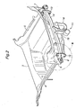
- FIG. 3 shows the left hitch mount 12 in an enlarged scale.
- the hitch cross member 14 extends in a rearwardly spaced relationship with respect to the rear panel 6 so that the hitch mount 12 includes a part that is passed through an opening 8 provided in the rear panel 6.
- the front end of the hitch mount 12 is passed into this opening 8 and is connected to the rear end of the corresponding rear side frame 4 inside the rear panel 6 by using threaded bolts (not shown in the drawings) in a per se known manner.
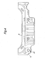
- Figure 4 shows a front view (as seen from the rear end of the vehicle body) of the rear panel 6 before the trailer hitch 11 is mounted
- Figure 5 shows a part of Figure 4 indicated by a circle V in Figure 4 in an enlarged scale.
- Figures 4 and 5 show the rear panel 6 before the opening 8 is formed, and the part where the opening 8 may be optionally formed or opening forming part is denoted with numeral 21.
- the opening forming part 21 includes a plurality of slots 22 arranged along an imaginary line 21a, that defines the edge of the opening 8 to be formed, at a regular interval with each long side of the slot extending along the imaginary line 21a.
- a dimple 24 is formed in a mid point between each pair of adjacent slots 22.
- each dimple 24 is set back toward the center of the opening 8 to be formed by a certain distance. More specifically, the position of each dimple 24 is determined in such a manner that a drill hole of a prescribed radius centered around the dimple 24 cuts through the adjacent slots 22.
- each dimple 24 when a drill hole of the prescribed radius is formed around each dimple 24, all of the slots 22 are connected by the drilled holes, and the opening 8 is formed as defined by the imaginary line 21a and slots 22 after a piece of sheet metal is removed from the central part of the opening forming part 21.
- the dimples 24 as well as slots 24 may be formed at the time of stamp forming the rear panel 6.
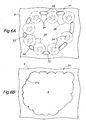
- FIGs 6A and 6B illustrate the procedure for forming the opening 8 in the opening forming part 21 of the rear panel 6.
- a hole opening tool such as a drill, a hole saw, a punch and the like
- drill holes 25 are formed in the opening forming part 21 as indicated by the imaginary circular lines centered around the dimples 24 in Figure 6A .
- the drill holes 25 are dimensioned and positioned so as to overlap with the adjacent slots 22. Therefore, the slots 22 are completely connected with one another by the drill holes 25 and the opening 8 is formed as illustrated in Figure 6B after the piece of sheet metal surrounded by the drill holes 25 and slots 22 is removed.
- the opening 8 can be made without any difficulty even on a vehicle body of a finished vehicle or when retrofitting a trailer hitch to a vehicle which is already in use.
- the opening forming part 21 may be kept intact, and this contributes to the mechanical strength of the rear panel 6.
- the slots 22 are relatively widely spaced from one another, the negative impact of these slots 22 to the mechanical strength of the rear panel 6 is minimized.
- a reinforcing measure may be taken as required by using any known reinforcing arrangement.
- each slot 22 was given with an elongated track shape, but slots may be given with other shapes as long as they may be connected with one another by drill holes formed around the dimples 24.
- each slot 22' is given with the shape of a curved track or is kidney shaped so that the part of the edge of the opening 8 formed by the drill holes denoted with numeral 21 a may smoothly connect with the part of the edge of the opening 8 formed by the slots 22', and the overall edge of the opening 8 may be relatively free from ruggedness.
- the dimples 24 in the illustrated embodiment each consisted of a semispherical recess (projection as seen from the opposite side of the rear panel 6), by may also consist of small holes 24' or slits passed through the rear panel 6 as illustrated in Figure 8 or dimples of other shapes as long as they can be used for centering a drill or other hole forming tools.
- the opening 8 may not be a complete opening in the rear panel 6, but may also consist of a cutout or notch which is cut out from a fringe part of the rear panel 6.
- the vehicle panel of the present invention is not limited to a rear panel or a part through which a trailer hitch is to be passed, but may consist of any other body panel part of a vehicle body through which an opening may be formed as an option.
Landscapes
- Engineering & Computer Science (AREA)
- Transportation (AREA)
- Mechanical Engineering (AREA)
- Chemical & Material Sciences (AREA)
- Combustion & Propulsion (AREA)
- Body Structure For Vehicles (AREA)
- Connection Of Plates (AREA)
Claims (7)
- Fahrzeugaufbauplatte, durch die hindurch, als Option, eine Öffnung (8) ausgebildet werden kann, umfassend:ein Plattenelement (6), das eine Mehrzahl von Schlitzen (22) enthält, die entlang einer die optionale Öffnung (8) definierenden imaginären Linie (21 a) angeordnet sind; undein Führungsmerkmal (24) zum Führen eines Lochöffnungswerkzeugs zwischen jedem gewählten Paar von Schlitzen (22) vorgesehen ist.
- Fahrzeugaufbauplatte nach Anspruch 1, worin jeder Schlitz (22) eine langgestreckte Bahnform hat.
- Fahrzeugaufbauplatte nach Anspruch 1, worin jeder Schlitz (22') eine langgestreckte gekrümmte Bahnform hat.
- Fahrzeugaufbauplatte nach Anspruch 1, worin jedes Führungsmerkmal (24) innerhalb der die optionale Öffnung (8) definierenden imaginären Linie (21) vorgesehen ist.
- Fahrzeugaufbauplatte nach Anspruch 1, worin jedes Führungsmerkmal eine in dem Plattenelement (6) ausgebildete Delle (24') aufweist.
- Fahrzeugaufbauplatte nach Anspruch 1, worin jedes Führungsmerkmal ein Loch oder einen Schlitz aufweist, das/der in dem Plattenelement (6) ausgebildet ist.
- Fahrzeugaufbauplatte nach Anspruch 1, worin das Plattenelement (6) eine Heckplatte (6) aufweist, und die Öffnung (8) einen Zugang zum Anbringen einer Anhängerkupplung (11) an einem vor der Heckplatte (6) angeordneten Seitenrahmen bietet.
Applications Claiming Priority (1)
| Application Number | Priority Date | Filing Date | Title |
|---|---|---|---|
| JP2007163447A JP4377930B2 (ja) | 2007-06-21 | 2007-06-21 | 車体パネル |
Publications (2)
| Publication Number | Publication Date |
|---|---|
| EP2006192A1 EP2006192A1 (de) | 2008-12-24 |
| EP2006192B1 true EP2006192B1 (de) | 2009-08-19 |
Family
ID=39677663
Family Applications (1)
| Application Number | Title | Priority Date | Filing Date |
|---|---|---|---|
| EP20080010358 Ceased EP2006192B1 (de) | 2007-06-21 | 2008-06-06 | Fahrzeugaufbauplatte |
Country Status (4)
| Country | Link |
|---|---|
| EP (1) | EP2006192B1 (de) |
| JP (1) | JP4377930B2 (de) |
| CN (1) | CN101327808B (de) |
| DE (1) | DE602008000101D1 (de) |
Families Citing this family (3)
| Publication number | Priority date | Publication date | Assignee | Title |
|---|---|---|---|---|
| DE10108225A1 (de) | 2001-02-21 | 2002-10-10 | Basf Ag | Verfahren zur Herstellung von D-Pantothensäure und/oder deren Salze als Zusatz zu Tierfuttermitteln |
| DE102015100490A1 (de) * | 2015-01-14 | 2016-07-14 | Scambia Holdings Cyprus Limited | Anhängekupplung |
| JP6282302B2 (ja) * | 2016-03-31 | 2018-02-21 | 本田技研工業株式会社 | 車体構造および車両の製造方法 |
Family Cites Families (3)
| Publication number | Priority date | Publication date | Assignee | Title |
|---|---|---|---|---|
| CA2144137C (en) * | 1994-03-07 | 2000-08-22 | Harley A. Kravitz | Adjustable width trailer hitch |
| JP3345272B2 (ja) | 1996-06-25 | 2002-11-18 | ダイハツ工業株式会社 | 車両用牽引フックの構造 |
| DE102004006841A1 (de) * | 2004-02-12 | 2005-09-08 | Opel Eisenach Gmbh | Montageöffnung an einer Karosserie eines Kraftfahrzeuges |
-
2007
- 2007-06-21 JP JP2007163447A patent/JP4377930B2/ja not_active Expired - Fee Related
-
2008
- 2008-05-21 CN CN200810099324XA patent/CN101327808B/zh not_active Expired - Fee Related
- 2008-06-06 DE DE200860000101 patent/DE602008000101D1/de active Active
- 2008-06-06 EP EP20080010358 patent/EP2006192B1/de not_active Ceased
Also Published As
| Publication number | Publication date |
|---|---|
| DE602008000101D1 (de) | 2009-10-01 |
| CN101327808A (zh) | 2008-12-24 |
| CN101327808B (zh) | 2010-06-23 |
| JP2009001134A (ja) | 2009-01-08 |
| EP2006192A1 (de) | 2008-12-24 |
| JP4377930B2 (ja) | 2009-12-02 |
Similar Documents
| Publication | Publication Date | Title |
|---|---|---|
| US10604077B2 (en) | Modular rail and step system | |
| US5570826A (en) | Hitch socket mounted collision guard and utility platform | |
| US8322763B2 (en) | Front bumper arrangement for a truck for single or dual tow points | |
| CA2670173C (en) | Roof rack with stowable non-adjustable crossbars | |
| US5511813A (en) | Adjustable width trailer hitch | |
| CN111661161B (zh) | 一种用于车辆的拖车装置及车辆 | |
| US20060201980A1 (en) | Vehicle mounting systems | |
| JP4454121B2 (ja) | 車両用牽引フックの取付構造 | |
| EP2054246B1 (de) | Stossfängerstange für ein fahrzeug | |
| US11932066B2 (en) | Safety chain engaging device for gooseneck hitch | |
| EP2006192A1 (de) | Fahrzeugaufbauplatte | |
| EP1467878B1 (de) | Zughakensystem | |
| CN115195367A (zh) | 挂车挂接总成 | |
| CN106945726B (zh) | 汽车拖钩及汽车纵梁 | |
| JP2005186846A (ja) | 自動車用着脱式牽引フック取付構造 | |
| US20240227474A9 (en) | Adjustable tow hook assemblies and vehicles including same | |
| CN213973902U (zh) | 车辆防护栏总成和车辆 | |
| JP2006321407A (ja) | 自動車の車体前部構造 | |
| US12472785B2 (en) | Collapsing tow hook assemblies and vehicles including same | |
| US12617247B2 (en) | Tow hook assemblies and vehicles including same | |
| US20140054876A1 (en) | Vehicle receiver assembly with cargo anchor point(s) for supporting and securing cargo, cargo carriers, cargo carrier accessories, and tow-hitch receiver accessories | |
| CN205131394U (zh) | 一种汽车后围板总成及汽车 | |
| EP3718816A1 (de) | Leichter c-ring-querträger und halterungsanordnung für ein fahrzeug | |
| AU2007100991A4 (en) | A towbar assembly | |
| DE102011115939A1 (de) | Anordnung eines Emblems am Ende eines Kraftwagens |
Legal Events
| Date | Code | Title | Description |
|---|---|---|---|
| PUAI | Public reference made under article 153(3) epc to a published international application that has entered the european phase |
Free format text: ORIGINAL CODE: 0009012 |
|
| 17P | Request for examination filed |
Effective date: 20080606 |
|
| AK | Designated contracting states |
Kind code of ref document: A1 Designated state(s): AT BE BG CH CY CZ DE DK EE ES FI FR GB GR HR HU IE IS IT LI LT LU LV MC MT NL NO PL PT RO SE SI SK TR |
|
| AX | Request for extension of the european patent |
Extension state: AL BA MK RS |
|
| GRAP | Despatch of communication of intention to grant a patent |
Free format text: ORIGINAL CODE: EPIDOSNIGR1 |
|
| GRAS | Grant fee paid |
Free format text: ORIGINAL CODE: EPIDOSNIGR3 |
|
| GRAA | (expected) grant |
Free format text: ORIGINAL CODE: 0009210 |
|
| RIN1 | Information on inventor provided before grant (corrected) |
Inventor name: MATSUNAGA, KOJI,C/O HONDA ACCESS CORP. Inventor name: HORIGUCHI, JUNC/O HONDA R&D CO., LTD. |
|
| AK | Designated contracting states |
Kind code of ref document: B1 Designated state(s): DE GB |
|
| REG | Reference to a national code |
Ref country code: GB Ref legal event code: FG4D |
|
| AKX | Designation fees paid |
Designated state(s): DE GB |
|
| REF | Corresponds to: |
Ref document number: 602008000101 Country of ref document: DE Date of ref document: 20091001 Kind code of ref document: P |
|
| PLBE | No opposition filed within time limit |
Free format text: ORIGINAL CODE: 0009261 |
|
| STAA | Information on the status of an ep patent application or granted ep patent |
Free format text: STATUS: NO OPPOSITION FILED WITHIN TIME LIMIT |
|
| 26N | No opposition filed |
Effective date: 20100520 |
|
| PGFP | Annual fee paid to national office [announced via postgrant information from national office to epo] |
Ref country code: GB Payment date: 20140604 Year of fee payment: 7 |
|
| PGFP | Annual fee paid to national office [announced via postgrant information from national office to epo] |
Ref country code: DE Payment date: 20140603 Year of fee payment: 7 |
|
| REG | Reference to a national code |
Ref country code: DE Ref legal event code: R119 Ref document number: 602008000101 Country of ref document: DE |
|
| GBPC | Gb: european patent ceased through non-payment of renewal fee |
Effective date: 20150606 |
|
| PG25 | Lapsed in a contracting state [announced via postgrant information from national office to epo] |
Ref country code: DE Free format text: LAPSE BECAUSE OF NON-PAYMENT OF DUE FEES Effective date: 20160101 Ref country code: GB Free format text: LAPSE BECAUSE OF NON-PAYMENT OF DUE FEES Effective date: 20150606 |