EP2006234A2 - Ascenseur modulaire équipé d'une cabine automotrice montée sur un mât - Google Patents
Ascenseur modulaire équipé d'une cabine automotrice montée sur un mât Download PDFInfo
- Publication number
- EP2006234A2 EP2006234A2 EP07730451A EP07730451A EP2006234A2 EP 2006234 A2 EP2006234 A2 EP 2006234A2 EP 07730451 A EP07730451 A EP 07730451A EP 07730451 A EP07730451 A EP 07730451A EP 2006234 A2 EP2006234 A2 EP 2006234A2
- Authority
- EP
- European Patent Office
- Prior art keywords
- cabin
- mast
- rack
- motorised
- pinions
- Prior art date
- Legal status (The legal status is an assumption and is not a legal conclusion. Google has not performed a legal analysis and makes no representation as to the accuracy of the status listed.)
- Withdrawn
Links
Images


Classifications
-
- B—PERFORMING OPERATIONS; TRANSPORTING
- B66—HOISTING; LIFTING; HAULING
- B66B—ELEVATORS; ESCALATORS OR MOVING WALKWAYS
- B66B9/00—Kinds or types of lifts in, or associated with, buildings or other structures
- B66B9/16—Mobile or transportable lifts specially adapted to be shifted from one part of a building or other structure to another part or to another building or structure
- B66B9/187—Mobile or transportable lifts specially adapted to be shifted from one part of a building or other structure to another part or to another building or structure with a liftway specially adapted for temporary connection to a building or other structure
-
- B—PERFORMING OPERATIONS; TRANSPORTING
- B66—HOISTING; LIFTING; HAULING
- B66B—ELEVATORS; ESCALATORS OR MOVING WALKWAYS
- B66B9/00—Kinds or types of lifts in, or associated with, buildings or other structures
- B66B9/02—Kinds or types of lifts in, or associated with, buildings or other structures actuated mechanically otherwise than by rope or cable
- B66B9/022—Kinds or types of lifts in, or associated with, buildings or other structures actuated mechanically otherwise than by rope or cable by rack and pinion drives
-
- B—PERFORMING OPERATIONS; TRANSPORTING
- B66—HOISTING; LIFTING; HAULING
- B66B—ELEVATORS; ESCALATORS OR MOVING WALKWAYS
- B66B9/00—Kinds or types of lifts in, or associated with, buildings or other structures
- B66B9/16—Mobile or transportable lifts specially adapted to be shifted from one part of a building or other structure to another part or to another building or structure
Definitions
- the object of this invention is a modular elevator with a self-propelled cabin on a mast, which offers new essential characteristics and notable advantages over similar means and devices known in the current technical scene.
- the invention refers to rack and pinion drive elevator, with a mobile element with a cabin and a modular load-bearing member, made of sections of mast that adapt to any construction, permanent or non-permanent. It is used to carry people and/or loads, as well as to carry out high-rise work.
- the invention has developed a modular elevator which is described in detail below.
- the parts and components that make up the mobile element have been assembled and the load-bearing member has been fixed in a new, practical and advantageous way.
- This way the elevator can be as compact as possible and the load-bearing member can be nearer to the enclosure in which the elevator is going to operate, and it can also be installed in small spaces without compromising safety, efficiency and comfort.
- the modular elevator to transport of people and/or loads that is shown therein includes a modular load-bearing member and a mobile element that make up the actual elevator.
- the construction in which the elevator is going to operate can be permanent or non-permanent.
- the load-bearing member is made of modules that consist of sections of the mast, of structural tube, with the rack fixed at the end of each side, screwed together at each end. These sections of the mast are anchored to the construction with bracing that adapts to the type of application of the elevator.
- the elevator can be built in sections - operators can assemble sections of the mast, one on top of another, and at the same time they can join the fixing devices to the masts in order to anchor the modules to the construction. To disassemble the elevator, the order of this procedure is reversed.
- the mobile element is a cabin with a frame with the rolling and guiding elements of the elevator, the drive groups, the parachute brake (if there is one), the suspension organs and the button panel. All these elements are integrated in a parallelepiped, enclosed all around.
- the main purpose is to protect people, the load and the elements of the drive groups, the parachute brake (if there is one), and control elements, which are housed inside.
- the cabin has access doors, windows, a trapdoor on the floor and a hatch on the ceiling to get out of the cabin. There are also lower and upper safety trays to detect any possible obstacle that may be in the way of the elevator.
- This configuration reduces the surface of the mobile element base notably, while keeping the dimensions inside. It also enables access from the inside of the cabin to all the necessary elements for the elevator to work properly.
- the cabin and the frame are one single unit, made up of welded square tubes with the profiles folded in 'b', forming a parallelepiped.
- the profiles folded in 'b' are placed in parallel position at the front of the cabin and they guide the guillotine door to enter the elevator.
- the tubes are joined together with the top and lower crossbeams, which form a vertical rectangular frame. Half-way up there is a square tube that divides this area in two areas of different sizes. The lower one (which will be used as entrance and exit to the cabin) is larger than the top one (which will be used as a window).
- Parallel to the previous elements there is another rectangular wall on the cabin, formed by square tubes that are welded together. The four corners of both the wall structures described above are joined together with horizontal square tubes, which close the parallelepiped shape.
- the back wall is made of 3 vertical square tubes, welded to a top crossbeam and a lower crossbeam, forming a vertical rectangular frame. Both the top and lower crossbeams are square tubes.
- the central vertical tube divides the rectangle in two sections of the same size, approx. Looking from the entrance towards the mast, on the section on the left there is a series of horizontal round tubes welded onto both vertical jambs. The tubes are placed at the same distance from each other, forming a vertical ladder inside the cabin.
- the horizontal tubes and the vertical jambs are joined together with arms, like lugs, that separate the steps from the cabin wall.
- On the lower part of this section there is an eyebolt welded between two square tubes that join the central vertical tube and the left vertical one. Just above half-way up the left area, there is a horizontal square tube that joins both vertical jambs, to reinforce the structure.
- This layout keeps both elements engaged during the whole path.
- the direction of the path is affected by the layout and shape of the construction to which the modules have to be attached to form the load-bearing member.
- Each drive group and the parachute brake are protected with a metal cover, which prevents occupants in the cabin from getting trapped accidentally and facilitates the access to the drive groups and/or parachute from inside the cabin.
- These covers have slits where the release levers for the motor brakes are installed, while the central area has a button panel to operate the elevator from inside.
- This button panel rests on a vertical 'U'-shaped support, which is joined to a horizontal angular profile (on the lower part), and to a horizontal arm (on the top part), which are joined to the vertical jambs.
- the rest of the surface of the back wall has a perforated sheet to prevent people from getting trapped.
- the left wall of the cabin parallelepiped, looking from the entrance, is divided by two horizontal square tubes in three areas of different sizes. Both these tubes are welded very closely together and they are used to place a welded eyebolt between them on the outside of the cabin. Out of the remaining areas, the lower one is larger than the top one. The top one is used for a window and the lower and central ones are closed by a perforated sheet.
- the right wall of the cabin parallelepiped, looking from the entrance, is closed with a perforated sheet, where there is a slit at one end of the rectangle, near the access door and a just above the centre of the rectangle.
- the release lever for the access door can be found in that slit.
- On the top of this wall there is a support that is made of three square tubes, which form a rectangle with the top horizontal crossbeam. It supports the electrical cabinet of the elevator, which is screwed onto two strips that are welded onto the support.
- the modular load-bearing member rises vertically above the construction, between the jambs of the self-propelled cabin on a mast in the existing space between the guide rollers and the drive pinions.
- All four back guide rollers project above four square tubes that are welded perpendicularly to the back wall of the cabin, specifically two on the top crossbeam and two on the lower crossbeam. These tubes are stiffened by square tubes that join the ends of the crossbeams and project above them. On one of the top stiffeners there is a support where the limit switches of the end of the elevator path are assembled.
- These rollers are placed at about 45° from the back wall of the cabin, with supports welded onto the ends of the previously mentioned tubes. The rollers guide the cabin on the back corners of the mast.
- the mast inductive sensor On the support of one of the top rollers there is a welded support for the mast inductive sensor.
- the path On the front of the mast, the path is guided with three rollers, one on the top part and two on the lower part.
- the roller support On the top part, the roller support is welded to the horizontal crossbeam of the cabin and is placed at about 45° from the back wall of the cabin, to guide the path on the corner of the mast that is opposite to where the rack is welded.
- On the lower part there is a roller support welded at the same angle as the one described for the top part, to guide the path on the same corner of the mast.
- the other guide roller is welded to the crossbeam, perpendicular to the back wall. That way the path is guided on the flat side of the mast, in a position that is near the corner where the rack is welded.
- this modular elevator with a self-propelled cabin on mast can be seen in the description above. It adapts to any kind of permanent or non-permanent construction. It is versatile because all the elements have been made as compact as possible, and because it is efficient and safe while moving. This is achieved because the cabin is well engaged to the load-bearing member (mast), it is easy to assemble and to carry out maintenance, and because it is possible to have access to all the elements of the elevator from the cabin.
- the use of the structural tube mast also enables the assembly of the elevator, keeping the original service staircase in the construction. The elevator can be assembled in the shaft and it is normally placed between the original staircase and the wall of the construction.
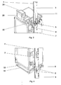
- Figure 1 shows that the load-bearing member (1) is fixed to the mobile element (2), it is made up of many modules (3), each one of them consisting of a section of the structural tube mast, with the rack (4) fixed to the end of one of their sides, screwed by the adjoining ends and anchored to the construction with bracing that adapts to the type of application of the elevator.
- the load-bearing member (1) enables operators to build the elevator in sections - operators can assemble sections of the mast, one on top of another, and at the same time they can join the fixing devices to the masts in order to anchor the modules to the construction. Logically, to disassemble the elevator the order of this procedure has to be reversed.
- the mobile element (2) is a cabin with a frame with the rolling and guiding elements (5) of the elevator, the pinions (7), the drive groups (6), the parachute brake (33) and the button panel (8).
- the button panel can be seen in Figure 2 . They are all integrated in a parallelepiped that is enclosed all around.
- the cabin has access doors, windows (9), a trapdoor on the floor (10) and a hatch on the ceiling (11) to get out of the cabin.
- the cabin and the frame form one continuous piece in this lift which is made up of square tubes and masts folded to form a "b" (13) that are welded together to make a parallelepiped.
- the masts folded in "b" (13) are parallel in the front part of the cabin and act as a guide for the sliding guillotine doors that make the access to the lift.
- These tubes are connected together by means of a lower cross beam (15), making a rectangular frame in the vertical plane.
- a square tube (16) that divides this area into two unequal sections, with the lower one being used to access and exit the cabin as it is larger than the upper one which will be used as a window.
- the parallel plane created by the aforementioned parts is made up of square tubes welded together.
- the four vertexes belonging to the two structures created by the described walls are joined together using horizontal square tubes (17), which close off the parallelepiped shape.
- the back wall is composed of 3 square vertical tubes (18) joined together by welding them to an upper (19) and lower (20) cross beam creating a rectangular shape in the vertical plane. Both the upper and lower cross beams are square tubes.
- the central vertical tube (18) divides the rectangle in two areas of approximately the same size. Looking from the access towards the mast, in part of the left area there is a series of horizontal round tubes (21) welded onto the two longitudinal beams at intervals of equal distance, creating a vertical stairs inside the cabin.
- the join between the horizontal tube and the longitudinal beams is done using plate-like bars, whose function it is to separate the rungs between the cabin wall.
- eyebolt welded between two square tubes that join the central vertical and left vertical tubes. A little higher than half way above the left area there is a horizontal square tube that joins the two longitudinal beams with the function of strengthening the structure.
- the upper and lower parts have the same dimensions and a larger surface area than the central part.
- Both parts have a plate joined to the cross beam, the longitudinal beam and the dividing tube to which the motorised groups (6) and the parachute brakes (33), if it has them, are attached by screws from inside the cabin. They are placed in opposite directions to each other and reach the differential bridle in the circular opening in the aforementioned plates where the axis goes to the exterior.
- Each motorised group is protected by a metal cover (23), which also protects anyone in the cabin from accidentally being trapped in moving parts and facilitates access to the motorised groups (6) and / or the parachute brakes (33) from the inside of the cabin.
- the push-button panel (8) rests on a "U" shaped support (24), placed in a vertical position. This is joined to the horizontal angular cross bar on the lower part and a horizontal bar on the upper part, with both being joined to the longitudinal beams. The rest of the back wall area is protected against accidents using a screwed on covering.
- the left wall of the parallelepiped-shaped cabin is divided by two horizontal square tubes into three unequal areas. These two tubes are welded very close to each other and serve to hold an eyebolt (25) welded between them on the outside of the cabin. Of the remaining two areas, the lower one is larger (in length) than the upper one. The latter is destined to provide a window (9) while the lower and central ones are closed by means of the screwed on covering.
- the right wall of the parallelepiped-shaped cabin is closed by means of the screwed-on covering (26) in which an oval hole has been previously made situated to one side of the rectangle close to the access door and a little higher than the centre of this rectangle.
- the access door's release lever (27) passes through this oval hole.
- the modular carrying unit (1) extends vertically along the construction held by the cabin's longitudinal beams on the mast in the space between the roller guides (5) and the attack pinions (7).
- the four rolling guides (5.1) are mounted projecting onto the four square tubes welded perpendicular to the flat back wall of the cabin - more specifically there are two in the upper cross beam and two in the lower cross beam, with these tubes being strengthened by means of square tubes that join the projecting ends to the cross beams.
- a supports is placed in which the ends of the lift run (30) are mounted.
- these rollers are placed at an angle of approximately 45° with respect to the back wall of the cabin, in such a way they guide using the mast's rear corners.
- a support is welded to the cross beam's inductive detector (31) on the support of one of the upper rollers.
- the roller support (5.2) is welded to the cabin's horizontal longitudinal beam and is positioned at 45° with respect to the back wall of the cabin, in order to guide using the corner of the opposite mast where the rack is welded (4).
- the roller support (5.3) is welded to the same plane as described in the upper part to guide through the corner of the mast.
- the other guiding roller (5.4) is welded to the longitudinal beam at a perpendicular angle to the back wall, in such a way it guides using the flat face of the mast, in a position close to the corner where the rack is welded.
Landscapes
- Engineering & Computer Science (AREA)
- Structural Engineering (AREA)
- Automation & Control Theory (AREA)
- Civil Engineering (AREA)
- Mechanical Engineering (AREA)
- Transportation (AREA)
- Types And Forms Of Lifts (AREA)
Applications Claiming Priority (2)
| Application Number | Priority Date | Filing Date | Title |
|---|---|---|---|
| ES200600928A ES2283217B1 (es) | 2006-04-11 | 2006-04-11 | Ascensor modular con cabina automotriz sobre mastil. |
| PCT/ES2007/000211 WO2007116110A1 (fr) | 2006-04-11 | 2007-04-11 | Ascenseur modulaire équipé d'une cabine automotrice montée sur un mât |
Publications (3)
| Publication Number | Publication Date |
|---|---|
| EP2006234A2 true EP2006234A2 (fr) | 2008-12-24 |
| EP2006234A9 EP2006234A9 (fr) | 2009-07-15 |
| EP2006234A4 EP2006234A4 (fr) | 2013-09-18 |
Family
ID=38556489
Family Applications (1)
| Application Number | Title | Priority Date | Filing Date |
|---|---|---|---|
| EP07730451.7A Withdrawn EP2006234A4 (fr) | 2006-04-11 | 2007-04-11 | Ascenseur modulaire équipé d'une cabine automotrice montée sur un mât |
Country Status (4)
| Country | Link |
|---|---|
| US (1) | US20090266648A1 (fr) |
| EP (1) | EP2006234A4 (fr) |
| ES (1) | ES2283217B1 (fr) |
| WO (1) | WO2007116110A1 (fr) |
Cited By (3)
| Publication number | Priority date | Publication date | Assignee | Title |
|---|---|---|---|---|
| WO2012156653A1 (fr) * | 2011-05-19 | 2012-11-22 | Sarl Smap | Dispositif de monte-charge |
| WO2016118722A1 (fr) * | 2015-01-23 | 2016-07-28 | Otis Elevator Company | Rails pour système d'ascenseur |
| EP3816083A1 (fr) | 2019-10-30 | 2021-05-05 | Motto Elevation S.L. | Procédure d'ensemble descendant de systèmes d'élévation et mât pré-tendu |
Families Citing this family (19)
| Publication number | Priority date | Publication date | Assignee | Title |
|---|---|---|---|---|
| WO2010072848A1 (fr) * | 2008-12-22 | 2010-07-01 | Elevadores Goian, S.L. | Ascenseur modulaire à cabine automotrice sur élément portant |
| DK2261500T3 (en) * | 2009-06-05 | 2016-05-17 | Siemens Ag | Service Elevator in wind turbines |
| CN102892699B (zh) * | 2010-05-18 | 2014-12-24 | 奥的斯电梯公司 | 整体式电梯安全系统 |
| US9261072B2 (en) | 2011-05-11 | 2016-02-16 | Daniel E. Davis | Wind turbine elevator for hoisting a naecelle along a tower and pivoting the naecelle at a top of the tower |
| US8534422B2 (en) | 2011-06-29 | 2013-09-17 | Reechcraft, Inc. | Portable modular lift system |
| IN2014DN10332A (fr) * | 2012-05-31 | 2015-08-07 | Otis Elevator Co | |
| US9796562B2 (en) * | 2012-10-03 | 2017-10-24 | Mitsubishi Electric Corporation | Elevator controlling panel and elevator apparatus that uses the same |
| EP2915256B1 (fr) | 2012-10-31 | 2021-01-20 | Inventio AG | Dispositif de saisie et procédé de génération d'un signal de commande |
| US9476804B1 (en) * | 2012-11-16 | 2016-10-25 | Avanti Wind Systems, Inc. | Pneumatic drop test method and apparatus for use with lifts and work cages in wind turbine towers |
| WO2014158127A1 (fr) * | 2013-03-25 | 2014-10-02 | Otis Elevator Company | Système d'ascenseurs autopropulsés multi-cabines |
| US10017359B2 (en) * | 2014-01-08 | 2018-07-10 | Modern Concepts Outdoors Llc | Rack and roller pinion lift system |
| US10246300B2 (en) | 2015-06-30 | 2019-04-02 | Otis Elevator Company | Elevator virtual aerodynamic shroud |
| US10281015B2 (en) * | 2016-06-17 | 2019-05-07 | Hall Labs Llc | Corner rack |
| JP7243741B2 (ja) * | 2018-12-26 | 2023-03-22 | 三菱電機株式会社 | エレベーターのガイドレール接続装置 |
| CN110759206B (zh) * | 2019-11-26 | 2025-05-30 | 苏州恒而思达医疗科技有限公司 | 一种带有导向定位的垂直升降机装置 |
| US11390490B2 (en) * | 2020-01-21 | 2022-07-19 | Otis Elevator Company | Cantilevered climbing elevator |
| JP7597552B2 (ja) | 2020-10-27 | 2024-12-10 | 清水建設株式会社 | 揚重装置 |
| CA3237061A1 (en) * | 2023-05-01 | 2025-06-17 | RAM Elevators & Lifts Inc. | Modular customizable lift |
| US12590569B2 (en) * | 2023-09-01 | 2026-03-31 | CAD Wind Turbines LLC | Wind turbine assembly and method of assembling a wind turbine assembly |
Family Cites Families (11)
| Publication number | Priority date | Publication date | Assignee | Title |
|---|---|---|---|---|
| GB796365A (en) * | 1955-11-24 | 1958-06-11 | Access Equipment Ltd | Improvements in or relating to power-operated access platforms |
| AT323378B (de) * | 1969-08-16 | 1975-07-10 | Layher Gmbh Wilhelm | Zum transport von gerüstteilen während der erstellung eines baugerüstes bestimmter aufzug |
| FR2526774B1 (fr) * | 1982-05-11 | 1986-03-07 | Pichon Michel | Elevateur de chantier |
| DE4113152A1 (de) * | 1991-04-23 | 1992-10-29 | Langer Ruth Geb Layher | Aufzug fuer baumaterialien, geruestelemente und geruestmontagen |
| NL9300629A (nl) * | 1993-04-14 | 1994-11-01 | Hek Manufacturing B V | In hoogte verstelbaar platform. |
| ES1043689Y (es) * | 1999-07-15 | 2000-06-16 | Soto Leticia Fernandez | Aparato elevador de personas para servicio de mantenimiento en generadores eolicos. |
| US6523647B2 (en) * | 2001-05-21 | 2003-02-25 | Hydro Mobile Inc. | Elevating platform assembly |
| US6676233B1 (en) * | 2001-08-29 | 2004-01-13 | Paul E. Evans | Storage lift |
| CA2473578A1 (fr) * | 2003-08-07 | 2005-02-07 | Kaj G. Nielsen | Mecanisme elevateur a vis pour plate-forme elevatrice |
| ES1055692Y (es) * | 2003-08-12 | 2004-04-16 | Elevadores Goian S L | Ascensor modular con carro automotriz. |
| FR2873672B1 (fr) * | 2004-07-30 | 2008-02-01 | Xavier Lombard | Ensemble elevateur |
-
2006
- 2006-04-11 ES ES200600928A patent/ES2283217B1/es not_active Expired - Fee Related
-
2007
- 2007-04-11 WO PCT/ES2007/000211 patent/WO2007116110A1/fr not_active Ceased
- 2007-04-11 EP EP07730451.7A patent/EP2006234A4/fr not_active Withdrawn
- 2007-04-11 US US12/226,269 patent/US20090266648A1/en not_active Abandoned
Cited By (4)
| Publication number | Priority date | Publication date | Assignee | Title |
|---|---|---|---|---|
| WO2012156653A1 (fr) * | 2011-05-19 | 2012-11-22 | Sarl Smap | Dispositif de monte-charge |
| WO2016118722A1 (fr) * | 2015-01-23 | 2016-07-28 | Otis Elevator Company | Rails pour système d'ascenseur |
| US11014782B2 (en) | 2015-01-23 | 2021-05-25 | Otis Elevator Company | Elevator system rails |
| EP3816083A1 (fr) | 2019-10-30 | 2021-05-05 | Motto Elevation S.L. | Procédure d'ensemble descendant de systèmes d'élévation et mât pré-tendu |
Also Published As
| Publication number | Publication date |
|---|---|
| EP2006234A9 (fr) | 2009-07-15 |
| EP2006234A4 (fr) | 2013-09-18 |
| US20090266648A1 (en) | 2009-10-29 |
| WO2007116110A1 (fr) | 2007-10-18 |
| ES2283217A1 (es) | 2007-10-16 |
| ES2283217B1 (es) | 2009-02-16 |
Similar Documents
| Publication | Publication Date | Title |
|---|---|---|
| EP2006234A9 (fr) | Ascenseur modulaire équipé d'une cabine automotrice montée sur un mât | |
| EP2870307B1 (fr) | Navette à plateforme de transport de charge | |
| AU2016203815B2 (en) | Hoisting Apparatus and System | |
| US5067587A (en) | Service platform for mobile scaffolding unit | |
| WO2015106307A1 (fr) | Navette à plateforme de transport de charge | |
| RU2005123483A (ru) | Подъемная система для обслуживания высотных сооружений | |
| WO2018009984A1 (fr) | Système de barrière de sécurité pour bâtiments | |
| WO2015117615A1 (fr) | Dispositif de levage pour un échafaudage | |
| US11713215B2 (en) | Elevator arrangement | |
| EP2457863B1 (fr) | Dispositif de levage | |
| EP0659959A1 (fr) | Tour de surveillance, particulierement pour la surveillance et la détection des feux | |
| DE3714053A1 (de) | Aufzug fuer personentransport | |
| CN112900816B (zh) | 一种装配式建筑楼梯间操作平台及施工方法 | |
| CN211714523U (zh) | 一种装配式建筑楼梯间操作平台 | |
| WO2010072848A1 (fr) | Ascenseur modulaire à cabine automotrice sur élément portant | |
| CN113879940A (zh) | 井道式施工电梯 | |
| CN113833244A (zh) | 一种悬挑式移动操作平台 | |
| KR102949603B1 (ko) | 엘리베이터를 포함하는 비계장치 | |
| US20250289685A1 (en) | Universal elevator | |
| US12509329B2 (en) | Modular customizable lift | |
| JPS6261500B2 (fr) | ||
| AU2014271309A1 (en) | Load Carrying Platform Shuttle | |
| HK40060772A (en) | Method for constructing elevator and elevator | |
| WO2002100751A1 (fr) | Ameliorations concernant des ascenseurs |
Legal Events
| Date | Code | Title | Description |
|---|---|---|---|
| PUAI | Public reference made under article 153(3) epc to a published international application that has entered the european phase |
Free format text: ORIGINAL CODE: 0009012 |
|
| PUAB | Information related to the publication of an a document modified or deleted |
Free format text: ORIGINAL CODE: 0009199EPPU |
|
| 17P | Request for examination filed |
Effective date: 20081010 |
|
| AK | Designated contracting states |
Kind code of ref document: A2 Designated state(s): AT BE BG CH CY CZ DE DK EE ES FI FR GB GR HU IE IS IT LI LT LU LV MC MT NL PL PT RO SE SI SK TR |
|
| DAX | Request for extension of the european patent (deleted) | ||
| A4 | Supplementary search report drawn up and despatched |
Effective date: 20130821 |
|
| RIC1 | Information provided on ipc code assigned before grant |
Ipc: B66B 9/02 20060101AFI20130814BHEP Ipc: B66B 9/187 20060101ALI20130814BHEP Ipc: B66B 9/16 20060101ALI20130814BHEP |
|
| STAA | Information on the status of an ep patent application or granted ep patent |
Free format text: STATUS: THE APPLICATION IS DEEMED TO BE WITHDRAWN |
|
| 18D | Application deemed to be withdrawn |
Effective date: 20140318 |