EP2006460A2 - Mounting rail - Google Patents
Mounting rail Download PDFInfo
- Publication number
- EP2006460A2 EP2006460A2 EP08010898A EP08010898A EP2006460A2 EP 2006460 A2 EP2006460 A2 EP 2006460A2 EP 08010898 A EP08010898 A EP 08010898A EP 08010898 A EP08010898 A EP 08010898A EP 2006460 A2 EP2006460 A2 EP 2006460A2
- Authority
- EP
- European Patent Office
- Prior art keywords
- rail
- mounting rail
- mounting
- longitudinal edges
- opening
- Prior art date
- Legal status (The legal status is an assumption and is not a legal conclusion. Google has not performed a legal analysis and makes no representation as to the accuracy of the status listed.)
- Granted
Links
Images


Classifications
-
- E—FIXED CONSTRUCTIONS
- E04—BUILDING
- E04C—STRUCTURAL ELEMENTS; BUILDING MATERIALS
- E04C3/00—Structural elongated elements designed for load-supporting
- E04C3/02—Joists; Girders, trusses, or trusslike structures, e.g. prefabricated; Lintels; Transoms; Braces
- E04C3/04—Joists; Girders, trusses, or trusslike structures, e.g. prefabricated; Lintels; Transoms; Braces of metal
- E04C3/08—Joists; Girders, trusses, or trusslike structures, e.g. prefabricated; Lintels; Transoms; Braces of metal with apertured web, e.g. with a web consisting of bar-like components; Honeycomb girders
- E04C3/09—Joists; Girders, trusses, or trusslike structures, e.g. prefabricated; Lintels; Transoms; Braces of metal with apertured web, e.g. with a web consisting of bar-like components; Honeycomb girders at least partly of bent or otherwise deformed strip- or sheet-like material
-
- E—FIXED CONSTRUCTIONS
- E04—BUILDING
- E04B—GENERAL BUILDING CONSTRUCTIONS; WALLS, e.g. PARTITIONS; ROOFS; FLOORS; CEILINGS; INSULATION OR OTHER PROTECTION OF BUILDINGS
- E04B9/00—Ceilings; Construction of ceilings, e.g. false ceilings; Ceiling construction with regard to insulation
- E04B9/18—Means for suspending the supporting construction
-
- E—FIXED CONSTRUCTIONS
- E04—BUILDING
- E04C—STRUCTURAL ELEMENTS; BUILDING MATERIALS
- E04C3/00—Structural elongated elements designed for load-supporting
- E04C3/02—Joists; Girders, trusses, or trusslike structures, e.g. prefabricated; Lintels; Transoms; Braces
- E04C3/04—Joists; Girders, trusses, or trusslike structures, e.g. prefabricated; Lintels; Transoms; Braces of metal
- E04C2003/0404—Joists; Girders, trusses, or trusslike structures, e.g. prefabricated; Lintels; Transoms; Braces of metal beams, girders, or joists characterised by cross-sectional aspects
- E04C2003/0443—Joists; Girders, trusses, or trusslike structures, e.g. prefabricated; Lintels; Transoms; Braces of metal beams, girders, or joists characterised by cross-sectional aspects characterised by substantial shape of the cross-section
- E04C2003/0473—U- or C-shaped
Definitions
- the invention relates to a mounting rail which has been produced from a rail-shaped hollow profile and in the course of its rail longitudinal extent has at least one rail opening which is delimited by the opposite longitudinal edges of two axially parallel rail walls connected to one another via a rail rear wall.
- the previously known C-rails have a generally continuous rail opening into which at least one anchoring or clamping unit can be used for fastening a pipe clamp or similar holding element.
- the rail opening is bounded by the opposite longitudinal edges of two parallel and interconnected via a rail rear wall rail walls, said longitudinal edges are bent and possibly also folded inwards so that the anchoring or clamping unit is able to reach behind these bent orinflammatorykanteten longitudinal edges.
- the mounting rail according to the invention is characterized by special features by which the stiffness and Load capacity of this mounting rail can increase additionally.
- the mounting rail according to the invention may have on at least one of the two rail walls and preferably on both rails longitudinal walls spaced stiffening beads, which counteract a depression of the rail walls and significantly increase their capacity.
- the edges of the longitudinal opening delimiting the rail opening can be folded inwards in the direction of the rail rear wall and carry wavy stiffening outs or recesses in the region of these raised edges.
- the wavy Aussteifungsaus- or -einformungen increase the strength and stability of the mounting rail according to the invention.
- the mounting rail according to the invention can also be produced with a smaller wall thickness, without that at the same time a reduced load capacity of the mounting rail would be connected.
- a mounting rail made with a lower wall thickness is also characterized by lower material costs and a lower weight. Also, the manufacturing cost can be reduced because thinner material can be easier to reshape a mounting rail.
- the mounting rail according to the invention is therefore also inexpensive to produce.
- At least one of the longitudinal edges carries a tooth-shaped or wavy profiling on its inwardly directed narrow edge.
- a mounting rail made of thin material is characterized by a particularly high rigidity Deflections from when the stiffening beads are oriented transversely and preferably at right angles to the rail longitudinal extent and / or if the stiffening beads are each formed as wall recesses.
- mounting rails according to the invention also trusses, wall brackets and support frame can be easily and professionally preassembled or produced on site.
- the mounting rail according to the invention for example, to a wall or a ceiling, it is advantageous if at least one through opening is provided in the rail rear wall.
- edge region of the rail rear wall bounding an insertion opening is folded inwards in the direction of the hollow profile interior.
- a mounting rail 1 is shown, which is made of a rail-shaped hollow profile.
- the mounting rail 1 here has a running over the entire rail longitudinal extension rail opening 2, which is bounded by the opposite longitudinal edges 3, 4 of two axially parallel and a rail rear wall 5 interconnected rail walls 6, 7. It is also possible that the mounting rail 1 instead of a continuous rail opening 2 has several, for example formed as round or oblong holes rail openings.
- anchoring or clamping unit can be used in the at least one rail opening 2.
- stiffening beads 8 are formed, which are oriented here at right angles to the rail longitudinal extent and designed as wall recesses. These stiffening beads 8, which are arranged at equal distances from each other and extend over almost the entire transverse extent or height of the rail walls 6, 7, counteract deflections of the mounting rail 1 and increase the rigidity and resilience of the mounting rail 1 substantially.
- FIG. 2 It is shown that the longitudinal edges 3, 4 carry at their inwardly directed narrow edges a tooth-shaped or wavy profiling 11. By virtue of this tooth or wave-shaped profiling 11, higher forces can also be transmitted to the mounting rail 1 in the rail longitudinal direction by an anchoring or clamping unit.
- wall brackets and support frame can be easily and professionally pre-assembled or produced on site.
- the mounting rail 1 for example, to a wall or ceiling
- openings through openings 12 are provided in the rail rear wall 5 .
- These through openings 12 are formed alternately as round holes and slots.
- an insertion opening 12 bounding edge region of the rail rear wall 5 is folded inward towards the hollow profile interior to at least compensate for the weakening of the mounting rail 1 associated with these breakthroughs and to favor a high stability and resilience of the mounting rail in this area.
- the mounting rail 1 shown here can also be produced with a smaller wall thickness without it At the same time a reduced load capacity of the mounting rail 1 would be connected. If the mounting rail 1 is produced with a smaller wall thickness, the material costs and the weight of the mounting rail 1 can be reduced. Also, the manufacturing cost can be reduced because thinner material can be easier to reshape to a mounting rail 1. The mounting rail 1 shown here is therefore also inexpensive to produce.
Landscapes
- Engineering & Computer Science (AREA)
- Architecture (AREA)
- Civil Engineering (AREA)
- Structural Engineering (AREA)
- Physics & Mathematics (AREA)
- Electromagnetism (AREA)
- Mutual Connection Of Rods And Tubes (AREA)
- Drawers Of Furniture (AREA)
- Rod-Shaped Construction Members (AREA)
- Supports For Pipes And Cables (AREA)
Abstract
Die Erfindung betrifft eine Montageschiene (1), die aus einem schienenförmigen Hohlprofil hergestellt und im Verlauf ihrer Schienen-Längserstreckung zumindest eine Schienenöffnung (2) hat, die von den gegenüberliegenden Längsrändern (3, 4) zweier achsparalleler und über eine Schienenrückwand (5) miteinander verbundener Schienenwände (6, 7) begrenzt ist. Für die erfindungsgemäße Montageschiene (1) ist kennzeichnend, dass in zumindest eine Schienenwand (5, 6) voneinander beabstandete Aussteifungssicken (8) eingeformt sind und/oder dass die die zumindest eine Schienenöffnung (2) begrenzenden Längsränder (3, 4) der Schienenwände (6, 7) nach innen in Richtung zum Hohlprofil-Inneren aufgekantet sind und im Bereich dieser Aufkantung wellenförmige Aussteifungsaus- und -einformungen (9, 10) tragen. Während die Aussteifungssicken einem Eindrücken der Schienenwände (6, 7) entgegenwirken, lassen sich an den wellenförmig ein- und ausgeformten Aufkantungen der Längsränder (3, 4) Schraubverbindungen mit einem hohen Anziehdrehmoment realisieren. Die erfindungsgemäße Montageschiene (1) kann daher auch mit einer geringeren wandstärke hergestellt werden, ohne dass damit gleichzeitig eine verringerte Belastbarkeit der Montageschiene (1) verbunden wäre (vgl. 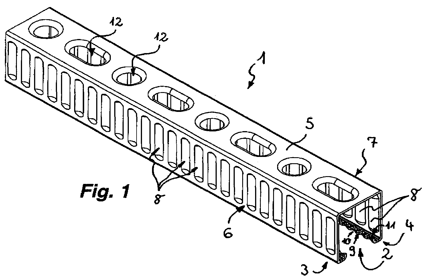
Description
Die Erfindung betrifft eine Montageschiene, die aus einem schienenförmigen Hohlprofil hergestellt und im Verlauf ihrer Schienen-Längserstreckung zumindest eine Schienenöffnung hat, die von den gegenüberliegenden Längsrändern zweier achsparalleler und über eine Schienenrückwand miteinander verbundener Schienenwände begrenzt ist.The invention relates to a mounting rail which has been produced from a rail-shaped hollow profile and in the course of its rail longitudinal extent has at least one rail opening which is delimited by the opposite longitudinal edges of two axially parallel rail walls connected to one another via a rail rear wall.
Man kennt bereits Montageschienen der eingangs erwähnten Art, die aus einem im Querschnitt C-förmigen Hohlprofil hergestellt sind. Die vorbekannten C-Schienen weisen eine meist durchgängige Schienenöffnung auf, in die zur Befestigung einer Rohrschelle oder dergleichen Halteelements zumindest eine Verankerungs- oder Klemmeinheit einsetzbar ist. Dabei wird die Schienenöffnung von den gegenüberliegenden Längsrändern zweier paralleler und über eine Schienenrückwand miteinander verbundener Schienenwände begrenzt, wobei diese Längsränder derart umgebogen und gegebenenfalls auch nach innen aufgekantet sind, dass die Verankerungs- oder Klemmeinheit diese umgebogenen oder aufgekanteten Längsränder zu hintergreifen vermag.Already known mounting rails of the type mentioned, which are made of a cross-sectionally C-shaped hollow profile. The previously known C-rails have a generally continuous rail opening into which at least one anchoring or clamping unit can be used for fastening a pipe clamp or similar holding element. The rail opening is bounded by the opposite longitudinal edges of two parallel and interconnected via a rail rear wall rail walls, said longitudinal edges are bent and possibly also folded inwards so that the anchoring or clamping unit is able to reach behind these bent or aufgekanteten longitudinal edges.
Es ist bereits bekannt, die Kanten der die Schienenöffnung begrenzenden Längsränder in Richtung zur Schienenrückwand umzubiegen und an diesen Kanten zusätzlich auch eine zahnförmige Profilierung vorzusehen, um über die verwendeten Verankerungs- oder Klemmeinheiten höhere Haltekräfte in Schienen-Längsrichtung übertragen zu können. Häufig sind an der Schienenrückwand auch mehrere, als Durchstecköffnung dienende und meist als Rund- oder Langloch ausgebildete Durchbrüche vorgesehen, die zum Beispiel für das Befestigen der Montageschiene an der Decke verwendet werden können. Da diese Durchbrüche gleichzeitig aber auch die Festigkeit und Steifigkeit der Montageschiene reduzieren, wird der die Durchbrüche umgrenzende Randbereich der Schienenrückwand umgeformt oder nach innen aufgekantet, um der Montageschiene in diesem Bereich wieder eine ausreichende Stabilität und Belastbarkeit zu geben.It is already known to bend over the edges of the rail opening delimiting longitudinal edges in the direction of the rail rear wall and additionally provide a tooth-shaped profiling on these edges in order to be able to transmit higher holding forces in rail longitudinal direction via the anchoring or clamping units used. Often, a plurality of apertures serving as an insertion opening and usually formed as a round or oblong hole are also provided on the rail rear wall, which can be used, for example, for fastening the mounting rail to the ceiling. Since these breakthroughs reduce but also the strength and rigidity of the mounting rail, the breakthroughs bounding edge region of the rail rear wall is reformed or folded inwards to give the mounting rail in this area again sufficient stability and resilience.
Es besteht daher insbesondere die Aufgabe, eine Montageschiene zu schaffen, die durch weitere Maßnahmen und Merkmale stets eine ausreichende Stabilität und Belastbarkeit aufweist.There is therefore in particular the task of creating a mounting rail, which always has sufficient stability and resilience by further measures and features.
Die erfindungsgemäße Lösung dieser Aufgabe besteht bei der Montageschiene der eingangs erwähnten Art insbesondere darin, dass in zumindest eine Schienenwand voneinander beabstandete Aussteifungssicken eingeformt sind und/oder dass die die zumindest eine Schienenöffnung begrenzenden Längsränder der Schienenwände nach innen in Richtung zum Hohlprofil-Inneren aufgekantet sind und im Bereich dieser Aufkantungen wellenförmige Aussteifungsaus- und -einformungen tragen.The achievement of this object is in the mounting rail of the type mentioned in particular that in at least one rail wall spaced stiffening beads are formed and / or that the at least one rail opening limiting longitudinal edges of the rail walls are folded inwards towards the hollow profile interior and in the area of these upstands wavy Aussteifungsaus- and -einformungen wear.
Die erfindungsgemäße Montageschiene zeichnet sich durch besondere Merkmale aus, durch welche sich die Steifigkeit und Belastbarkeit dieser Montageschiene zusätzlich erhöhen lässt. Die erfindungsgemäße Montageschiene kann an zumindest einer der beiden Schienenwände und vorzugsweise an beiden Schienenlängswänden voneinander beabstandete Aussteifungssicken aufweisen, die einem Eindrücken der Schienenwände entgegenwirken und deren Belastbarkeit wesentlich erhöhen. Zusätzlich oder stattdessen können die Kanten der die Schienenöffnung begrenzenden Längsränder nach innen in Richtung zur Schienenrückwand aufgekantet sein und im Bereich dieser Aufkantungen wellenförmige Aussteifungsaus- oder -einformungen tragen. Auch die wellenförmigen Aussteifungsaus- oder -einformungen erhöhen die Festigkeit und Stabilität der erfindungsgemäßen Montageschiene. Darüber hinaus können an diesen wellenförmig ein- und ausgeformten Aufkantungen der Längsränder Schraubverbindungen mit einem hohen Anziehdrehmoment realisiert werden. Die erfindungsgemäße Montageschiene kann auch mit einer geringeren Wandstärke hergestellt werden, ohne dass damit gleichzeitig eine verringerte Belastbarkeit der Montageschiene verbunden wäre. Eine mit geringerer Wandstärke hergestellte Montageschiene zeichnet sich gleichzeitig auch durch geringere Materialkosten und ein geringeres Gewicht aus. Auch können die Fertigungskosten reduziert werden, da sich dünneres Material leichter zu einer Montageschiene umformen lässt. Die erfindungsgemäße Montageschiene ist daher auch kostengünstig herstellbar.The mounting rail according to the invention is characterized by special features by which the stiffness and Load capacity of this mounting rail can increase additionally. The mounting rail according to the invention may have on at least one of the two rail walls and preferably on both rails longitudinal walls spaced stiffening beads, which counteract a depression of the rail walls and significantly increase their capacity. In addition or instead, the edges of the longitudinal opening delimiting the rail opening can be folded inwards in the direction of the rail rear wall and carry wavy stiffening outs or recesses in the region of these raised edges. The wavy Aussteifungsaus- or -einformungen increase the strength and stability of the mounting rail according to the invention. In addition, screw connections with a high tightening torque can be realized at these wavy shaped and formed upturns of the longitudinal edges. The mounting rail according to the invention can also be produced with a smaller wall thickness, without that at the same time a reduced load capacity of the mounting rail would be connected. A mounting rail made with a lower wall thickness is also characterized by lower material costs and a lower weight. Also, the manufacturing cost can be reduced because thinner material can be easier to reshape a mounting rail. The mounting rail according to the invention is therefore also inexpensive to produce.
Um auf die erfindungsgemäße Montageschiene hohe Haltekräfte auch in Schienen-Längsrichtung übertragen zu können, ist es vorteilhaft, wenn zumindest einer der Längsränder an seinem nach innen gerichteten Schmalrand eine zahn- oder wellenförmige Profilierung trägt.In order to be able to transfer high holding forces to the mounting rail according to the invention also in the longitudinal direction of the rail, it is advantageous if at least one of the longitudinal edges carries a tooth-shaped or wavy profiling on its inwardly directed narrow edge.
Selbst eine aus dünnem Material hergestellte Montageschiene zeichnet sich durch eine besonders hohe Steifigkeit gegen Durchbiegungen aus, wenn die Aussteifungssicken quer und vorzugsweise rechtwinklig zur Schienen-Längserstreckung orientiert sind und/oder wenn die Aussteifungssicken jeweils als Wand-Einformungen ausgebildet sind.Even a mounting rail made of thin material is characterized by a particularly high rigidity Deflections from when the stiffening beads are oriented transversely and preferably at right angles to the rail longitudinal extent and / or if the stiffening beads are each formed as wall recesses.
Mit Hilfe der erfindungsgemäßen Montageschienen lassen sich auch Traversen, Wandkonsolen und Tragrahmen einfach und fachgerecht vormontieren oder auf der Baustelle herstellen. Um die erfindungsgemäße Montageschiene beispielsweise an einer Wand oder einer Decke befestigen zu können, ist es vorteilhaft, wenn in der Schienenrückwand zumindest eine Durchstecköffnung vorgesehen ist.With the help of mounting rails according to the invention also trusses, wall brackets and support frame can be easily and professionally preassembled or produced on site. In order to attach the mounting rail according to the invention, for example, to a wall or a ceiling, it is advantageous if at least one through opening is provided in the rail rear wall.
Um die mit jedem Durchbruch des Schienenprofils verbundene Schwächung der Montageschiene zumindest ausgleichen zu können, ist es vorteilhaft, wenn der eine Durchstecköffnung umgrenzende Randbereich der Schienenrückwand nach innen in Richtung zum Hohlprofil-Inneren aufgekantet ist.In order to at least be able to compensate for the weakening of the mounting rail associated with each breakthrough of the rail profile, it is advantageous if the edge region of the rail rear wall bounding an insertion opening is folded inwards in the direction of the hollow profile interior.
Weitere Merkmale der Erfindung ergeben sich aus der folgenden Beschreibung eines erfindungsgemäßen Ausführungsbeispieles in Verbindung mit den Ansprüchen sowie der Zeichnung. Die einzelnen Merkmale können je für sich oder zu mehreren bei einer Ausführungsform gemäß der Erfindung verwirklicht sein.Further features of the invention will become apparent from the following description of an embodiment of the invention in conjunction with the claims and the drawings. The individual features may be implemented individually or in combination in an embodiment according to the invention.
Es zeigt:
- Fig. 1
- eine Montageschiene in einer perspektivischen Darstellung,
- Fig. 2
- die Montageschiene aus
Figur 1 - Fig. 3
- die Montageschiene aus
Figur 12 in einer Stirnansicht und - Fig. 4
- die Montageschiene aus
Figur 1 bis 3
- Fig. 1
- a mounting rail in a perspective view,
- Fig. 2
- the mounting rail off
FIG. 1 in a perspective detail in one of its end edge areas, - Fig. 3
- the mounting rail off
FIG. 1 and2 in a front view and - Fig. 4
- the mounting rail off
Figure 1 to 3 in a top view.
In den
In den
Aus den
In
Mit Hilfe der Montageschiene 1 lassen sich auch Traversen, Wandkonsolen und Tragrahmen einfach und fachgerecht vormontieren oder auf der Baustelle herstellen. Um die Montageschiene 1 beispielsweise an einer Wand oder einer Decke befestigen zu können, sind in der Schienenrückwand 5 mehrere, als Durchbrüche ausgebildete Durchstecköffnungen 12 vorgesehen. Diese Durchstecköffnungen 12 sind wechselweise als Rundlöcher und als Langlöcher ausgebildet. Dabei ist der eine Durchstecköffnung 12 umgrenzende Randbereich der Schienenrückwand 5 nach innen in Richtung zum Hohlprofil-Inneren aufgekantet, um die mit diesen Durchbrüchen verbundene Schwächung der Montageschiene 1 zumindest auszugleichen und um eine hohe Stabilität und Belastbarkeit der Montageschiene auch in diesem Bereich zu begünstigen.With the help of the mounting
Die hier dargestellte Montageschiene 1 kann auch mit einer geringeren Wandstärke hergestellt werden, ohne dass damit gleichzeitig eine verringerte Belastbarkeit der Montageschiene 1 verbunden wäre. Wird die Montageschiene 1 mit einer geringeren Wandstärke hergestellt, lassen sich die Materialkosten und das Gewicht der Montageschiene 1 reduzieren. Auch können die Fertigungskosten vermindert werden, da sich dünneres Material leichter zu einer Montageschiene 1 umformen lässt. Die hier dargestellte Montageschiene 1 ist daher auch kostengünstig herstellbar.The
Claims (6)
Applications Claiming Priority (1)
| Application Number | Priority Date | Filing Date | Title |
|---|---|---|---|
| DE102007028342A DE102007028342A1 (en) | 2007-06-20 | 2007-06-20 | mounting rail |
Publications (3)
| Publication Number | Publication Date |
|---|---|
| EP2006460A2 true EP2006460A2 (en) | 2008-12-24 |
| EP2006460A3 EP2006460A3 (en) | 2009-11-04 |
| EP2006460B1 EP2006460B1 (en) | 2011-12-21 |
Family
ID=39718281
Family Applications (1)
| Application Number | Title | Priority Date | Filing Date |
|---|---|---|---|
| EP08010898A Not-in-force EP2006460B1 (en) | 2007-06-20 | 2008-06-16 | Mounting rail |
Country Status (3)
| Country | Link |
|---|---|
| EP (1) | EP2006460B1 (en) |
| AT (1) | ATE538263T1 (en) |
| DE (1) | DE102007028342A1 (en) |
Cited By (2)
| Publication number | Priority date | Publication date | Assignee | Title |
|---|---|---|---|---|
| DE102012014790A1 (en) | 2012-07-25 | 2014-02-13 | Welser Profile Austria Gmbh | Assembly rail for installation of suspended ceilings or for attaching tubes, has metal profile with opening side for fastening engaged mounting elements, where profile has another opening side, at which opening slit is formed |
| EP2827043A1 (en) * | 2013-07-18 | 2015-01-21 | Welser Profile Austria GmbH | Method for producing a twin rail and twin rail |
Families Citing this family (1)
| Publication number | Priority date | Publication date | Assignee | Title |
|---|---|---|---|---|
| DE102014016617A1 (en) | 2014-11-11 | 2016-05-12 | Fischerwerke Gmbh & Co. Kg | mounting rail |
Family Cites Families (6)
| Publication number | Priority date | Publication date | Assignee | Title |
|---|---|---|---|---|
| SE394478B (en) * | 1974-10-16 | 1977-06-27 | Interoc Fasad Ab | PROFILE RAIL OF THIN PLATE FOR USE AS A DISTANCE, STRENGTHENING AND LOAD-TAKING CONSTRUCTION ELEMENTS IN HEAT-INSULATED BUILDING PARTS |
| US5687538A (en) * | 1995-02-14 | 1997-11-18 | Super Stud Building Products, Inc. | Floor joist with built-in truss-like stiffner |
| DE19612275C2 (en) * | 1996-03-28 | 1999-04-15 | Hilti Ag | Mounting rail |
| DE19652027C2 (en) * | 1996-12-13 | 2001-05-17 | Diag Design Ag Zug | Mounting rail for fastening pipes or the like |
| DE19934310A1 (en) * | 1999-07-21 | 2001-01-25 | Profil Vertrieb Gmbh | Stand profile designed as a lightweight profile |
| EP1124023A3 (en) * | 2000-01-14 | 2001-10-17 | Richter-System GmbH & Co. KG | C-shaped section for partition walls |
-
2007
- 2007-06-20 DE DE102007028342A patent/DE102007028342A1/en not_active Withdrawn
-
2008
- 2008-06-16 EP EP08010898A patent/EP2006460B1/en not_active Not-in-force
- 2008-06-16 AT AT08010898T patent/ATE538263T1/en active
Cited By (2)
| Publication number | Priority date | Publication date | Assignee | Title |
|---|---|---|---|---|
| DE102012014790A1 (en) | 2012-07-25 | 2014-02-13 | Welser Profile Austria Gmbh | Assembly rail for installation of suspended ceilings or for attaching tubes, has metal profile with opening side for fastening engaged mounting elements, where profile has another opening side, at which opening slit is formed |
| EP2827043A1 (en) * | 2013-07-18 | 2015-01-21 | Welser Profile Austria GmbH | Method for producing a twin rail and twin rail |
Also Published As
| Publication number | Publication date |
|---|---|
| ATE538263T1 (en) | 2012-01-15 |
| EP2006460A3 (en) | 2009-11-04 |
| EP2006460B1 (en) | 2011-12-21 |
| DE102007028342A1 (en) | 2008-12-24 |
Similar Documents
| Publication | Publication Date | Title |
|---|---|---|
| DE19720016C2 (en) | Curtain wall construction | |
| DE112016000650B4 (en) | BODY STRUCTURE OF A VEHICLE | |
| EP2944737B1 (en) | Clamping device for connecting section bars | |
| DE20307769U1 (en) | joist hanger | |
| CH636394A5 (en) | PANEL DESIGN. | |
| DE202007001781U1 (en) | drawer | |
| EP0148286A1 (en) | Flanged joint | |
| DE202009009407U1 (en) | Floor profile arrangement | |
| EP0901549B1 (en) | Wall support for facade substructures | |
| EP3574164B1 (en) | Support for fastening façade elements | |
| EP2686501B1 (en) | Component assembly and suspension device for supporting rails and method for producing same | |
| DE102008030602A1 (en) | Scaffolding with lifting device for padding units | |
| DE202007008611U1 (en) | Mounting rail for use in building site, has reinforcement flanges molded in one of rail walls, and arranged at distance from each other and/or longitudinal edges, which are flanged inward and support shaft-shaped reinforcement moldings | |
| EP0312646A2 (en) | Middle beam for window frames | |
| DE102005019977B4 (en) | Facade system made of ceramic façade panels for use as a ventilated façade on a supporting building wall | |
| EP2006460B1 (en) | Mounting rail | |
| DE3729824C2 (en) | ||
| DE60028902T2 (en) | LENGTH SUPPORT FOR A METAL SCAFFOLD, ESPECIALLY FOR A FRAME OF A CONTROL CABINET | |
| EP3527734B1 (en) | Drainage channel with attached frame | |
| AT13864U1 (en) | Supporting device for a concrete formwork | |
| EP3527744B1 (en) | Basis profile of a floor profile arrangement | |
| AT401854B (en) | DRAWER | |
| EP2404011A1 (en) | Device for attaching facade elements and facade element | |
| DE202011108692U1 (en) | Hollow profile and hall frame with such a profile | |
| AT509393B1 (en) | WALL SUPPORT |
Legal Events
| Date | Code | Title | Description |
|---|---|---|---|
| PUAI | Public reference made under article 153(3) epc to a published international application that has entered the european phase |
Free format text: ORIGINAL CODE: 0009012 |
|
| AK | Designated contracting states |
Kind code of ref document: A2 Designated state(s): AT BE BG CH CY CZ DE DK EE ES FI FR GB GR HR HU IE IS IT LI LT LU LV MC MT NL NO PL PT RO SE SI SK TR |
|
| AX | Request for extension of the european patent |
Extension state: AL BA MK RS |
|
| RAP1 | Party data changed (applicant data changed or rights of an application transferred) |
Owner name: SIKLA HOLDINGS GMBH |
|
| PUAL | Search report despatched |
Free format text: ORIGINAL CODE: 0009013 |
|
| AK | Designated contracting states |
Kind code of ref document: A3 Designated state(s): AT BE BG CH CY CZ DE DK EE ES FI FR GB GR HR HU IE IS IT LI LT LU LV MC MT NL NO PL PT RO SE SI SK TR |
|
| AX | Request for extension of the european patent |
Extension state: AL BA MK RS |
|
| 17P | Request for examination filed |
Effective date: 20100303 |
|
| AKX | Designation fees paid |
Designated state(s): AT BE BG CH CY LI |
|
| RBV | Designated contracting states (corrected) |
Designated state(s): AT BE DE FR GB |
|
| REG | Reference to a national code |
Ref country code: DE Ref legal event code: 8566 |
|
| 17Q | First examination report despatched |
Effective date: 20100826 |
|
| GRAP | Despatch of communication of intention to grant a patent |
Free format text: ORIGINAL CODE: EPIDOSNIGR1 |
|
| RIN1 | Information on inventor provided before grant (corrected) |
Inventor name: WARKUS, CLEMENS |
|
| GRAS | Grant fee paid |
Free format text: ORIGINAL CODE: EPIDOSNIGR3 |
|
| GRAA | (expected) grant |
Free format text: ORIGINAL CODE: 0009210 |
|
| AK | Designated contracting states |
Kind code of ref document: B1 Designated state(s): AT BE DE FR GB |
|
| REG | Reference to a national code |
Ref country code: GB Ref legal event code: FG4D Free format text: NOT ENGLISH |
|
| REG | Reference to a national code |
Ref country code: AT Ref legal event code: REF Ref document number: 538263 Country of ref document: AT Kind code of ref document: T Effective date: 20120115 |
|
| REG | Reference to a national code |
Ref country code: DE Ref legal event code: R096 Ref document number: 502008005903 Country of ref document: DE Effective date: 20120301 |
|
| PLBE | No opposition filed within time limit |
Free format text: ORIGINAL CODE: 0009261 |
|
| STAA | Information on the status of an ep patent application or granted ep patent |
Free format text: STATUS: NO OPPOSITION FILED WITHIN TIME LIMIT |
|
| 26N | No opposition filed |
Effective date: 20120924 |
|
| BERE | Be: lapsed |
Owner name: SIKLA HOLDING GMBH Effective date: 20120630 |
|
| REG | Reference to a national code |
Ref country code: DE Ref legal event code: R097 Ref document number: 502008005903 Country of ref document: DE Effective date: 20120924 |
|
| PG25 | Lapsed in a contracting state [announced via postgrant information from national office to epo] |
Ref country code: BE Free format text: LAPSE BECAUSE OF NON-PAYMENT OF DUE FEES Effective date: 20120630 |
|
| REG | Reference to a national code |
Ref country code: FR Ref legal event code: PLFP Year of fee payment: 9 |
|
| REG | Reference to a national code |
Ref country code: FR Ref legal event code: PLFP Year of fee payment: 10 |
|
| PGFP | Annual fee paid to national office [announced via postgrant information from national office to epo] |
Ref country code: FR Payment date: 20170621 Year of fee payment: 10 Ref country code: GB Payment date: 20170626 Year of fee payment: 10 |
|
| PGFP | Annual fee paid to national office [announced via postgrant information from national office to epo] |
Ref country code: AT Payment date: 20170620 Year of fee payment: 10 |
|
| REG | Reference to a national code |
Ref country code: AT Ref legal event code: MM01 Ref document number: 538263 Country of ref document: AT Kind code of ref document: T Effective date: 20180616 |
|
| GBPC | Gb: european patent ceased through non-payment of renewal fee |
Effective date: 20180616 |
|
| PG25 | Lapsed in a contracting state [announced via postgrant information from national office to epo] |
Ref country code: GB Free format text: LAPSE BECAUSE OF NON-PAYMENT OF DUE FEES Effective date: 20180616 Ref country code: AT Free format text: LAPSE BECAUSE OF NON-PAYMENT OF DUE FEES Effective date: 20180616 Ref country code: FR Free format text: LAPSE BECAUSE OF NON-PAYMENT OF DUE FEES Effective date: 20180630 |
|
| PGFP | Annual fee paid to national office [announced via postgrant information from national office to epo] |
Ref country code: DE Payment date: 20240603 Year of fee payment: 17 |
|
| REG | Reference to a national code |
Ref country code: DE Ref legal event code: R119 Ref document number: 502008005903 Country of ref document: DE |
|
| PG25 | Lapsed in a contracting state [announced via postgrant information from national office to epo] |
Ref country code: DE Free format text: LAPSE BECAUSE OF NON-PAYMENT OF DUE FEES Effective date: 20260101 |