EP2006460B1 - Rail de montage - Google Patents
Rail de montage Download PDFInfo
- Publication number
- EP2006460B1 EP2006460B1 EP08010898A EP08010898A EP2006460B1 EP 2006460 B1 EP2006460 B1 EP 2006460B1 EP 08010898 A EP08010898 A EP 08010898A EP 08010898 A EP08010898 A EP 08010898A EP 2006460 B1 EP2006460 B1 EP 2006460B1
- Authority
- EP
- European Patent Office
- Prior art keywords
- rail
- mounting rail
- mounting
- opening
- profile
- Prior art date
- Legal status (The legal status is an assumption and is not a legal conclusion. Google has not performed a legal analysis and makes no representation as to the accuracy of the status listed.)
- Not-in-force
Links
Images


Classifications
-
- E—FIXED CONSTRUCTIONS
- E04—BUILDING
- E04C—STRUCTURAL ELEMENTS; BUILDING MATERIALS
- E04C3/00—Structural elongated elements designed for load-supporting
- E04C3/02—Joists; Girders, trusses, or trusslike structures, e.g. prefabricated; Lintels; Transoms; Braces
- E04C3/04—Joists; Girders, trusses, or trusslike structures, e.g. prefabricated; Lintels; Transoms; Braces of metal
- E04C3/08—Joists; Girders, trusses, or trusslike structures, e.g. prefabricated; Lintels; Transoms; Braces of metal with apertured web, e.g. with a web consisting of bar-like components; Honeycomb girders
- E04C3/09—Joists; Girders, trusses, or trusslike structures, e.g. prefabricated; Lintels; Transoms; Braces of metal with apertured web, e.g. with a web consisting of bar-like components; Honeycomb girders at least partly of bent or otherwise deformed strip- or sheet-like material
-
- E—FIXED CONSTRUCTIONS
- E04—BUILDING
- E04B—GENERAL BUILDING CONSTRUCTIONS; WALLS, e.g. PARTITIONS; ROOFS; FLOORS; CEILINGS; INSULATION OR OTHER PROTECTION OF BUILDINGS
- E04B9/00—Ceilings; Construction of ceilings, e.g. false ceilings; Ceiling construction with regard to insulation
- E04B9/18—Means for suspending the supporting construction
-
- E—FIXED CONSTRUCTIONS
- E04—BUILDING
- E04C—STRUCTURAL ELEMENTS; BUILDING MATERIALS
- E04C3/00—Structural elongated elements designed for load-supporting
- E04C3/02—Joists; Girders, trusses, or trusslike structures, e.g. prefabricated; Lintels; Transoms; Braces
- E04C3/04—Joists; Girders, trusses, or trusslike structures, e.g. prefabricated; Lintels; Transoms; Braces of metal
- E04C2003/0404—Joists; Girders, trusses, or trusslike structures, e.g. prefabricated; Lintels; Transoms; Braces of metal beams, girders, or joists characterised by cross-sectional aspects
- E04C2003/0443—Joists; Girders, trusses, or trusslike structures, e.g. prefabricated; Lintels; Transoms; Braces of metal beams, girders, or joists characterised by cross-sectional aspects characterised by substantial shape of the cross-section
- E04C2003/0473—U- or C-shaped
Definitions
- the invention relates to a mounting rail, which has been produced from a rail-shaped hollow profile and in the course of their rail length has at least one rail opening which is bounded by the opposite longitudinal edges of two axially parallel and interconnected via a rail rear wall rail walls, wherein the at least one rail opening limiting longitudinal edges of Rail walls are tilted inwards in the direction of the hollow profile inside and carry wavy stiffening formations in the area of this Aufkantache.
- DE-A-99 34 310 From the DE-A-99 34 310 already known as a lightweight profile trained stand profile, which has two profile legs, which extend in the profile longitudinal direction at a distance from each other and are interconnected by a profile web. While, may have a profile extending in the profile longitudinal direction having profile web on a building wall, are facing away from the profile web. Longitudinal edges of the profile legs provided inwardly projecting and directed edge flanges, with which the prior art uprights profile can be fixed on the building side, which is to be accommodated in the profile interior rock wool or another insulating material protected.
- the end DE-A-199 34 310 However, prior art stand profile is not a mounting rail, which would be intended for the installation of pipe clamps or other fasteners.
- the prior art stud profile in particular has no rail opening which is intended to receive an anchoring unit or another fastening means. As far as a few Versteitungssicken are provided on the known stand profile, they should give the stator profile only sufficient inherent stability
- the longitudinal edges of the rail walls delimiting the at least one rail opening are bent inward in the direction of the hollow profile interior.
- delimiting longitudinal edges holding projections are provided which engage behind the support member of an anchoring unit. Since the supporting part of the anchoring unit has a counter profiling on its flat side which acts on the narrow edges, the supporting part engaging on the longitudinal edges is held securely and firmly in its position on the mounting rail.
- the mounting rail according to the invention is characterized by special features by which the rigidity and load capacity of this mounting rail can be additionally increased.
- the edges of the rail opening delimiting longitudinal edges are folded inward in the direction of the rail rear wall and carry in the region of this Aufkantitch wavy Aussteifungsaus- and -einformungen.
- the wavy Aussteifungsaus- or -einformungen increase the strength and stability of the mounting rail according to the invention.
- the longitudinal edges screw connections can be realized with a high tightening torque.
- the mounting rail according to the invention can also be produced with a smaller wall thickness, without that at the same time a reduced load capacity of the mounting rail would be connected.
- a mounting rail made with a smaller wall thickness is also characterized by lower material costs and a lower weight. Also, the manufacturing cost can be reduced because thinner material can be easier to reshape a mounting rail.
- the mounting rail according to the invention is therefore also inexpensive to produce.
- At least one of the longitudinal edges carries a tooth-shaped or wavy profiling on its inwardly directed narrow edge.
- stiffening beads Deflections from when the stiffening beads are oriented transversely and preferably at right angles to the rail longitudinal extent and / or if the stiffening beads are each formed as wall recesses.
- mounting rails according to the invention also trusses, wall brackets and support frame can be easily and professionally preassembled or produced on site.
- the mounting rail according to the invention for example, to a wall or a ceiling, it is advantageous if at least one through opening is provided in the rail rear wall.
- edge region of the rail rear wall bounding an insertion opening is folded inwards in the direction of the hollow profile interior.
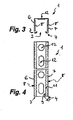
- a mounting rail 1 is shown, which is made of a rail-shaped hollow profile.
- the mounting rail 1 here has a running over the entire rail longitudinal extension rail opening 2, which is bounded by the opposite longitudinal edges 3, 4 of two axially parallel and a rail rear wall 5 interconnected rail walls 6, 7. It is also possible that the mounting rail 1 instead of a continuous rail opening 2 has several, for example formed as round or oblong holes rail openings.
- anchoring or clamping unit can be used in the at least one rail opening 2.
- stiffening beads 8 are formed, which are oriented here at right angles to the rail longitudinal extent and designed as wall recesses. These stiffening beads 8, which are arranged at equal distances from each other and extend over almost the entire transverse extent or height of the rail walls 6, 7, counteract deflections of the mounting rail 1 and increase the rigidity and resilience of the mounting rail 1 substantially.
- FIG. 2 It is shown that the longitudinal edges 3, 4 carry at their inwardly directed narrow edges a tooth-shaped or wavy profiling 11. By this tooth or wave-shaped profiling 11 higher forces can also be transmitted in 'rail longitudinal direction of an anchoring or clamping unit on the mounting rail 1.
- wall brackets and support frame can be easily and professionally pre-assembled or produced on site.
- the mounting rail 1 for example, to a wall or ceiling
- a plurality of through holes 12 formed as openings provided in the rail rear wall 5 are formed alternately as round holes and slots.
- an insertion opening 12 bounding edge region of the rail rear wall 5 is folded inward towards the hollow profile interior to at least compensate for the weakening of the mounting rail 1 associated with these breakthroughs and to favor a high stability and resilience of the mounting rail in this area.
- the mounting rail 1 shown here can also be produced with a smaller wall thickness without it At the same time a reduced load capacity of the mounting rail 1 would be connected. If the mounting rail 1 is produced with a smaller wall thickness, the material costs and the weight of the mounting rail 1 can be reduced. Also, the manufacturing cost can be reduced because thinner material can be easier to reshape to a mounting rail 1. The mounting rail 1 shown here is therefore also inexpensive to produce.
Landscapes
- Engineering & Computer Science (AREA)
- Architecture (AREA)
- Civil Engineering (AREA)
- Structural Engineering (AREA)
- Physics & Mathematics (AREA)
- Electromagnetism (AREA)
- Mutual Connection Of Rods And Tubes (AREA)
- Drawers Of Furniture (AREA)
- Supports For Pipes And Cables (AREA)
- Rod-Shaped Construction Members (AREA)
Claims (7)
- Rail de montage (1), qui est fabriqué à partir d'un profilé creux en forme de rail et qui possède dans le cours de son étendue longitudinale de rail au moins une ouverture de rail (2), ouverture (2) qui est délimitée par les bords longitudinaux opposés (3, 4) de deux parois de rail (6, 7) axialement parallèles et mutuellement reliées par une paroi arrière de rail (5), sachant que les bords longitudinaux (3, 4), délimitant l'ouverture de rail au moins unique (2), des parois de rail (6, 7) sont relevés vers l'intérieur en direction de l'intérieur du profilé creux et portent, dans la région de ces parties relevées, des formations de renforcement de forme ondulée, caractérisé en ce que les formations de renforcement de forme ondulée sont réalisées sous la forme de formations de renforcement en relief et en creux (9, 10).
- Rail de montage selon la revendication 1, caractérisé en ce que des moulures de renforcement (8) distantes les unes des autres sont formées dans au moins une des parois de rail (6, 7).
- Rail de montage selon la revendication 1 ou 2, caractérisé en ce qu'au moins un des bords longitudinaux (3, 4) porte, sur son bord étroit dirigé vers l'intérieur, un profilage (11) en forme de dent ou d'ondulation.
- Rail de montage selon l'une des revendications 1 à 3, caractérisé en ce que les moulures de renforcement (8) sont orientées transversalement et de préférence perpendiculairement à l'étendue longitudinale du rail.
- Rail de montage selon l'une des revendications 1 à 4, caractérisé en ce que les moulures de renforcement (8) sont respectivement réalisées sous la forme de formations de paroi en creux.
- Rail de montage selon l'une des revendications 1 à 5, caractérisé en ce qu'au moins une ouverture traversante (12) est prévue dans la paroi arrière de rail (5).
- Rail de montage selon la revendication 6, caractérisé en ce que la région de bord de la paroi arrière de rail (5) qui circonscrit une ouverture traversante (12) est relevée vers l'intérieur en direction de l'intérieur du profilé creux.
Applications Claiming Priority (1)
| Application Number | Priority Date | Filing Date | Title |
|---|---|---|---|
| DE102007028342A DE102007028342A1 (de) | 2007-06-20 | 2007-06-20 | Montageschiene |
Publications (3)
| Publication Number | Publication Date |
|---|---|
| EP2006460A2 EP2006460A2 (fr) | 2008-12-24 |
| EP2006460A3 EP2006460A3 (fr) | 2009-11-04 |
| EP2006460B1 true EP2006460B1 (fr) | 2011-12-21 |
Family
ID=39718281
Family Applications (1)
| Application Number | Title | Priority Date | Filing Date |
|---|---|---|---|
| EP08010898A Not-in-force EP2006460B1 (fr) | 2007-06-20 | 2008-06-16 | Rail de montage |
Country Status (3)
| Country | Link |
|---|---|
| EP (1) | EP2006460B1 (fr) |
| AT (1) | ATE538263T1 (fr) |
| DE (1) | DE102007028342A1 (fr) |
Families Citing this family (3)
| Publication number | Priority date | Publication date | Assignee | Title |
|---|---|---|---|---|
| DE102012014790A1 (de) | 2012-07-25 | 2014-02-13 | Welser Profile Austria Gmbh | Montageschiene sowie Verfahren zu deren Herstellung |
| DE102013011966A1 (de) * | 2013-07-18 | 2015-01-22 | Welser Profile Austria Gmbh | Verfahren zur Herstellung einer Doppelschiene sowie Doppelschiene |
| DE102014016617A1 (de) | 2014-11-11 | 2016-05-12 | Fischerwerke Gmbh & Co. Kg | Montageschiene |
Family Cites Families (6)
| Publication number | Priority date | Publication date | Assignee | Title |
|---|---|---|---|---|
| SE394478B (sv) * | 1974-10-16 | 1977-06-27 | Interoc Fasad Ab | Profilskena av tunnplat for anvendning sasom distanshallande, forstyvande och belastningsupptagande konstruktionselement i vermeisolerade byggnadsdelar |
| US5687538A (en) * | 1995-02-14 | 1997-11-18 | Super Stud Building Products, Inc. | Floor joist with built-in truss-like stiffner |
| DE19612275C2 (de) * | 1996-03-28 | 1999-04-15 | Hilti Ag | Montageschiene |
| DE19652027C2 (de) * | 1996-12-13 | 2001-05-17 | Diag Design Ag Zug | Montageschiene zur Befestigung von Rohren o. dgl. Gegenständen |
| DE19934310A1 (de) * | 1999-07-21 | 2001-01-25 | Profil Vertrieb Gmbh | Als Leichtbauprofil ausgebildetes Ständerprofil |
| EP1124023A3 (fr) * | 2000-01-14 | 2001-10-17 | Richter-System GmbH & Co. KG | Profilé en forme de C pour cloisons |
-
2007
- 2007-06-20 DE DE102007028342A patent/DE102007028342A1/de not_active Withdrawn
-
2008
- 2008-06-16 AT AT08010898T patent/ATE538263T1/de active
- 2008-06-16 EP EP08010898A patent/EP2006460B1/fr not_active Not-in-force
Also Published As
| Publication number | Publication date |
|---|---|
| ATE538263T1 (de) | 2012-01-15 |
| DE102007028342A1 (de) | 2008-12-24 |
| EP2006460A3 (fr) | 2009-11-04 |
| EP2006460A2 (fr) | 2008-12-24 |
Similar Documents
| Publication | Publication Date | Title |
|---|---|---|
| EP1074671B1 (fr) | Poteau profilé configuré en tant que profilé pour cloison légère | |
| EP2944737B1 (fr) | Dispositif de serrage destiné à relier des éléments profilés | |
| DE102005029738A1 (de) | Energieabsorberelement und dieses verwendende Kraftfahrzeugkarosserie | |
| DE3606112A1 (de) | Tragschiene fuer unterdecken und zubehoer | |
| DE20307769U1 (de) | Balkenschuh | |
| EP2006460B1 (fr) | Rail de montage | |
| EP2686501B1 (fr) | Module à assembler ainsi que dispositif de suspension pour rails de support et leurs procédés de fabrication. | |
| EP2369082B1 (fr) | Système de liaison de deux profilés en C croisés | |
| DE102017101509A1 (de) | Konsole zur Befestigung von Fassadenelementen | |
| DE202007008611U1 (de) | Montageschiene | |
| EP0364768B1 (fr) | Elément de cloison de séparation | |
| EP1866492B1 (fr) | Profile en c et cloison de séparation à profile en c | |
| CH639165A5 (en) | Panel element with a sound-insulating mat, in particular for soundproofing walls, soundproofing floors and soundproofing booths | |
| AT401854B (de) | Schublade | |
| EP3910125B1 (fr) | Bâti de support permettant de suspendre au moins un absorbeur de son provenant du plafond, système d'amélioration de l'acoustique dans une pièce | |
| DE19950890C1 (de) | Ständerprofilstab zur Errichtung von Trockenbauwänden | |
| EP3730718B1 (fr) | Dispositif de façade | |
| EP2453066A2 (fr) | Profilé de support réglable en longueur pour paroi de construction légère | |
| EP2241697B1 (fr) | Base de soutien | |
| AT511324B1 (de) | Rohr | |
| EP2476810A1 (fr) | Profil de doublement | |
| DE102012014790A1 (de) | Montageschiene sowie Verfahren zu deren Herstellung | |
| DE102005033037B3 (de) | Stegdecke | |
| EP1878842B1 (fr) | Habillage constitué de tiges pour des plafonds, des murs ou des éléments de construction analogues | |
| WO1986000950A1 (fr) | Dispositif pour retenir la neige |
Legal Events
| Date | Code | Title | Description |
|---|---|---|---|
| PUAI | Public reference made under article 153(3) epc to a published international application that has entered the european phase |
Free format text: ORIGINAL CODE: 0009012 |
|
| AK | Designated contracting states |
Kind code of ref document: A2 Designated state(s): AT BE BG CH CY CZ DE DK EE ES FI FR GB GR HR HU IE IS IT LI LT LU LV MC MT NL NO PL PT RO SE SI SK TR |
|
| AX | Request for extension of the european patent |
Extension state: AL BA MK RS |
|
| RAP1 | Party data changed (applicant data changed or rights of an application transferred) |
Owner name: SIKLA HOLDINGS GMBH |
|
| PUAL | Search report despatched |
Free format text: ORIGINAL CODE: 0009013 |
|
| AK | Designated contracting states |
Kind code of ref document: A3 Designated state(s): AT BE BG CH CY CZ DE DK EE ES FI FR GB GR HR HU IE IS IT LI LT LU LV MC MT NL NO PL PT RO SE SI SK TR |
|
| AX | Request for extension of the european patent |
Extension state: AL BA MK RS |
|
| 17P | Request for examination filed |
Effective date: 20100303 |
|
| AKX | Designation fees paid |
Designated state(s): AT BE BG CH CY LI |
|
| RBV | Designated contracting states (corrected) |
Designated state(s): AT BE DE FR GB |
|
| REG | Reference to a national code |
Ref country code: DE Ref legal event code: 8566 |
|
| 17Q | First examination report despatched |
Effective date: 20100826 |
|
| GRAP | Despatch of communication of intention to grant a patent |
Free format text: ORIGINAL CODE: EPIDOSNIGR1 |
|
| RIN1 | Information on inventor provided before grant (corrected) |
Inventor name: WARKUS, CLEMENS |
|
| GRAS | Grant fee paid |
Free format text: ORIGINAL CODE: EPIDOSNIGR3 |
|
| GRAA | (expected) grant |
Free format text: ORIGINAL CODE: 0009210 |
|
| AK | Designated contracting states |
Kind code of ref document: B1 Designated state(s): AT BE DE FR GB |
|
| REG | Reference to a national code |
Ref country code: GB Ref legal event code: FG4D Free format text: NOT ENGLISH |
|
| REG | Reference to a national code |
Ref country code: AT Ref legal event code: REF Ref document number: 538263 Country of ref document: AT Kind code of ref document: T Effective date: 20120115 |
|
| REG | Reference to a national code |
Ref country code: DE Ref legal event code: R096 Ref document number: 502008005903 Country of ref document: DE Effective date: 20120301 |
|
| PLBE | No opposition filed within time limit |
Free format text: ORIGINAL CODE: 0009261 |
|
| STAA | Information on the status of an ep patent application or granted ep patent |
Free format text: STATUS: NO OPPOSITION FILED WITHIN TIME LIMIT |
|
| 26N | No opposition filed |
Effective date: 20120924 |
|
| BERE | Be: lapsed |
Owner name: SIKLA HOLDING GMBH Effective date: 20120630 |
|
| REG | Reference to a national code |
Ref country code: DE Ref legal event code: R097 Ref document number: 502008005903 Country of ref document: DE Effective date: 20120924 |
|
| PG25 | Lapsed in a contracting state [announced via postgrant information from national office to epo] |
Ref country code: BE Free format text: LAPSE BECAUSE OF NON-PAYMENT OF DUE FEES Effective date: 20120630 |
|
| REG | Reference to a national code |
Ref country code: FR Ref legal event code: PLFP Year of fee payment: 9 |
|
| REG | Reference to a national code |
Ref country code: FR Ref legal event code: PLFP Year of fee payment: 10 |
|
| PGFP | Annual fee paid to national office [announced via postgrant information from national office to epo] |
Ref country code: FR Payment date: 20170621 Year of fee payment: 10 Ref country code: GB Payment date: 20170626 Year of fee payment: 10 |
|
| PGFP | Annual fee paid to national office [announced via postgrant information from national office to epo] |
Ref country code: AT Payment date: 20170620 Year of fee payment: 10 |
|
| REG | Reference to a national code |
Ref country code: AT Ref legal event code: MM01 Ref document number: 538263 Country of ref document: AT Kind code of ref document: T Effective date: 20180616 |
|
| GBPC | Gb: european patent ceased through non-payment of renewal fee |
Effective date: 20180616 |
|
| PG25 | Lapsed in a contracting state [announced via postgrant information from national office to epo] |
Ref country code: GB Free format text: LAPSE BECAUSE OF NON-PAYMENT OF DUE FEES Effective date: 20180616 Ref country code: AT Free format text: LAPSE BECAUSE OF NON-PAYMENT OF DUE FEES Effective date: 20180616 Ref country code: FR Free format text: LAPSE BECAUSE OF NON-PAYMENT OF DUE FEES Effective date: 20180630 |
|
| PGFP | Annual fee paid to national office [announced via postgrant information from national office to epo] |
Ref country code: DE Payment date: 20240603 Year of fee payment: 17 |
|
| REG | Reference to a national code |
Ref country code: DE Ref legal event code: R119 Ref document number: 502008005903 Country of ref document: DE |
|
| PG25 | Lapsed in a contracting state [announced via postgrant information from national office to epo] |
Ref country code: DE Free format text: LAPSE BECAUSE OF NON-PAYMENT OF DUE FEES Effective date: 20260101 |