EP2006498A1 - Suiveur de came de contact à rouleau à deux étapes ayant un limiteur de trajectoire de suiveur - Google Patents
Suiveur de came de contact à rouleau à deux étapes ayant un limiteur de trajectoire de suiveur Download PDFInfo
- Publication number
- EP2006498A1 EP2006498A1 EP08157173A EP08157173A EP2006498A1 EP 2006498 A1 EP2006498 A1 EP 2006498A1 EP 08157173 A EP08157173 A EP 08157173A EP 08157173 A EP08157173 A EP 08157173A EP 2006498 A1 EP2006498 A1 EP 2006498A1
- Authority
- EP
- European Patent Office
- Prior art keywords
- follower
- roller finger
- assembly
- lobe
- engaging
- Prior art date
- Legal status (The legal status is an assumption and is not a legal conclusion. Google has not performed a legal analysis and makes no representation as to the accuracy of the status listed.)
- Withdrawn
Links
- 238000002485 combustion reaction Methods 0.000 claims abstract description 6
- 230000006835 compression Effects 0.000 description 3
- 238000007906 compression Methods 0.000 description 3
- 239000000446 fuel Substances 0.000 description 3
- 238000010304 firing Methods 0.000 description 2
- 230000000712 assembly Effects 0.000 description 1
- 238000000429 assembly Methods 0.000 description 1
- 238000006243 chemical reaction Methods 0.000 description 1
- 230000009849 deactivation Effects 0.000 description 1
Images
Classifications
-
- F—MECHANICAL ENGINEERING; LIGHTING; HEATING; WEAPONS; BLASTING
- F01—MACHINES OR ENGINES IN GENERAL; ENGINE PLANTS IN GENERAL; STEAM ENGINES
- F01L—CYCLICALLY OPERATING VALVES FOR MACHINES OR ENGINES
- F01L1/00—Valve-gear or valve arrangements, e.g. lift-valve gear
- F01L1/12—Transmitting gear between valve drive and valve
- F01L1/18—Rocking arms or levers
- F01L1/185—Overhead end-pivot rocking arms
-
- F—MECHANICAL ENGINEERING; LIGHTING; HEATING; WEAPONS; BLASTING
- F01—MACHINES OR ENGINES IN GENERAL; ENGINE PLANTS IN GENERAL; STEAM ENGINES
- F01L—CYCLICALLY OPERATING VALVES FOR MACHINES OR ENGINES
- F01L13/00—Modifications of valve-gear to facilitate reversing, braking, starting, changing compression ratio, or other specific operations
- F01L13/0015—Modifications of valve-gear to facilitate reversing, braking, starting, changing compression ratio, or other specific operations for optimising engine performances by modifying valve lift according to various working parameters, e.g. rotational speed, load, torque
-
- F—MECHANICAL ENGINEERING; LIGHTING; HEATING; WEAPONS; BLASTING
- F01—MACHINES OR ENGINES IN GENERAL; ENGINE PLANTS IN GENERAL; STEAM ENGINES
- F01L—CYCLICALLY OPERATING VALVES FOR MACHINES OR ENGINES
- F01L13/00—Modifications of valve-gear to facilitate reversing, braking, starting, changing compression ratio, or other specific operations
- F01L13/0015—Modifications of valve-gear to facilitate reversing, braking, starting, changing compression ratio, or other specific operations for optimising engine performances by modifying valve lift according to various working parameters, e.g. rotational speed, load, torque
- F01L13/0036—Modifications of valve-gear to facilitate reversing, braking, starting, changing compression ratio, or other specific operations for optimising engine performances by modifying valve lift according to various working parameters, e.g. rotational speed, load, torque the valves being driven by two or more cams with different shape, size or timing or a single cam profiled in axial and radial direction
-
- F—MECHANICAL ENGINEERING; LIGHTING; HEATING; WEAPONS; BLASTING
- F01—MACHINES OR ENGINES IN GENERAL; ENGINE PLANTS IN GENERAL; STEAM ENGINES
- F01L—CYCLICALLY OPERATING VALVES FOR MACHINES OR ENGINES
- F01L1/00—Valve-gear or valve arrangements, e.g. lift-valve gear
- F01L1/12—Transmitting gear between valve drive and valve
- F01L1/18—Rocking arms or levers
- F01L2001/186—Split rocking arms, e.g. rocker arms having two articulated parts and means for varying the relative position of these parts or for selectively connecting the parts to move in unison
-
- Y—GENERAL TAGGING OF NEW TECHNOLOGICAL DEVELOPMENTS; GENERAL TAGGING OF CROSS-SECTIONAL TECHNOLOGIES SPANNING OVER SEVERAL SECTIONS OF THE IPC; TECHNICAL SUBJECTS COVERED BY FORMER USPC CROSS-REFERENCE ART COLLECTIONS [XRACs] AND DIGESTS
- Y10—TECHNICAL SUBJECTS COVERED BY FORMER USPC
- Y10T—TECHNICAL SUBJECTS COVERED BY FORMER US CLASSIFICATION
- Y10T74/00—Machine element or mechanism
- Y10T74/21—Elements
- Y10T74/2101—Cams
- Y10T74/2107—Follower
Definitions
- the present invention relates to roller finger follower assemblies used for valve actuation in overhead cam type internal combustion engines; more particularly to a two-step roller finger follower assembly having a high lift cam follower that is pivotably mounted in a follower body; and most particularly, to such an assembly wherein a limiting stop limits the travel of the high lift cam follower when the two-step roller finger follower assembly is in valve-deactivation mode.
- Roller Finger Followers are widely used in overhead cam internal combustion engines to sequentially open and close the cylinder intake and exhaust valves.
- the RFF serves to transfer and translate rotary motion of a cam shaft lobe into a pivotal motion of the RFF to thereby open and close an associated valve.
- valves may be opened to only a low lift position to conserve fuel, and that at times of high torque demand, the valves may be opened wider to a high lift position to admit more fuel. It is known in the art to accomplish this by de-activating a portion of the valve train associated with pre-selected cylinders in any of various ways.
- One way is by providing a special two-step RFF assembly having a variably activatable and deactivatable central slider arm (also referred to herein as a high-lift follower) pivotably mounted on a follower body wherein the slider arm may be positioned for contact with a high-lift lobe of the camshaft.
- a two-step RFF typically is also configured with rollers disposed on the follower body at each side of the slider arm for contact with low-lift lobes of the camshaft on either side of the high-lift lobe.
- the follower body is pivotably mounted on a hydraulic lash adjuster (HLA) at one end and engages a valve stem or tappet at the other end.
- HLA hydraulic lash adjuster
- the two-step RFF causes low lift of the associated valve when the slider arm of the RFF is unlatched from the body in a deactivated (lost motion) position, and high lift of the associated valve when the slider arm of the RFF is latched to the body in an activated position to respond to the high lift lobe of the cam shaft.
- a two-step roller finger follower assembly for use in conjunction with a camshaft of an internal combustion engine, wherein the camshaft has at least one first lobe and at least one second lobe.
- the first lobe is for low valve lift and the second lobe is for high valve lift.
- the roller finger follower assembly comprises a follower body for engaging the first cam lobe and includes a central aperture.
- a high-lift follower is disposed in the central aperture for engaging the second cam lobe, and a limiting stop is disposed on the follower body for engaging a feature on the high lift follower to limit travel of the follower body with respect to the high-lift follower.
- the limiting stop prevents overtravel of the follower body during valve-deactivation mode of the assembly, thus preventing excessive leak down of an associated hydraulic lash adjuster.
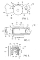
- a two-step roller finger follower assembly 100 comprises a follower body 102 having a central aperture 104 for receiving a high-lift follower 106 that is pivotably secured to body 102 via a pin 108.
- a coil torsion bias spring 110 is also disposed on pin 108 and is grounded at a first tang on body 102 and at a second tang on high-lift follower 106 such that follower 106 is urged rotationally within central aperture 104 and about pin 108 in a direction 112.
- First and second rollers 114 are mounted on an axle 116 that is mounted, preferably on needle bearings (not shown), in a bore through the sidewalls of body 102.
- Axle 116 passes through an arcuate slot 118 in high-lift follower 106, permitting the follower to rotate freely about pin 108 as just described.
- a first end 120 of body 102 includes a hemispherical socket (not visible) for pivotably receiving the spherical head of a hydraulic lash adjuster (not shown) upon which follower assembly 100 is mounted in an engine 122.
- a second end 124 of body 102 includes a pallet surface 126 for engaging and actuating the stem of an engine valve (not shown).
- Body 102 is further provided with a bore 128 for receiving a latching pin mechanism (not shown) for latching and unlatching high-lift follower 106 from body 102 in known fashion which need not be elaborated upon here.
- high lift follower 106 is provided with a relief 130 along one or both sides thereof, creating a land 132 that preferably is sloped with respect to the direction of travel of follower 106.
- a limiting stop 134 comprising a screw is threadedly received in a threaded bore in body 102 and extends into central aperture 104 and relief 130 so as to engage land 132 at a predetermined limit of rotational travel of follower 106 in direction 112 with respect to body 102.
- limiting stop screw 134 is tapered at the inner end thereof 135 to permit adjustment of the engagement point with land 132 and thus adjustment of the limit of rotational travel of follower 106.
- a lock nut 136 may be provided to secure screw 134 in a set position as desired.
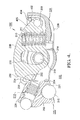
- a second two-step roller finger follower assembly 200 illustrates additional embodiments of a limiting stop in accordance with the invention. Two of the embodiments are shown together in assembly 200 for illustrative purposes but are intended to be used in the alternative.
- Assembly 200 is mechanically essentially identical with assembly 100 except that a compression spring 210 in a well 211 formed in high-lift follower 206 replaces torsion spring 110 in embodiment 100. Also note that a latching mechanism 213 of a similar type that would be used in assembly 100, and HLA head 215 are shown.
- Assembly 200 comprises a follower body 202 having a central aperture 204 for receiving a high-lift follower 206 that is pivotably secured to body 202 via a pin 208.
- a roller 214 is mounted on an axle 216 that is mounted, preferably on needle bearings (not shown), in a bore through the sidewalls of body 202.
- Axle 216 passes through an arcuate slot 218 in high-lift follower 206, permitting the follower to rotate freely about pin 208.
- a first end 220 of body 202 includes a hemispherical socket 221 for pivotably receiving the spherical head 215 of a hydraulic lash adjuster upon which follower assembly 200 is mounted in an engine 222.
- a second end 224 of body 202 includes a pallet surface 226 for engaging and actuating the stem of an engine valve (not shown).
- Body 202 is further provided with a bore 228 for receiving a latching pin mechanism 213 for latching and unlatching high-lift follower 206 from body 202 in known fashion.
- high lift follower 206 is provided with a relief 230 along the latching end thereof, creating a land 232.
- a limiting stop 234 comprising a roll pin is received in a boss 235 formed in body 202 and extends into relief 230 so as to engage land 232 at a predetermined limit of rotational travel of follower 206 with respect to body 202.
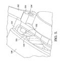
- a third embodiment is similar to the just-described second embodiment except that relief 330 and land 332 are formed along the side 333 of follower 306. Boss 335 is placed accordingly such that limiting stop 334, such as a roll pin, extends into relief 330 and engages land 332, thereby limiting the rotation of follower 306 within body 302.
- limiting stop 334 such as a roll pin
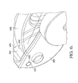
- a fourth embodiment is operative at the opposite end 405 of follower 406 from the previously-described embodiments.
- a limiting stop 434 such as a roll pin, is disposed in bores 435 in body 402 at an appropriate location such that motion of follower 406 is arrested by a contact point 432 with limiting stop 434 at an extreme of such motion.
- body 402 may be formed (not shown) in the functional shape of limiting stop 434 and may thereby provide an integral limiting stop at this location.
Landscapes
- Engineering & Computer Science (AREA)
- Mechanical Engineering (AREA)
- General Engineering & Computer Science (AREA)
- Valve-Gear Or Valve Arrangements (AREA)
Applications Claiming Priority (1)
| Application Number | Priority Date | Filing Date | Title |
|---|---|---|---|
| US11/820,789 US7798113B2 (en) | 2007-06-20 | 2007-06-20 | Two-step roller finger cam follower assembly having a follower travel limiter |
Publications (1)
| Publication Number | Publication Date |
|---|---|
| EP2006498A1 true EP2006498A1 (fr) | 2008-12-24 |
Family
ID=39719050
Family Applications (1)
| Application Number | Title | Priority Date | Filing Date |
|---|---|---|---|
| EP08157173A Withdrawn EP2006498A1 (fr) | 2007-06-20 | 2008-05-29 | Suiveur de came de contact à rouleau à deux étapes ayant un limiteur de trajectoire de suiveur |
Country Status (2)
| Country | Link |
|---|---|
| US (1) | US7798113B2 (fr) |
| EP (1) | EP2006498A1 (fr) |
Cited By (1)
| Publication number | Priority date | Publication date | Assignee | Title |
|---|---|---|---|---|
| EP3029283A1 (fr) * | 2014-12-04 | 2016-06-08 | Hyundai Motor Company | Appareil à levée variable de soupape |
Families Citing this family (17)
| Publication number | Priority date | Publication date | Assignee | Title |
|---|---|---|---|---|
| US7934477B2 (en) * | 2008-08-25 | 2011-05-03 | GM Global Technology Operations LLC | Rocker arm assembly |
| USD791190S1 (en) | 2015-07-13 | 2017-07-04 | Eaton Corporation | Rocker arm assembly |
| USD833482S1 (en) | 2015-07-13 | 2018-11-13 | Eaton Corporation | Rocker arm |
| CN108138608A (zh) | 2015-08-05 | 2018-06-08 | 伊顿智能动力有限公司 | 用于内部废气再循环的切换摇臂 |
| USD830414S1 (en) | 2015-12-10 | 2018-10-09 | Eaton S.R.L. | Roller rocker arm of an engine |
| CN109952415B (zh) | 2016-10-07 | 2022-03-11 | 伊顿智能动力有限公司 | 具有抽气止动件的三辊摇臂 |
| JP6736484B2 (ja) * | 2017-01-10 | 2020-08-05 | 株式会社オティックス | 内燃機関の可変動弁機構 |
| US10253657B2 (en) | 2017-02-20 | 2019-04-09 | Delphi Technologies Ip Limited | Switchable rocker arm with a travel stop |
| US10465566B2 (en) | 2017-08-30 | 2019-11-05 | Delphi Technologies Ip Limited | Switchable rocker arm with a travel stop |
| WO2019161976A1 (fr) | 2018-02-23 | 2019-08-29 | Eaton Intelligent Power Limited | Linguet à galet de commutation ayant une position de départ pouvant être rétablie |
| US10605126B2 (en) | 2018-04-17 | 2020-03-31 | Delphi Technologies Ip Limited | Switchable rocker arm |
| JP2020029817A (ja) * | 2018-08-22 | 2020-02-27 | 株式会社日進製作所 | 動弁装置 |
| US10519817B1 (en) * | 2018-08-29 | 2019-12-31 | Delphi Technologies Ip Limited | Switchable rocker arm with lash adjustment and travel stop |
| US10677106B2 (en) * | 2018-09-05 | 2020-06-09 | Delphi Technologies Ip Limited | Rocker arm |
| US10704429B2 (en) | 2018-09-27 | 2020-07-07 | Delphi Technologies Ip Limited | Switchable rocker arm |
| US10900385B2 (en) | 2019-01-29 | 2021-01-26 | Delphi Technologies Ip Limited | Switchable rocker arm |
| US10871087B2 (en) * | 2019-01-29 | 2020-12-22 | Delphi Technologies Ip Limited | Switchable rocker arm |
Citations (6)
| Publication number | Priority date | Publication date | Assignee | Title |
|---|---|---|---|---|
| US6532920B1 (en) * | 2002-02-08 | 2003-03-18 | Ford Global Technologies, Inc. | Multipositional lift rocker arm assembly |
| EP1338760A2 (fr) * | 2002-02-26 | 2003-08-27 | Delphi Technologies, Inc. | Culbuteur à galet à 2 positions dont le galet correspondant à la gamme de levée inférieure est en forme de bobine |
| US20040035381A1 (en) * | 2002-08-22 | 2004-02-26 | Ford Global Technologies, Inc. | Integrated solenoid board and cam ladder |
| US6925978B1 (en) * | 2004-08-24 | 2005-08-09 | Delphi Technologies, Inc. | Two-step roller finger cam follower having angled lock pin |
| EP1724447A1 (fr) * | 2005-05-09 | 2006-11-22 | Delphi Technologies, Inc. | Poussoir de commande a galet a deux etages |
| DE102005037053A1 (de) * | 2005-08-05 | 2007-02-08 | Schaeffler Kg | Schaltbarer Schlepphebel eines Ventiltriebs einer Brennkraftmaschine |
Family Cites Families (2)
| Publication number | Priority date | Publication date | Assignee | Title |
|---|---|---|---|---|
| US6769387B2 (en) * | 2002-10-19 | 2004-08-03 | General Motors Corporation | Compact two-step rocker arm assembly |
| US6966291B1 (en) * | 2004-10-28 | 2005-11-22 | Delphi Technologies, Inc. | Latch timing mechanism for a two-step roller finger cam follower |
-
2007
- 2007-06-20 US US11/820,789 patent/US7798113B2/en active Active
-
2008
- 2008-05-29 EP EP08157173A patent/EP2006498A1/fr not_active Withdrawn
Patent Citations (6)
| Publication number | Priority date | Publication date | Assignee | Title |
|---|---|---|---|---|
| US6532920B1 (en) * | 2002-02-08 | 2003-03-18 | Ford Global Technologies, Inc. | Multipositional lift rocker arm assembly |
| EP1338760A2 (fr) * | 2002-02-26 | 2003-08-27 | Delphi Technologies, Inc. | Culbuteur à galet à 2 positions dont le galet correspondant à la gamme de levée inférieure est en forme de bobine |
| US20040035381A1 (en) * | 2002-08-22 | 2004-02-26 | Ford Global Technologies, Inc. | Integrated solenoid board and cam ladder |
| US6925978B1 (en) * | 2004-08-24 | 2005-08-09 | Delphi Technologies, Inc. | Two-step roller finger cam follower having angled lock pin |
| EP1724447A1 (fr) * | 2005-05-09 | 2006-11-22 | Delphi Technologies, Inc. | Poussoir de commande a galet a deux etages |
| DE102005037053A1 (de) * | 2005-08-05 | 2007-02-08 | Schaeffler Kg | Schaltbarer Schlepphebel eines Ventiltriebs einer Brennkraftmaschine |
Cited By (2)
| Publication number | Priority date | Publication date | Assignee | Title |
|---|---|---|---|---|
| EP3029283A1 (fr) * | 2014-12-04 | 2016-06-08 | Hyundai Motor Company | Appareil à levée variable de soupape |
| US9587531B2 (en) | 2014-12-04 | 2017-03-07 | Hyundai Motor Company | Variable valve lift apparatus |
Also Published As
| Publication number | Publication date |
|---|---|
| US20080314340A1 (en) | 2008-12-25 |
| US7798113B2 (en) | 2010-09-21 |
Similar Documents
| Publication | Publication Date | Title |
|---|---|---|
| US7798113B2 (en) | Two-step roller finger cam follower assembly having a follower travel limiter | |
| US6668779B2 (en) | Two-step finger follower rocker arm assembly | |
| US6966291B1 (en) | Latch timing mechanism for a two-step roller finger cam follower | |
| US6925978B1 (en) | Two-step roller finger cam follower having angled lock pin | |
| US6691657B2 (en) | Two-step finger follower rocker arm | |
| US20080283003A1 (en) | Two-step roller finger cam follower | |
| US7849828B2 (en) | Rocker arm assembly | |
| US6615782B1 (en) | Two-step finger follower rocker arm | |
| US20030200947A1 (en) | Lock-pin cartridge for a two-step finger follower rocker arm | |
| JP4420493B2 (ja) | 圧縮エンジンブレーキ装置 | |
| US8047168B2 (en) | Continuously variable valve lift system for engine | |
| US7404386B1 (en) | Multi-step valve actuation system | |
| JP7526892B2 (ja) | ロストモーションエンジンバルブ作動システム内のロッカー制御 | |
| US20070113813A1 (en) | Two-step rocker arm having roller element cam followers | |
| EP2317084A1 (fr) | Système de culbuteur commutable | |
| US20040020454A1 (en) | Frameless variable valve actuation mechanism | |
| US20250389211A1 (en) | Valve actuation system comprising a discrete lost motion device | |
| US6487997B2 (en) | Springless poppet valve system | |
| US9920659B2 (en) | Coupling pin anti-rotation for a switchable roller finger follower | |
| US9903233B2 (en) | Coupling pin anti-rotation for a switchable roller finger follower | |
| CN115989359A (zh) | 具有切换设备的阀门操纵设备 | |
| CN114846223B (zh) | 闩锁组件和紧凑型摇臂组件 | |
| EP3628832A1 (fr) | Bras oscillant commutable | |
| US8794204B2 (en) | Valvetrain for overhead valve engine | |
| CN114320516A (zh) | 用于选择性停用发动机气门的具有带滚轮锁的摇臂组件的发动机气门系统 |
Legal Events
| Date | Code | Title | Description |
|---|---|---|---|
| PUAI | Public reference made under article 153(3) epc to a published international application that has entered the european phase |
Free format text: ORIGINAL CODE: 0009012 |
|
| AK | Designated contracting states |
Kind code of ref document: A1 Designated state(s): AT BE BG CH CY CZ DE DK EE ES FI FR GB GR HR HU IE IS IT LI LT LU LV MC MT NL NO PL PT RO SE SI SK TR |
|
| AX | Request for extension of the european patent |
Extension state: AL BA MK RS |
|
| AKX | Designation fees paid | ||
| REG | Reference to a national code |
Ref country code: DE Ref legal event code: 8566 |
|
| STAA | Information on the status of an ep patent application or granted ep patent |
Free format text: STATUS: THE APPLICATION IS DEEMED TO BE WITHDRAWN |
|
| 18D | Application deemed to be withdrawn |
Effective date: 20090625 |