EP2006559A2 - Système d'amortisseur pour palier magnétique avec supraconducteur haute température - Google Patents
Système d'amortisseur pour palier magnétique avec supraconducteur haute température Download PDFInfo
- Publication number
- EP2006559A2 EP2006559A2 EP08158429A EP08158429A EP2006559A2 EP 2006559 A2 EP2006559 A2 EP 2006559A2 EP 08158429 A EP08158429 A EP 08158429A EP 08158429 A EP08158429 A EP 08158429A EP 2006559 A2 EP2006559 A2 EP 2006559A2
- Authority
- EP
- European Patent Office
- Prior art keywords
- damper
- electrically conductive
- temperature superconductor
- conductive layer
- bearing
- Prior art date
- Legal status (The legal status is an assumption and is not a legal conclusion. Google has not performed a legal analysis and makes no representation as to the accuracy of the status listed.)
- Withdrawn
Links
- 239000002887 superconductor Substances 0.000 title claims abstract description 43
- 230000005291 magnetic effect Effects 0.000 title claims abstract description 38
- 230000005284 excitation Effects 0.000 claims abstract description 31
- 230000005520 electrodynamics Effects 0.000 claims abstract description 26
- 238000006243 chemical reaction Methods 0.000 claims abstract description 4
- 230000002787 reinforcement Effects 0.000 claims description 20
- 238000004804 winding Methods 0.000 claims description 14
- 230000004907 flux Effects 0.000 claims description 9
- 239000004020 conductor Substances 0.000 claims description 5
- 230000005294 ferromagnetic effect Effects 0.000 claims description 5
- XEEYBQQBJWHFJM-UHFFFAOYSA-N Iron Chemical compound [Fe] XEEYBQQBJWHFJM-UHFFFAOYSA-N 0.000 description 12
- 238000013016 damping Methods 0.000 description 11
- 229910052742 iron Inorganic materials 0.000 description 6
- 239000010949 copper Substances 0.000 description 5
- 238000010586 diagram Methods 0.000 description 5
- 230000000694 effects Effects 0.000 description 5
- 230000004913 activation Effects 0.000 description 4
- 238000001816 cooling Methods 0.000 description 4
- 229910052802 copper Inorganic materials 0.000 description 4
- 239000000463 material Substances 0.000 description 4
- 244000052769 pathogen Species 0.000 description 4
- 230000001717 pathogenic effect Effects 0.000 description 4
- RYGMFSIKBFXOCR-UHFFFAOYSA-N Copper Chemical compound [Cu] RYGMFSIKBFXOCR-UHFFFAOYSA-N 0.000 description 3
- 238000005452 bending Methods 0.000 description 3
- 230000008859 change Effects 0.000 description 3
- 238000010276 construction Methods 0.000 description 3
- 230000005415 magnetization Effects 0.000 description 3
- 229920000049 Carbon (fiber) Polymers 0.000 description 2
- 229910052782 aluminium Inorganic materials 0.000 description 2
- XAGFODPZIPBFFR-UHFFFAOYSA-N aluminium Chemical compound [Al] XAGFODPZIPBFFR-UHFFFAOYSA-N 0.000 description 2
- 239000004917 carbon fiber Substances 0.000 description 2
- 238000004146 energy storage Methods 0.000 description 2
- VNWKTOKETHGBQD-UHFFFAOYSA-N methane Chemical compound C VNWKTOKETHGBQD-UHFFFAOYSA-N 0.000 description 2
- 230000010355 oscillation Effects 0.000 description 2
- 230000000149 penetrating effect Effects 0.000 description 2
- 230000000712 assembly Effects 0.000 description 1
- 238000000429 assembly Methods 0.000 description 1
- 230000008901 benefit Effects 0.000 description 1
- 230000008094 contradictory effect Effects 0.000 description 1
- 238000006073 displacement reaction Methods 0.000 description 1
- 238000007667 floating Methods 0.000 description 1
- 239000012530 fluid Substances 0.000 description 1
- 230000003993 interaction Effects 0.000 description 1
- 238000005339 levitation Methods 0.000 description 1
- 238000012423 maintenance Methods 0.000 description 1
- 229910052751 metal Inorganic materials 0.000 description 1
- 239000002184 metal Substances 0.000 description 1
- 150000002739 metals Chemical class 0.000 description 1
- 238000005457 optimization Methods 0.000 description 1
- 230000009467 reduction Effects 0.000 description 1
- 230000003014 reinforcing effect Effects 0.000 description 1
- 230000003068 static effect Effects 0.000 description 1
- 230000001629 suppression Effects 0.000 description 1
- 230000031068 symbiosis, encompassing mutualism through parasitism Effects 0.000 description 1
Images


Classifications
-
- F—MECHANICAL ENGINEERING; LIGHTING; HEATING; WEAPONS; BLASTING
- F16—ENGINEERING ELEMENTS AND UNITS; GENERAL MEASURES FOR PRODUCING AND MAINTAINING EFFECTIVE FUNCTIONING OF MACHINES OR INSTALLATIONS; THERMAL INSULATION IN GENERAL
- F16C—SHAFTS; FLEXIBLE SHAFTS; ELEMENTS OR CRANKSHAFT MECHANISMS; ROTARY BODIES OTHER THAN GEARING ELEMENTS; BEARINGS
- F16C32/00—Bearings not otherwise provided for
- F16C32/04—Bearings not otherwise provided for using magnetic or electric supporting means
- F16C32/0406—Magnetic bearings
- F16C32/0408—Passive magnetic bearings
- F16C32/0436—Passive magnetic bearings with a conductor on one part movable with respect to a magnetic field, e.g. a body of copper on one part and a permanent magnet on the other part
- F16C32/0438—Passive magnetic bearings with a conductor on one part movable with respect to a magnetic field, e.g. a body of copper on one part and a permanent magnet on the other part with a superconducting body, e.g. a body made of high temperature superconducting material such as YBaCuO
-
- F—MECHANICAL ENGINEERING; LIGHTING; HEATING; WEAPONS; BLASTING
- F16—ENGINEERING ELEMENTS AND UNITS; GENERAL MEASURES FOR PRODUCING AND MAINTAINING EFFECTIVE FUNCTIONING OF MACHINES OR INSTALLATIONS; THERMAL INSULATION IN GENERAL
- F16C—SHAFTS; FLEXIBLE SHAFTS; ELEMENTS OR CRANKSHAFT MECHANISMS; ROTARY BODIES OTHER THAN GEARING ELEMENTS; BEARINGS
- F16C27/00—Elastic or yielding bearings or bearing supports, for exclusively rotary movement
-
- F—MECHANICAL ENGINEERING; LIGHTING; HEATING; WEAPONS; BLASTING
- F16—ENGINEERING ELEMENTS AND UNITS; GENERAL MEASURES FOR PRODUCING AND MAINTAINING EFFECTIVE FUNCTIONING OF MACHINES OR INSTALLATIONS; THERMAL INSULATION IN GENERAL
- F16C—SHAFTS; FLEXIBLE SHAFTS; ELEMENTS OR CRANKSHAFT MECHANISMS; ROTARY BODIES OTHER THAN GEARING ELEMENTS; BEARINGS
- F16C29/00—Bearings for parts moving only linearly
-
- F—MECHANICAL ENGINEERING; LIGHTING; HEATING; WEAPONS; BLASTING
- F16—ENGINEERING ELEMENTS AND UNITS; GENERAL MEASURES FOR PRODUCING AND MAINTAINING EFFECTIVE FUNCTIONING OF MACHINES OR INSTALLATIONS; THERMAL INSULATION IN GENERAL
- F16F—SPRINGS; SHOCK-ABSORBERS; MEANS FOR DAMPING VIBRATION
- F16F15/00—Suppression of vibrations in systems; Means or arrangements for avoiding or reducing out-of-balance forces, e.g. due to motion
- F16F15/02—Suppression of vibrations of non-rotating, e.g. reciprocating systems; Suppression of vibrations of rotating systems by use of members not moving with the rotating systems
- F16F15/03—Suppression of vibrations of non-rotating, e.g. reciprocating systems; Suppression of vibrations of rotating systems by use of members not moving with the rotating systems using magnetic or electromagnetic means
-
- F—MECHANICAL ENGINEERING; LIGHTING; HEATING; WEAPONS; BLASTING
- F16—ENGINEERING ELEMENTS AND UNITS; GENERAL MEASURES FOR PRODUCING AND MAINTAINING EFFECTIVE FUNCTIONING OF MACHINES OR INSTALLATIONS; THERMAL INSULATION IN GENERAL
- F16C—SHAFTS; FLEXIBLE SHAFTS; ELEMENTS OR CRANKSHAFT MECHANISMS; ROTARY BODIES OTHER THAN GEARING ELEMENTS; BEARINGS
- F16C29/00—Bearings for parts moving only linearly
- F16C29/002—Elastic or yielding linear bearings or bearing supports
Definitions
- the present invention relates to a damper system suitable for high temperature superconductor bearings, and more particularly to high temperature superconductor bearings equipped with the damper system.
- a high-temperature superconductor bearing comprises a permanent magnet arrangement as excitation system and a high-temperature superconductor, wherein the high-temperature superconductor is penetrated by the magnetic flux of the permanent magnet assembly.
- Tc critical temperature
- HTS bearings can be used for non-contact storage of rotating systems. These bearings consist in principle of a fixed part, the stator, and a rotating part, the rotor.
- the stator contains the high-temperature superconductor and the rotor is provided with a permanent magnet arrangement which acts as an excitation system.
- the high-temperature superconductor is located in a Dewar for cooling.
- An example of this is the European patent application EP 1 767 798 A1 as well as on WO 02/06688 A1 to which full content is referred, in particular for the structure and operation of HTSL bearings.
- HTS bearings are characterized by a self-stable, non-contact operation and thus offer a very smooth running and low maintenance. Furthermore, they are characterized by a great insensitivity to larger ones Due to their functional principle, they enable safe operation for hours even after the failure of all external energy suppliers.
- damper for example, squeeze film damper to integrate into the storage system.
- this proven measure for vibration suppression can not be used in contactless superconducting magnetic bearings, since vibration analyzes with magnetic bearing data show that their rigidity is too low and the stator part of the magnetic bearing has too large a mass. This is where the present invention begins.
- an electrodynamically acting damper which has a permanent-magnet exciter system and an electrically conductive layer, wherein the exciter system generates a gradient field which interacts with the electrically conductive layer.
- the exciter system may be a permanent magnet or solenoid assembly.
- the exciter system preferably has a large field gradient in the direction of attenuation.
- the electrically conductive layer is preferably made of a material of high electrical conductivity, such as copper or aluminum.
- the shape of the electrically conductive layer depends on the geometric specifications of the arrangement, such as the bearing, in which the damper is installed. It can be planar or curved, it can be configured as a cylinder, circle, disk, plate, etc.
- the electrodynamically acting damper system according to the invention can in principle be used for applications requiring a corresponding vibration damping, as for conventional bearings including magnetic bearings.
- the electrodynamic damper of the present invention is also suitable for vibration damping in high temperature superconductor bearings. These can be designed, for example, linear, planar or cylindrical.
- FIG. 1 1 denotes the high-temperature superconductor and 2 the permanent magnet arrangement.
- the permanent magnet assembly consists of a plurality of individual permanent magnets, which are arranged side by side and in series.
- the permanent magnet arrangement as an excitation system influences the number of degrees of freedom of movement and the rigidity of the bearing via the spatial gradient of the exciter field.
- FIG. 1 shown linear HTSL bearings allowed in a pathogen system according to FIG. 2a , which consists of magnets magnetized in the longitudinal direction, in this direction a force-free movement.
- FIG. 2b shows alternately magnetized, so the direction of movement of the floating body is limited in all six degrees of freedom.
- the deflection depends on the spring stiffnesses.
- the magnetization direction of the permanent magnets is arranged by arrows.
- FIGS. 3a to 3c show the conversion of a linear superconducting bearing assembly ( FIG. 3a ) into a planar ( FIG. 3b ) and in a cylindrical embodiment ( Figure 3c ) by bending the linear bearing assembly about the respective axes.
- the permanent magnets 2 are arranged between ferromagnetic flux guide pieces 3, for example iron poles.
- the magnetization of the permanent magnets is indicated by arrows.
- the planar embodiment according to FIG. 3b is created by bending the linear bearing assembly about the axis vertical to the sheet plane.
- FIG. 3b In addition to the excitation system 2, 3 and the high-temperature superconductor 1 further elements of a high-temperature superconductor bearing are indicated as the cold head 4 for dissipating the heat from the superconductor material and a thermally insulating support device 5.
- Such planar bearings can in particular for rotating energy storage, such as a Carbon fiber cylinder 6, are used.
- Figure 3c shows a cylindrical embodiment formed by bending the linear array according to FIG. 3a around an axis parallel to the sheet plane is obtained.
- Such cylindrical bearings are used in particular for rotating shafts.
- FIG. 4 schematically shows the structure of a planar bearing with the rotor 7.
- the Rothn is in FIG. 4 schematically shows the activation position and the working position.
- the activation position corresponds to the position of the rotor to the HTSL during the cooling of the high-temperature superconductor and the operating position of the deflection during operation, which is required for the generation of force.
- Also indicated by an arrow is the external load due to the rotor weight, which must be compensated by the magnetic bearing after the cooling phase.
- FIG. 5 shows schematically the structure of a cylindrical bearing for horizontally oriented rotors.
- a linear electrodynamic damper system according to the present invention is disclosed in U.S. Pat FIG. 6a and comprises an electrically conductive layer 8 and a permanent magnet excitation system 9.
- the electrically conductive layer 8 can in principle be formed from any material with good electrical conductivity. Examples include metals such as copper or aluminum. Copper has proven to be particularly suitable. However, other materials with similar properties can readily be used.
- the excitation system 9 is formed according to the exciting system of the superconducting bearing of a number of permanent magnets 9a, which may be arranged between ferromagnetic flux guides 9b, for example iron poles.
- the magnetization of the permanent magnets 9a is again indicated by arrows.
- the damped directions of movement are indicated by the arrow cross.
- the permanent magnet excitation system generates a gradient field with which the electrically conductive layer 8 is brought into interaction and wherein upon displacement of the excitation system, for example by rotor vibrations a damping force is built up.
- the electrodynamic damper according to the invention thus enables a contact-free damping. In addition, unlike conventional dampers no fluid is required.
- FIG. 6b is the field distribution of the electrodynamic damper according to FIG. 6a shown.
- the pathogen system should preferably, as well as in FIG. 6b shown to have a large field gradient in the direction of attenuation.
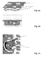
- FIG. 7a the construction of a cylindrical electrodynamic damper is shown.
- the electrically conductive layer 8 has a cylindrical shape.
- the field distribution in longitudinal section of in Figure 7a shown damper shows FIG. 7b ,
- the exciter system 9 for the damper is connected to the rotor 7 or the rotor shaft of the bearing. If now connected to the rotor excitation system 9 due to forces, as shown in Figure 7a indicated by arrows axially and / or radially moved within the cylinder formed from the electrically conductive layer 8, eddy currents are generated in the cylinder (Faraday's law, Maxwell's equation), which generate forces that are proportional to the speed. These forces are called damping forces in vibration theory and can significantly limit the vibration amplitudes, depending on their size.
- the excitation system 9 of the damper is usually connected to the movable part of the bearing, for example the rotor or the rotor shaft.
- An example of this shows FIG. 7b , According to FIG. 7b the excitation system for the damper 9 is connected to the rotor 7 and surrounds this circular.
- the electrically conductive layer 8 may be attached to the dewar wall in the warm bore of the dewar surrounding the high temperature superconductor.
- the damper system according to the invention can also be constructed from a sequence of excitation systems 9 and electrically conductive layer 8 arranged one behind the other.
- FIG. 8 a planar-cylindrical electrodynamic damper system disposed on a rotor shaft 7.
- the system consists here of several alternately successively arranged circular discs of electrically conductive material between each of which an excitation system 9 is arranged for the damper.
- the field distribution of the electrodynamic damper system according to FIG. 8a in working position of the warehouse is in FIG. 8b shown.
- the damper system as it is in FIG. 8 is shown, may be mounted downstream of the bearing on the rotor shaft.
- the electrodynamic damper may be mechanically integrated into the magnetic bearing itself, as in FIG. 9a and as an enlarged detail in FIG. 9b shown.
- the electrically conductive plate 8 and the excitation system 9 are located within the rotor 7, wherein reference numeral 10 is the outer wall of the rotor 7.
- the electrically conductive layer 8 is arranged here between the rotor wall 10 and the excitation system 9 of the damper.
- FIG. 9b shown partial section shows that the damper is integrated as an independent unit.
- the total length of the storage area consisting of magnetic bearing and damper can be drastically shortened. This not only has the advantage of saving space, but additionally increases the natural frequency of the rotor unit.
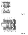
- FIG. 10 An advantageous embodiment of the embodiment according to FIG. 9 is in FIG. 10 shown.
- the excitation system 2, 3 of the magnetic bearing is used simultaneously as excitation system for the electrodynamic damper.
- the electrically conductive layer 8 is fixedly arranged between the excitation system 2, 3 and the outer surface of a support structure 13.
- a volume and mass reduction associated with this embodiment which advantageously increases the natural resonance of the system.
- the damping properties of the electrodynamic damper according to the invention depend strongly on the exciter system (amplitude and gradient of the field) and on the quality (conductivity and thickness) of the electrically conductive layer 8 as damper reaction part.
- the field density between the iron poles 9b is increased.
- An enhancement of the damping effect can therefore be achieved if the permanent magnets 9a are placed back between the iron poles 9b and the electrically conductive layer 8 is reinforced in this area by providing a reinforcement, for example strips. This reinforcement can protrude into the intermediate pole regions.
- a reinforcement for example strips. This reinforcement can protrude into the intermediate pole regions.
- FIG. 12 An embodiment of the embodiment according to FIG. 11 shows FIG. 12 ,
- the electrically conductive layer 8 is formed of individual strips disposed between the poles over the recessed permanent magnet.
- a base plate like in FIG. 11 on which the strips are applied is not required. So that the eddy currents induced due to the vibrations can close better, the strips can be connected to a winding. This can be done by a short circuit by webs at the front and rear ends of the strips, wherein a so-called damper winding is formed.
- FIG. 12 An embodiment of the damper winding according to FIG. 12 shows FIG. 13 ,
- the damper winding is realized in that the strips are alternately connected at the rear and front and additionally the two winding ends are short-circuited by a bridge.
- the damper assembly is only mechanically connected to the magnetic bearings to be damped.
- a more compact construction can be obtained if the electrodynamic damper arrangement is arranged directly in the effective region of the superconducting magnetic bearing.
- the electrically conductive layer 8 is located between the exciter system 2, 3 of the bearing and the high-temperature superconductor 1.
- the damper is an integral part of the magnetic bearing.
- the damping characteristic is intensified by amplifying the electrically conductive layer 8.
- the superconductor 1 after cooling (force activation), holds the magnetic field penetrating it and allows practically no field changes. But the effect of the damper is based precisely on such field changes. When designing is therefore an area to create in which the magnetic field can squeeze. Therefore, in the effective range of a superconducting magnetic bearing integrated dampers are also called Quetschfelddämpfer.
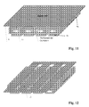
- Such Quetschfelddämpferan extract can be integrated into concentric-cylindrical and planar-cylindrical magnetic bearing assemblies, as for example in the FIGS. 15 and 16 are shown.
- the electrically conductive layer 8 in each case in the gap, or the columns, between high-temperature superconductor 1 and exciter system 2, 3 arranged.
- the electrically conductive layer 8 can be mounted on the outer wall of the Dewar surrounding the HTSC.
- the embodiments of the electrically conductive layer 8 according to FIGS. 11, 12 and 13 can be used, wherein the electrically conductive layer 8 has strip-shaped reinforcements or is a damper winding formed of strips. Examples of such embodiments are in FIGS. 14 to 17 shown.
- FIG. 14 a linear magnetic bearing with a strip-shaped reinforced electrically conductive layer 8, as in FIG. 11 is shown.
- the height and width of the strip-shaped reinforcements are in this case preferably designed so that, after the activation of the superconducting bearing and the expected maximum deflection from this position, for example due to dynamic loads, no contact between the strip-shaped reinforcements 11 and the exciter system 2, 3 is coming. By resetting the permanent magnets 2, an increased vertical oscillation can be allowed.
- FIG. 15 shows a concentric-cylindrical magnetic bearing with Quetschfelddämpfer and equipped with strip-shaped reinforcements electrically conductive plate 8 according to FIG. 11 .
- the outer radius of the exciter system r pol is smaller (for example, approximately 0.1 mm) than that of the overall system Inner radius of the annular reinforcements r Cu-i must be selected.
- the maximum height of the annular reinforcements (r Cu, a -r Cu, i ) is determined by the maximum radial deflection of the bearing, which is (r pol -r pM ).
- the permanent magnets between the poles can be placed slightly set back, for example, about 1 to 2 mm.
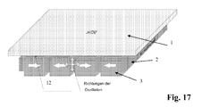
- FIG. 16 shows a planar-cylindrical magnetic bearing with integrated Quetschfelddämpfer and strip-shaped reinforced electrically conductive layer. 8
- This embodiment is not subject to the restrictions on the height of the reinforcing strips 11 as in the concentric cylindrical magnetic bearing according to FIG. 16 , As in the embodiment according to FIG. 17 the individual modules are pushed one after the other onto the rotor shaft, the strip-shaped reinforcements 11 can also protrude into the exciter system 2, 3 into the depressions formed by the withdrawn permanent magnets.
- the width of the strip-shaped reinforcements in this magnetic bearing design depends on the maximum radial deflection of the exciter system 2, 3 during operation.
- the base plate on which the strip-shaped reinforcements 11 are applied should be as thin as possible, so that the distance between the high-temperature superconductor 1 and excitation system 2, 3 remains low and the carrying properties of the magnetic bearing are not affected as possible. This also applies to the embodiments shown above according to the Figures 14 and 15 ,
- a damper winding (with or without webs) can be used, as in the Figures 12 and 13 is shown.
- FIG. 17 shown by way of example for a linear magnetic bearing.
Landscapes
- Engineering & Computer Science (AREA)
- General Engineering & Computer Science (AREA)
- Mechanical Engineering (AREA)
- Physics & Mathematics (AREA)
- Electromagnetism (AREA)
- Acoustics & Sound (AREA)
- Aviation & Aerospace Engineering (AREA)
- Magnetic Bearings And Hydrostatic Bearings (AREA)
Applications Claiming Priority (1)
| Application Number | Priority Date | Filing Date | Title |
|---|---|---|---|
| DE102007028018A DE102007028018A1 (de) | 2007-06-19 | 2007-06-19 | Dämpfersystem für Hochtemperatur-Supraleiterlager |
Publications (2)
| Publication Number | Publication Date |
|---|---|
| EP2006559A2 true EP2006559A2 (fr) | 2008-12-24 |
| EP2006559A3 EP2006559A3 (fr) | 2011-02-09 |
Family
ID=39777008
Family Applications (1)
| Application Number | Title | Priority Date | Filing Date |
|---|---|---|---|
| EP08158429A Withdrawn EP2006559A3 (fr) | 2007-06-19 | 2008-06-17 | Système d'amortisseur pour palier magnétique avec supraconducteur haute température |
Country Status (2)
| Country | Link |
|---|---|
| EP (1) | EP2006559A3 (fr) |
| DE (1) | DE102007028018A1 (fr) |
Cited By (5)
| Publication number | Priority date | Publication date | Assignee | Title |
|---|---|---|---|---|
| DE102008048210A1 (de) * | 2008-09-20 | 2010-05-12 | Oerlikon Leybold Vacuum Gmbh | Dämpfungsvorrichtung |
| WO2010094263A3 (fr) * | 2009-02-17 | 2011-03-03 | Schaeffler Technologies Gmbh & Co. Kg | Palier supraconducteur et son procédé de montage |
| WO2019037836A1 (fr) * | 2017-08-22 | 2019-02-28 | Evico Gmbh | Palier magnétique supraconducteur ayant une une couche électro-conductrice en tant qu'amortisseur à courant de foucault |
| US20230170827A1 (en) * | 2021-11-30 | 2023-06-01 | The Florida State University Research Foundation, Inc. | Magnetic levitation based low-gravity system |
| CN119508405A (zh) * | 2024-11-18 | 2025-02-25 | 西北工业大学 | 一种高温超导钉扎悬浮主被动混合隔振系统及方法 |
Families Citing this family (1)
| Publication number | Priority date | Publication date | Assignee | Title |
|---|---|---|---|---|
| CN102454701A (zh) * | 2010-10-21 | 2012-05-16 | 吴小平 | (多极化取向)互厄及层叠式永磁悬浮轴承 |
Citations (2)
| Publication number | Priority date | Publication date | Assignee | Title |
|---|---|---|---|---|
| WO2002006688A1 (fr) | 2000-07-18 | 2002-01-24 | Atlas Copco Energas Gmbh | Montage sur palier magnetique |
| EP1767798A1 (fr) | 2005-09-23 | 2007-03-28 | Nexans | palier magnétique supraconductive |
Family Cites Families (12)
| Publication number | Priority date | Publication date | Assignee | Title |
|---|---|---|---|---|
| US3929390A (en) * | 1971-12-22 | 1975-12-30 | Cambridge Thermionic Corp | Damper system for suspension systems |
| JPS5226578B2 (fr) * | 1974-02-08 | 1977-07-14 | ||
| JPS5751038A (en) * | 1980-09-07 | 1982-03-25 | Ricoh Co Ltd | Damping device for movable body performing rectilinear motion |
| JPS60129423A (ja) * | 1983-12-19 | 1985-07-10 | Hitachi Ltd | 磁気軸受 |
| US5319275A (en) * | 1990-09-17 | 1994-06-07 | Maglev Technology, Inc. | Magnetic levitation self-regulating systems having enhanced stabilization forces |
| JPH0751971B2 (ja) * | 1991-03-29 | 1995-06-05 | 株式会社四国総合研究所 | 軸受装置 |
| US5196748A (en) * | 1991-09-03 | 1993-03-23 | Allied-Signal Inc. | Laminated magnetic structure for superconducting bearings |
| JPH0681845A (ja) * | 1992-09-03 | 1994-03-22 | Koyo Seiko Co Ltd | 超電導軸受装置 |
| JPH06173948A (ja) * | 1992-12-11 | 1994-06-21 | Hitachi Ltd | 磁気軸受の磁気ダンパ装置及び磁気軸受装置 |
| JP3677088B2 (ja) * | 1994-10-19 | 2005-07-27 | 新日本製鐵株式会社 | 超電導磁気軸受 |
| DE10120623B4 (de) * | 2000-07-13 | 2009-11-19 | Adelwitz Technologiezentrum Gmbh (Atz) | Zentrifuge mit einem zur Aufnahme von Zentrifugiergut vorgesehenen Rotor |
| DE10358341B4 (de) * | 2003-12-12 | 2010-03-25 | Siemens Ag | Vorrichtung zum Lagern einer Kühlmittelzuführung für supraleitende Maschinen |
-
2007
- 2007-06-19 DE DE102007028018A patent/DE102007028018A1/de not_active Withdrawn
-
2008
- 2008-06-17 EP EP08158429A patent/EP2006559A3/fr not_active Withdrawn
Patent Citations (2)
| Publication number | Priority date | Publication date | Assignee | Title |
|---|---|---|---|---|
| WO2002006688A1 (fr) | 2000-07-18 | 2002-01-24 | Atlas Copco Energas Gmbh | Montage sur palier magnetique |
| EP1767798A1 (fr) | 2005-09-23 | 2007-03-28 | Nexans | palier magnétique supraconductive |
Cited By (6)
| Publication number | Priority date | Publication date | Assignee | Title |
|---|---|---|---|---|
| DE102008048210A1 (de) * | 2008-09-20 | 2010-05-12 | Oerlikon Leybold Vacuum Gmbh | Dämpfungsvorrichtung |
| WO2010094263A3 (fr) * | 2009-02-17 | 2011-03-03 | Schaeffler Technologies Gmbh & Co. Kg | Palier supraconducteur et son procédé de montage |
| WO2019037836A1 (fr) * | 2017-08-22 | 2019-02-28 | Evico Gmbh | Palier magnétique supraconducteur ayant une une couche électro-conductrice en tant qu'amortisseur à courant de foucault |
| US20230170827A1 (en) * | 2021-11-30 | 2023-06-01 | The Florida State University Research Foundation, Inc. | Magnetic levitation based low-gravity system |
| US12512772B2 (en) * | 2021-11-30 | 2025-12-30 | The Florida State University Research Foundation, Inc. | Magnetic levitation based low-gravity system |
| CN119508405A (zh) * | 2024-11-18 | 2025-02-25 | 西北工业大学 | 一种高温超导钉扎悬浮主被动混合隔振系统及方法 |
Also Published As
| Publication number | Publication date |
|---|---|
| DE102007028018A1 (de) | 2008-12-24 |
| EP2006559A3 (fr) | 2011-02-09 |
Similar Documents
| Publication | Publication Date | Title |
|---|---|---|
| DE69126210T2 (de) | Supraleitende magnetlager für hohe temperaturen | |
| DE3844563C2 (fr) | ||
| EP2006559A2 (fr) | Système d'amortisseur pour palier magnétique avec supraconducteur haute température | |
| EP3818625B2 (fr) | Procédé pour déplacer un rotor dans un système d'entraînement planaire | |
| EP3356693B1 (fr) | Palier, en particulier pour un ensemble de sustentation magnétique | |
| DE69610008T2 (de) | Schwungrad Energiespeicherungssystem | |
| EP2304257B1 (fr) | Palier magnétique à éléments supraconducteurs à haute température | |
| DE2420814A1 (de) | Magnetisches lagerelement, insbesondere axiallagerung | |
| DE3409047A1 (de) | Magnetlager zur dreiachsigen lagerstabilisierung von koerpern | |
| DE10303307B4 (de) | Maschine mit einem Rotor und einer supraleltenden Rotorwicklung | |
| EP1313951A1 (fr) | Pompe a vide | |
| DE102005030139A1 (de) | Vorrichtung zur magnetischen Lagerung einer Rotorwelle mit Radialführung und Axialregelung | |
| DE1933031B2 (de) | Magnetische Lagerung | |
| DE102016108646B4 (de) | Elektrodynamische Bremse | |
| WO2000013297A1 (fr) | Actionneur electromagnetique dote d'un systeme ressort-masse oscillant | |
| EP1895315A2 (fr) | Arrangement magnétique de bobine séparée doté d'une construction mécanique améliorée | |
| DE4436831A1 (de) | Einrichtung zur magnetischen Lagerung einer Rotorwelle unter Verwendung von Hoch-T¶c¶-Supraleitermaterial | |
| DE102011089445A1 (de) | Verfahren zur Reduzierung von mechanischen Schwingungen in einem Magnetresonanzbildgebungssystem | |
| DE102013101671A1 (de) | Adaptiver Drehschwingungstilger mit einer über Blattfedern an einer Nabe elastisch gelagerten ringförmigen Tilgermasse | |
| EP3093965B1 (fr) | Moteur linéaire supercarré | |
| DE10238932B3 (de) | Als Sensor und/oder Aktuator einsetzbares Bauteil | |
| DE102007034045A1 (de) | Elektrodynamischer Erreger | |
| DE102005028209B4 (de) | Magnetische Lagereinrichtung einer Rotorwelle gegen einen Stator mit ineinander greifenden Rotorscheibenelementen und Statorscheibenelementen | |
| DE29621166U1 (de) | Wechselstrommaschine, insbesondere Transversalflußmaschine | |
| DE102018213731A1 (de) | Waagevorrichtung |
Legal Events
| Date | Code | Title | Description |
|---|---|---|---|
| PUAI | Public reference made under article 153(3) epc to a published international application that has entered the european phase |
Free format text: ORIGINAL CODE: 0009012 |
|
| 17P | Request for examination filed |
Effective date: 20080617 |
|
| AK | Designated contracting states |
Kind code of ref document: A2 Designated state(s): AT BE BG CH CY CZ DE DK EE ES FI FR GB GR HR HU IE IS IT LI LT LU LV MC MT NL NO PL PT RO SE SI SK TR |
|
| AX | Request for extension of the european patent |
Extension state: AL BA MK RS |
|
| RAP1 | Party data changed (applicant data changed or rights of an application transferred) |
Owner name: NEXANS |
|
| PUAL | Search report despatched |
Free format text: ORIGINAL CODE: 0009013 |
|
| AK | Designated contracting states |
Kind code of ref document: A3 Designated state(s): AT BE BG CH CY CZ DE DK EE ES FI FR GB GR HR HU IE IS IT LI LT LU LV MC MT NL NO PL PT RO SE SI SK TR |
|
| AX | Request for extension of the european patent |
Extension state: AL BA MK RS |
|
| AKX | Designation fees paid |
Designated state(s): AT BE BG CH CY CZ DE DK EE ES FI FR GB GR HR HU IE IS IT LI LT LU LV MC MT NL NO PL PT RO SE SI SK TR |
|
| STAA | Information on the status of an ep patent application or granted ep patent |
Free format text: STATUS: THE APPLICATION IS DEEMED TO BE WITHDRAWN |
|
| 18D | Application deemed to be withdrawn |
Effective date: 20150103 |